15.7 Ramps & Direct Connectors
15.7.1 Types of Ramps
The term "ramp" includes all types, arrangements, and sizes of turning roadways that connect two or more legs at an interchange. The components of a ramp are a terminal at each leg and a connecting road, usually with some curvature, and on a grade. Generally, the horizontal and vertical alignment standards of ramps are below that of the intersecting highway, but in some cases it may be equal.
The basic types of ramps are:
- Diagonal;
- One quadrant;
- Loop and semidirect;
- Outer connection; and
- Directional.
For further information on these basic ramp types, refer to Chapter 10 of
15.7.2 General Ramp Design Considerations
15.7.2.1 Design Speed
All ramps and connections should be designed to enable vehicles to leave and enter the traveled way of the freeway at 85 percent (desirable) to 70 percent (usual) of the freeway's design speed, rounded up to the nearest 5 mph increment, and limiting the speed differential to 10 mph on the upper range and 20 mph for the mid-range. The upper and mid-range design speeds are not always practical (e.g., constrained ROW or retrofit to existing frontage roads, etc.) and lower design speeds may be selected upon review from Design Division, but they should not be less than the lower range presented in
However, every effort should be made to meet the desirable ramp/connector design speed. These speeds do not pertain to ramp terminals, which should be properly transitioned and provided with speed-change facilities adequate for the highway speed involved.
Where the ramp joins a frontage road, the design speed over the length of the ramp may vary, with the portion of the ramp closer to the frontage road being designed to the frontage road speed (i.e., the lower speed).
The independent design speed of the ramp should normally be assumed to be from the end of one physical nose to the beginning of the opposite physical nose.
See
for the definition of gore area characteristics.The design speed for a ramp should not be less than the design speed on the intersecting frontage roads. Refer to
for additional guidance on the application of the ranges of ramp design speed shown in
. Refer also to
Guides for more detailed analysis.
Ramp/Connector Design Speed 2 (mph) | Highway Design Speed (mph) | ||||||||||
30 | 35 | 40 | 45 | 50 | 55 | 60 | 65 | 70 | 75 | 80 | |
Upper Range (85%) | 25 | 30 | 35 | 40 | 45 | 50 | 50 | 55 | 60 | 65 | 70 |
Mid- Range (70%) | 20 | 25 | 30 | 30 | 35 | 40 | 45 | 45 | 50 | 55 | 60 |
Lower Range (50%) | 15 | 20 | 20 | 25 | 25 | 30 | 30 | 35 | 35 | 40 | 40 |
Notes: | |||||||||||
1. For corresponding superelevation methodology see Table 4-3. 2. 2.Upper-range values of design speed generally are not attainable on loop ramps. For highway design speeds above 50 mph, loop design speed should be no less than 20 mph. | |||||||||||
15.7.3 Ramp Geometrics
15.7.3.1 Entrance Ramp Connections.
The horizontal geometry of entrance ramps will depend on the design speeds of the ramp, the connecting frontage road, and the connecting freeway. The departure from the frontage road should be a smooth transition appropriate for the design speed and speed classification (low speed/high speed) of the frontage road. The pavement elevation and cross slope of the departing ramp should match the pavement elevation and cross slope of the connecting frontage road up to the physical nose. Once the ramp is independent of the connecting frontage road, the ramp horizontal geometry and cross slope should be set to the design speed of the ramp. Where the ramp connects to the freeway, beyond the physical nose, the pavement elevation and cross slope of the entering ramp should match the pavement elevation and cross slope of the connecting freeway.
15.7.3.2 Exit Ramp Connections.
The horizontal geometry of the exit ramps will depend on the design speeds of the ramp, the connecting freeway, and the connecting frontage road. The departure from the freeway may be either tangent or parallel. The pavement elevation and cross slope of the departing ramp should match the pavement elevation and cross slope of the connecting freeway up to the physical nose. Once the ramp is independent of the connecting freeway, the ramp horizontal geometry and cross slope should be set to the design speed of the ramp. Where the ramp connects to the frontage road, beyond the physical nose, the pavement elevation and cross slope of the exiting ramp should match the pavement elevation and cross slope of the connecting frontage road.
15.7.3.3 Gores
The term “gore” indicates an area at the junction of entrance or exit ramps with the mainlane or frontage roads which is illustrated in
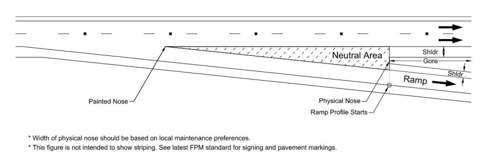
Figure 15-22: Typical Gore Area Characteristics
For an exit ramp junction at the mainlane, the physical nose is a point downstream from the painted nose of the gore, having some dimensional width that separates the roadways. The painted nose is a point, with no dimensional width, occurring where the travel ways intersect for the mainlane and ramp. The neutral area refers to the triangular area between the painted nose and physical nose.
The geometric layout of these is an important part of exit ramp terminal design. It is the decision point area that should be clearly seen and understood by approaching drivers and it should have a geometric shape appropriate for the likely speeds at that point. In a series of interchanges along a freeway, the gores should be uniform and have the same appearance to drivers.
The gore area, and the unpaved area beyond, should be kept as free of obstructions as practical to provide a clear recovery area. The unpaved area beyond the physical nose should be graded to be as nearly level with the roadways as practical so that vehicles inadvertently entering will not be overturned or abruptly stopped by steep slopes.
15.7.3.4 Grades and Profiles.
For design controls for crest and sag vertical curves on ramps and direct connectors, see
and
. Longer vertical curves with increased stopping sight distances should be provided wherever possible. See
for guidance on grade breaks without a vertical curve.
The tangent or controlling grade on ramps and direct connectors should be as flat as possible, and
preferably should be limited to 4 percent or less.
Maximum ramp grades are shown in
. In general, these grades should be used infrequently and only when necessary. Engineering judgement should be exercised when there are certain geometric constraints or topographic conditions that permit the use of these maximum grades.Ramp Design Speed (mph) | Max. Grade (%) |
25 to 30 | 7 |
35 to 40 | 6 |
Greater than or equal to 45 | 5 |
The ramp should have an independent profile from physical nose to physical nose. The profile grade within the neutral area should be designed as a projection of the connecting road profile and cross slope.
shows typical characteristics of ramp profile limits.
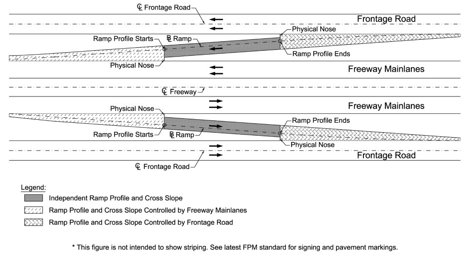
Figure 15-23: Typical Ramp Profile Characteristics
In some cases, it may be impractical to match the projected roadway profile and cross slope when designing the ramp proper profile. For these situations, a separated median area with mountable curb or barrier that warps the neutral area to join the projected profile of the connecting roadway and ramp proper may be considered. If a raised median is not preferred, surfaced mounted delineators may be used within the warped neutral area to discourage drivers from traversing this part of the ramp. See
for illustrations of a warped neutral area and
for maximum algebraic differences in cross slope.
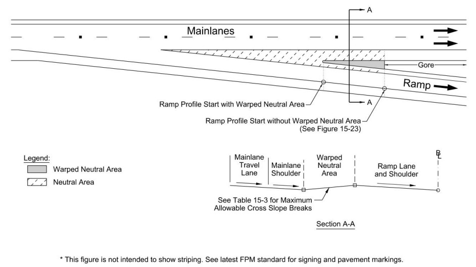
Figure 15-24: Warped Neutral Area
Design Speed of Exit or Entrance Curve (mph) | Maximum Algebraic Difference in Cross Slope at Crossover Line (%) |
Less than or equal to 20 | 5.0 to 8.0 |
25 to 30 | 5.0 to 6.0 |
Greater than or equal to 35 | 4.0 to 5.0 |
15.7.4 Cross Section and Cross Slopes
Superelevation rates, as related to curvature and design speed of the ramp or direct connector, should be based on values seen in
or
The cross section of a ramp or direct connector is a function of the following variables:
- Number of lanes determined by traffic volume;
- Minimum lane and shoulder width, see ;
- Lane balance; and
- Where traffic volumes require two lanes merging onto a freeway, adequate weaving distance must be provided.
15.7.5 Lane and Shoulder Widths.
Lane and shoulder widths for ramps and direct connectors are shown in
Inside Shoulder Width (ft.) | Outside Shoulder Width (ft.) | Lane Width (ft.) | |
1-Lane Direct Conn | 2 or 4 1 Rdwy; 41 Str | 8 | 14 |
2-Lane Direct Conn | 2 or 4 1 Rdwy; 41 Str | 8 | 12 |
Ramps (uncurbed) | 2 or 4 1 Rdwy; 41 Str | 6 to 8 | 14 2 |
Ramps (curbed) | 22 2 | ||
Notes: | |||
1. Roadways with longitudinal traffic barriers must provide a minimum 4-ft shoulder from the travel lane edge. The shoulder across a bridge will be measured from the travel lane edge to the nominal face of rail. This provides additional offset for high-speed operation and door-opening space for vehicles stopped on the shoulder of the roadway. 2. 12-ft lanes are permissible on ramps with multiple lanes. | |||
15.7.6 Sight Distance
Sufficient sight distance should be provided for the probable vehicle speeds on ramps and direct connectors taking into consideration the grade, vertical curve, alignment, and lateral and corner obstructions to vision. Sight distance and sight lines are especially important at merge points for ramps and mainlanes or between individual ramps. See
for recommended stopping sight distances for ramps and direct connections.
The sight distance on a freeway preceding the approach nose of an exit ramp should exceed the minimum stopping sight distance for the freeway design speed, preferably by 25 percent or more. For
Decision Sight Distance
, see
, for a desirable goal.15.7.7 Ramp Terminal Design
The design of ramp terminals for exits from and entrances onto freeways and frontage roads has a significant impact to safety, operation, and capacity of the freeway facility. The following ramp terminal design features are discussed:
- Entrance Ramp Acceleration Lane to Freeway;
- Taper-type Entrance Ramp to Freeway;
- Parallel-Type Entrance Ramp to Freeway;
- Entrance Ramp to Freeway on a Curve;
- Exit Ramp Deceleration Lane from Freeway;
- Taper-Type Exit Ramp from Freeway;
- Parallel-Type Exit Ramp from Freeway;
- Entrance Ramp from Frontage Road; and
- Exit Ramps to Frontage Roads.
15.7.7.1 Entrance Ramp Acceleration Lane to Freeway.
The acceleration lane associated with entrance ramps to freeway begins where the driver transitions from the ramp curvature to the flatter geometry of the speed change lane (SCL). The lane allows for acceleration and checking for gaps in the freeway traffic. The length of the acceleration lane is determined on the basis that merging vehicles should enter the through lane at a speed approximately equal to the running speed of the freeway. The acceleration lane ends at the beginning of the taper. The taper section begins where the width of the SCL becomes less than 12-ft and ends at the point where the SCL has fully merged with the freeway through lane. The taper section is not included in the length of the SCL. The factors for the calculation of the length of an acceleration lane are:
- The speed at which drivers merge with through traffic;
- The speed at which drivers enter the acceleration lane; and
- The manner of acceleration.
See
for minimum acceleration lane lengths (La) for entrance terminals applicable to both taper- and parallel-type entrances. Adjustment factors for grade effects are shown in
. Point A (shown in
) is the point where La is measured from and controls speed on the ramp. La should not start back on the curvature of the ramp unless the radius of the ramp equals 1,000-ft or more.
Before La is extended back onto the ramp past the physical nose of the gore, the actual vertical and horizontal alignments of the ramp should be analyzed to determine if acceleration above the ramp design speed can reasonably begin there.
Gap acceptance length (Lg) is defined as beginning where the traveled ways of the mainlane and ramp roadways are a minimum of 2 lateral feet apart and ending where the right edge of the ramp is 12-ft from the right edge of the through lane of the freeway. The minimum gap acceptance length is 300-ft. The value of La or Lg, whichever produces the greater distance, is suggested for use in the design of the ramp entrance.
The two general forms of entering a freeway are through a taper type and parallel type speed change lanes.
15.7.7.2 Taper-Type Entrance Ramp to Freeway
A taper-type entrance shown in
merges into the freeway with a long, uniform taper. A desirable rate of taper is approximately 50:1 to 70:1 (Design Speed:1 or DS:1) between the outer edge of the acceleration lane and the edge of the through traffic lane. The rate of taper is measured against the alignment of the mainlanes.
The geometrics should be designed in a way that drivers attain a speed that is within 5 mph of the operating speed of the freeway by the time they reach the point where the left edge of the acceleration lane joins the traveled way of the freeway.
15.7.7.3 Parallel-Type Entrance Ramp to Freeway
The parallel-type entrance ramp to freeway shown in
provides an added lane of sufficient length to enable a vehicle to accelerate to near-freeway speed prior to merging. A taper is provided at the end of the added lane.
Desirably, a ramp curve with a baseline radius of 1,000-ft or more and length of at least 200- ft should be provided in advance of the added lane. If a radius less than 1,000-ft is used drivers tend to drive directly onto the freeway without using the acceleration lane. The taper at the downstream end of a parallel-type acceleration lane should be a suitable length to guide the vehicle gradually onto the through lane of the freeway. A minimum taper length of 300-ft is required.
The length of a parallel-type acceleration lane is generally measured from the point where the left edge of the ramp travel way joins the traveled way of the freeway to the beginning of the downstream taper, Lg. Acceleration usually takes place downstream from this point. However, a part of the ramp may also be considered in the acceleration length, La, provided the ramp curve approaching the acceleration lane has a radius of 1,000-ft or more and the motorist on the ramp has an unobstructed view of traffic on the freeway to the motorist’s left.
An acceleration length, La, of at least 1,200-ft plus the taper is desirable where the ramp-freeway volume is nearing 4,600 vehicles per hour at the ramp-freeway junction.
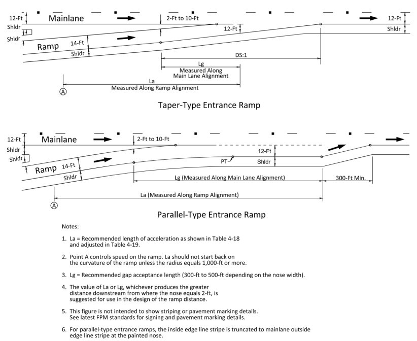
Figure 15-25: Single-Lane Entrance Ramp Terminals on a Tangent
15.7.7.4 Entrance Ramp to Freeway on a Curve
Connecting taper-type entrance ramps to freeways in a horizontal curve will need to be independently evaluated depending on the radius of the mainlanes as well as any superelevation and/or direction of the cross slope of the mainlanes, if any. Refer to
for guidance on developing the alignment of a speed change lane on curves.
through
show different cross slope and curvature combinations of an entrance ramp connecting to the mainlanes. In all scenarios, the rate of taper (DS:1) is measured against the alignment of the mainlanes. If the mainlanes are superelevated, the cross-slope transition should occur in the ramp prior to the physical nose. In the case where ramp curves are reverse of mainlanes or ramp cross slope exceed mainlane cross slope, a sufficient length of tangent or a larger compound curve must be provided on the ramp to accommodate cross slope transitions prior to the physical nose. When a taper-type entrance ramp is used in a curve, the taper should be evenly distributed throughout the curve to meet the desirable taper length.
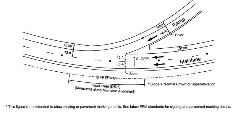
Figure 15-26: Entrance Ramp to a Freeway Curving in The Direction of The Ramp
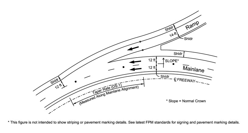
Figure 15-27: Entrance Ramp to A Freeway Curving Away from The Direction Of The Ramp
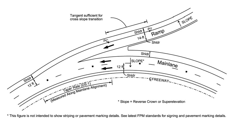
Figure 15-28: Entrance Ramp to a Superelevated Freeway Curving Away from the Ramp
15.7.7.5 Exit Ramp Deceleration Lane from Freeway
The deceleration lane associated with exit ramps from freeways is sometimes preceded by a tapered section of roadway. It begins where the speed change lane is 12-ft and ends at Point A. The deceleration lane provides a means for vehicles to decelerate from the freeway speed to a speed commensurate with the controlling feature of the ramp. The deceleration lane length (La) is based on three factors: (a) the speed at which drivers maneuver onto the auxiliary lane, (b) the speed at the end of the deceleration lane, and (c) the manner of deceleration.
15.7.7.6 Taper-Type Exit Ramp from Freeway
A taper-type exit ramp, as shown in
tangent example begins with an abrupt outer edge alignment break providing a clear indication of the point of departure from the through lanes. The divergence angle is usually 2 to 5 degrees. The angular break may be rounded by an appropriate radius at the design engineer’s discretion.
The taper-type exit may also be designed using an alignment as shown in
curvilinear example.
The divergence angle resulting from the designed alignment should be calculated and compared to the typical 2 to 5 degrees.
15.7.7.7 Parallel-Type Exit Ramp from freeway
A parallel-type exit terminal usually begins with a taper followed by an added lane that is parallel to the traveled way as shown in
. In locations where both the mainlane and ramp carry high volumes of traffic, the deceleration lane provided by the parallel-type exit provides storage for vehicles that would otherwise undesirably queue up on the through lane or on a shoulder. The length of a parallel-type deceleration lane is usually measured from the point where the added lane attains a 12-ft width to the point where the alignment of the ramp roadway departs from the alignment of the freeway. Where the ramp between the gores is curved it is desirable to provide a transition at the end of the deceleration lane.
Minimum deceleration lengths for various combinations of design speeds for the highway and for the ramp roadway are given in
. For grade adjustments see
. The values in
for minimum deceleration lane length on exit ramps do not account for any deceleration in the through lanes, therefore providing a conservative estimate for design. The designer should assume that all deceleration takes place in the speed-change lane when determining the minimum deceleration lane length.
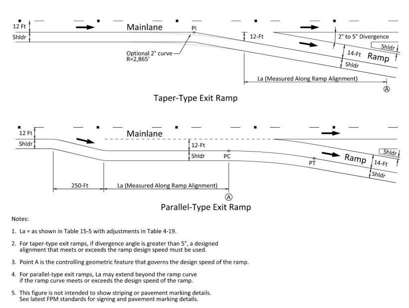
Figure 15-29: Typical Single-Lane Exit Ramp Terminals
Deceleration Lane Length, La (ft) for Design Speed of Controlling Feature on Ramp, V’ (mph) | |||||||||
Highway Design Speed, V (mph) | Stop Condition | 15 | 20 | 25 | 30 | 35 | 40 | 45 | 50 |
30 | 235 | 200 | 170 | 140 | - | - | - | - | - |
35 | 280 | 250 | 210 | 185 | 150 | - | - | - | - |
40 | 320 | 295 | 265 | 235 | 185 | 155 | - | - | - |
45 | 385 | 350 | 325 | 295 | 250 | 220 | - | - | - |
50 | 435 | 405 | 385 | 355 | 315 | 285 | 225 | 175 | - |
55 | 480 | 455 | 440 | 410 | 380 | 350 | 285 | 235 | - |
60 | 530 | 500 | 480 | 460 | 430 | 405 | 350 | 300 | 240 |
65 | 570 | 540 | 520 | 500 | 470 | 440 | 390 | 340 | 280 |
70 | 615 | 590 | 520 | 550 | 520 | 490 | 440 | 390 | 340 |
75 | 660 | 635 | 620 | 600 | 575 | 535 | 490 | 440 | 390 |
80 | 705 | 680 | 665 | 645 | 620 | 580 | 535 | 490 | 440 |
15.7.7.8 Entrance Ramp from Frontage Road
The geometry of ramps connecting from frontage roads will differ significantly depending on whether they are connecting to a one-way or two-way frontage road. Connection from one-way frontage roads is recommended, as this reduces the chance of wrong-way traffic on a ramp. The horizontal geometry of the ramp connecting from a frontage road should be equal to or more conservative than the frontage road dependent upon the context and speed, see
for appropriate superelevation methodologies.
While treatment of pavement edges may differ depending on whether the frontage road is shouldered or curbed, the path of the traffic remains the same. The traffic path should follow a smooth horizontal curve tangent to both the inside yellow stripe of the frontage road through to the inside yellow stripe of the ramp. This applies whether or not the traffic is entering from the through lanes on the frontage road or a dedicated auxiliary lane. Geometry guidance for entrance ramps from frontage roads is shown in
and
. For more geometry and access control information on entrance ramps from frontage roads, see
.
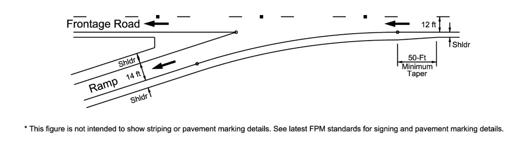
Figure 15-30: Taper-Type Entrance Ramp from a One-Way Frontage Road
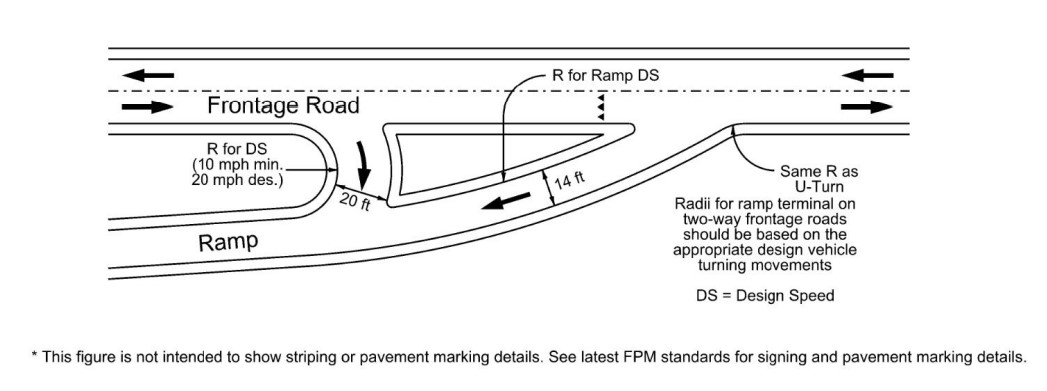
Figure 15-31: Taper-Type Entrance Ramp from a Two-Way Frontage Road
15.7.7.9 Exit Ramps to Frontage Roads
Ramps should connect to the frontage road at the minimum distance (see
). Greater distances are desirable to provide adequate weaving length, space added for vehicle storage, and turn lanes at the cross street. For more geometry and access control information on exit ramps to frontage roads, see
15.7.8 Ramp Spacing
The minimum acceptable distance between ramps is dependent upon the merge, diverge, and weaving operations that take place between ramps, as well as distances required for signing.
The minimum distance is measured from painted nose of gore to painted nose of gore as illustrated in
.
The distance between successive ramps must be determined with the analysis procedures referred to in the
. A design waiver will be required if the minimum distance for the minimum Level of Service (LOS) as determined by an HCM analysis cannot be met. Additionally, a design waiver will be required if the minimum values in
cannot be met.When the distance between the successive painted noses of an entrance-exit (EN-EX) ramp combination is less than 2,000-ft on a freeway or 1,500-ft on a collector-distributor or frontage road, then speed-change lanes should be connected to provide an auxiliary lane.
When the minimum needed distance cannot be achieved, consideration should be given to consolidating or braiding the ramps in lieu of requesting a design waiver.
Ramp configurations shown in
are relative to the facility being traveled on.
See section 15.8.1 for additional considerations on ramp spacing along frontage roads.
15.7.9 Metered Ramps
Where ramps are currently expected to accommodate metering, or expected to in the future, the geometric design features referred to in
design criteria for ramp metering should be considered. Ramp metering, when properly designed and installed, has been shown to have benefits for the operation of the mainlanes. However, since ramp meters are installed to control the number of vehicles that are allowed to enter the mainlanes, an analysis of the entire roadway network area should be done to determine adverse operational impacts to other roadways. It is suggested that the analysis specifically include both frontage road and adjacent cross street operations of through traffic, turning movements, and queue lengths. Refer to
for additional discussion and design details on ramp metering.
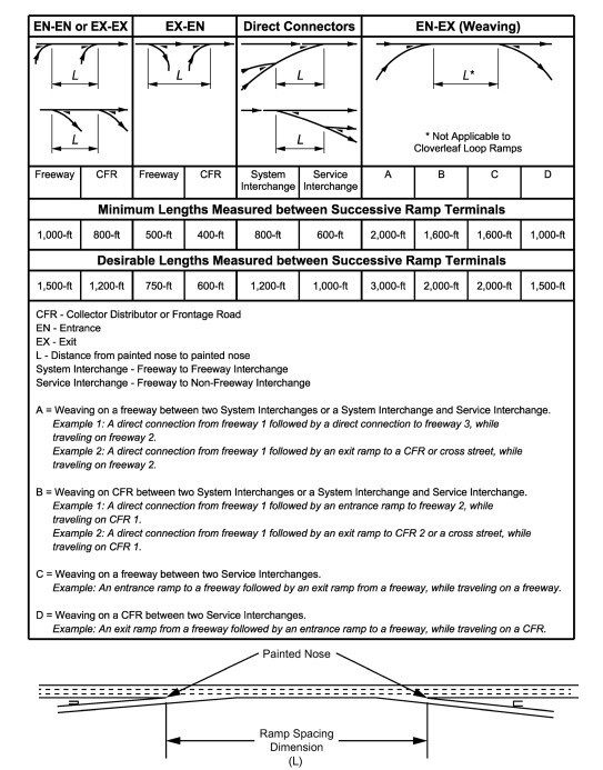
Figure 15-32: Arrangements for Successive Ramps