15.7.7 Ramp Terminal Design
The design of ramp terminals for exits from and entrances onto freeways and frontage roads has a significant impact to safety, operation, and capacity of the freeway facility. The following ramp terminal design features are discussed:
- Entrance Ramp Acceleration Lane to Freeway;
- Taper-type Entrance Ramp to Freeway;
- Parallel-Type Entrance Ramp to Freeway;
- Entrance Ramp to Freeway on a Curve;
- Exit Ramp Deceleration Lane from Freeway;
- Taper-Type Exit Ramp from Freeway;
- Parallel-Type Exit Ramp from Freeway;
- Entrance Ramp from Frontage Road; and
- Exit Ramps to Frontage Roads.
15.7.7.1 Entrance Ramp Acceleration Lane to Freeway.
The acceleration lane associated with entrance ramps to freeway begins where the driver transitions from the ramp curvature to the flatter geometry of the speed change lane (SCL). The lane allows for acceleration and checking for gaps in the freeway traffic. The length of the acceleration lane is determined on the basis that merging vehicles should enter the through lane at a speed approximately equal to the running speed of the freeway. The acceleration lane ends at the beginning of the taper. The taper section begins where the width of the SCL becomes less than 12-ft and ends at the point where the SCL has fully merged with the freeway through lane. The taper section is not included in the length of the SCL. The factors for the calculation of the length of an acceleration lane are:
- The speed at which drivers merge with through traffic;
- The speed at which drivers enter the acceleration lane; and
- The manner of acceleration.
See
for minimum acceleration lane lengths (La) for entrance terminals applicable to both taper- and parallel-type entrances. Adjustment factors for grade effects are shown in
. Point A (shown in
) is the point where La is measured from and controls speed on the ramp. La should not start back on the curvature of the ramp unless the radius of the ramp equals 1,000-ft or more.
Before La is extended back onto the ramp past the physical nose of the gore, the actual vertical and horizontal alignments of the ramp should be analyzed to determine if acceleration above the ramp design speed can reasonably begin there.
Gap acceptance length (Lg) is defined as beginning where the traveled ways of the mainlane and ramp roadways are a minimum of 2 lateral feet apart and ending where the right edge of the ramp is 12-ft from the right edge of the through lane of the freeway. The minimum gap acceptance length is 300-ft. The value of La or Lg, whichever produces the greater distance, is suggested for use in the design of the ramp entrance.
The two general forms of entering a freeway are through a taper type and parallel type speed change lanes.
15.7.7.2 Taper-Type Entrance Ramp to Freeway
A taper-type entrance shown in
merges into the freeway with a long, uniform taper. A desirable rate of taper is approximately 50:1 to 70:1 (Design Speed:1 or DS:1) between the outer edge of the acceleration lane and the edge of the through traffic lane. The rate of taper is measured against the alignment of the mainlanes.
The geometrics should be designed in a way that drivers attain a speed that is within 5 mph of the operating speed of the freeway by the time they reach the point where the left edge of the acceleration lane joins the traveled way of the freeway.
15.7.7.3 Parallel-Type Entrance Ramp to Freeway
The parallel-type entrance ramp to freeway shown in
provides an added lane of sufficient length to enable a vehicle to accelerate to near-freeway speed prior to merging. A taper is provided at the end of the added lane.
Desirably, a ramp curve with a baseline radius of 1,000-ft or more and length of at least 200- ft should be provided in advance of the added lane. If a radius less than 1,000-ft is used drivers tend to drive directly onto the freeway without using the acceleration lane. The taper at the downstream end of a parallel-type acceleration lane should be a suitable length to guide the vehicle gradually onto the through lane of the freeway. A minimum taper length of 300-ft is required.
The length of a parallel-type acceleration lane is generally measured from the point where the left edge of the ramp travel way joins the traveled way of the freeway to the beginning of the downstream taper, Lg. Acceleration usually takes place downstream from this point. However, a part of the ramp may also be considered in the acceleration length, La, provided the ramp curve approaching the acceleration lane has a radius of 1,000-ft or more and the motorist on the ramp has an unobstructed view of traffic on the freeway to the motorist’s left.
An acceleration length, La, of at least 1,200-ft plus the taper is desirable where the ramp-freeway volume is nearing 4,600 vehicles per hour at the ramp-freeway junction.
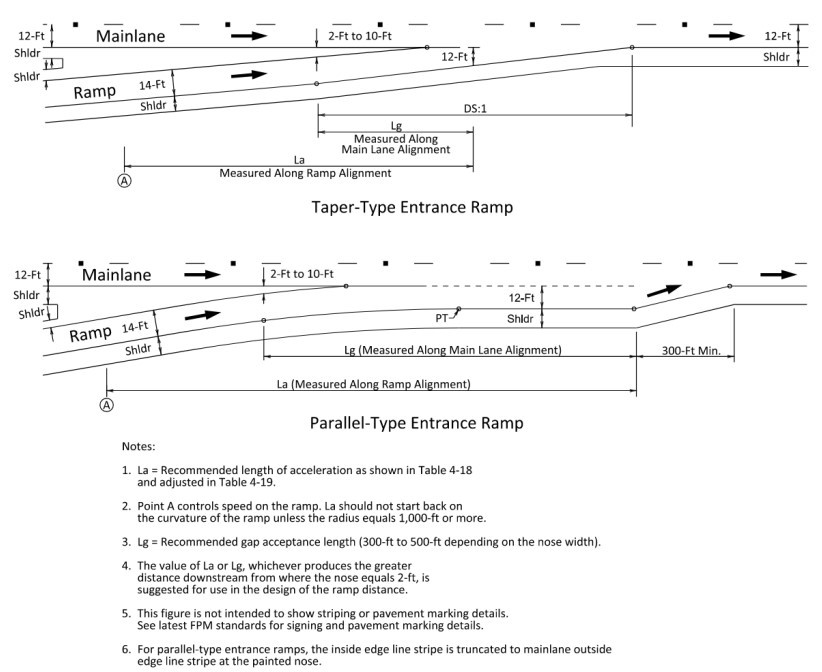
Figure 15-25: Single-Lane Entrance Ramp Terminals on a Tangent
15.7.7.4 Entrance Ramp to Freeway on a Curve
Connecting taper-type entrance ramps to freeways in a horizontal curve will need to be independently evaluated depending on the radius of the mainlanes as well as any superelevation and/or direction of the cross slope of the mainlanes, if any. Refer to
for guidance on developing the alignment of a speed change lane on curves.
through
show different cross slope and curvature combinations of an entrance ramp connecting to the mainlanes. In all scenarios, the rate of taper (DS:1) is measured against the alignment of the mainlanes. If the mainlanes are superelevated, the cross-slope transition should occur in the ramp prior to the physical nose. In the case where ramp curves are reverse of mainlanes or ramp cross slope exceed mainlane cross slope, a sufficient length of tangent or a larger compound curve must be provided on the ramp to accommodate cross slope transitions prior to the physical nose. When a taper-type entrance ramp is used in a curve, the taper should be evenly distributed throughout the curve to meet the desirable taper length.
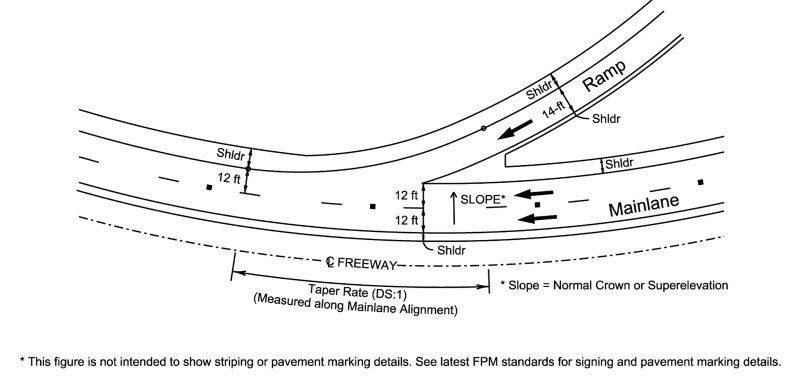
Figure 15-26: Entrance Ramp to a Freeway Curving in The Direction of The Ramp
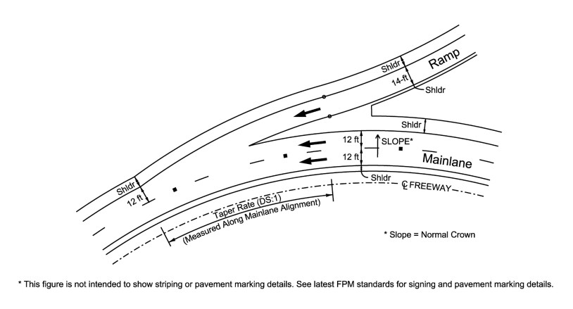
Figure 15-27: Entrance Ramp to A Freeway Curving Away from The Direction Of The Ramp
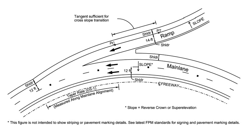
Figure 15-28: Entrance Ramp to a Superelevated Freeway Curving Away from the Ramp
15.7.7.5 Exit Ramp Deceleration Lane from Freeway
The deceleration lane associated with exit ramps from freeways is sometimes preceded by a tapered section of roadway. It begins where the speed change lane is 12-ft and ends at Point A. The deceleration lane provides a means for vehicles to decelerate from the freeway speed to a speed commensurate with the controlling feature of the ramp. The deceleration lane length (La) is based on three factors: (a) the speed at which drivers maneuver onto the auxiliary lane, (b) the speed at the end of the deceleration lane, and (c) the manner of deceleration.
15.7.7.6 Taper-Type Exit Ramp from Freeway
A taper-type exit ramp, as shown in
tangent example begins with an abrupt outer edge alignment break providing a clear indication of the point of departure from the through lanes. The divergence angle is usually 2 to 5 degrees. The angular break may be rounded by an appropriate radius at the design engineer’s discretion.
The taper-type exit may also be designed using an alignment as shown in
curvilinear example.
The divergence angle resulting from the designed alignment should be calculated and compared to the typical 2 to 5 degrees.
15.7.7.7 Parallel-Type Exit Ramp from freeway
A parallel-type exit terminal usually begins with a taper followed by an added lane that is parallel to the traveled way as shown in
. In locations where both the mainlane and ramp carry high volumes of traffic, the deceleration lane provided by the parallel-type exit provides storage for vehicles that would otherwise undesirably queue up on the through lane or on a shoulder. The length of a parallel-type deceleration lane is usually measured from the point where the added lane attains a 12-ft width to the point where the alignment of the ramp roadway departs from the alignment of the freeway. Where the ramp between the gores is curved it is desirable to provide a transition at the end of the deceleration lane.
Minimum deceleration lengths for various combinations of design speeds for the highway and for the ramp roadway are given in
. For grade adjustments see
. The values in
for minimum deceleration lane length on exit ramps do not account for any deceleration in the through lanes, therefore providing a conservative estimate for design. The designer should assume that all deceleration takes place in the speed-change lane when determining the minimum deceleration lane length.
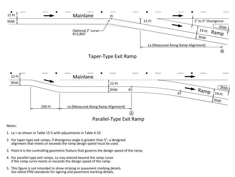
Figure 15-29: Typical Single-Lane Exit Ramp Terminals
Deceleration Lane Length, La (ft) for Design Speed of Controlling Feature on Ramp, V’ (mph) | |||||||||
Highway Design Speed, V (mph) | Stop Condition | 15 | 20 | 25 | 30 | 35 | 40 | 45 | 50 |
30 | 235 | 200 | 170 | 140 | - | - | - | - | - |
35 | 280 | 250 | 210 | 185 | 150 | - | - | - | - |
40 | 320 | 295 | 265 | 235 | 185 | 155 | - | - | - |
45 | 385 | 350 | 325 | 295 | 250 | 220 | - | - | - |
50 | 435 | 405 | 385 | 355 | 315 | 285 | 225 | 175 | - |
55 | 480 | 455 | 440 | 410 | 380 | 350 | 285 | 235 | - |
60 | 530 | 500 | 480 | 460 | 430 | 405 | 350 | 300 | 240 |
65 | 570 | 540 | 520 | 500 | 470 | 440 | 390 | 340 | 280 |
70 | 615 | 590 | 520 | 550 | 520 | 490 | 440 | 390 | 340 |
75 | 660 | 635 | 620 | 600 | 575 | 535 | 490 | 440 | 390 |
80 | 705 | 680 | 665 | 645 | 620 | 580 | 535 | 490 | 440 |
15.7.7.8 Entrance Ramp from Frontage Road
The geometry of ramps connecting from frontage roads will differ significantly depending on whether they are connecting to a one-way or two-way frontage road. Connection from one-way frontage roads is recommended, as this reduces the chance of wrong-way traffic on a ramp. The horizontal geometry of the ramp connecting from a frontage road should be equal to or more conservative than the frontage road dependent upon the context and speed, see
for appropriate superelevation methodologies.
While treatment of pavement edges may differ depending on whether the frontage road is shouldered or curbed, the path of the traffic remains the same. The traffic path should follow a smooth horizontal curve tangent to both the inside yellow stripe of the frontage road through to the inside yellow stripe of the ramp. This applies whether or not the traffic is entering from the through lanes on the frontage road or a dedicated auxiliary lane. Geometry guidance for entrance ramps from frontage roads is shown in
and
. For more geometry and access control information on entrance ramps from frontage roads, see
.
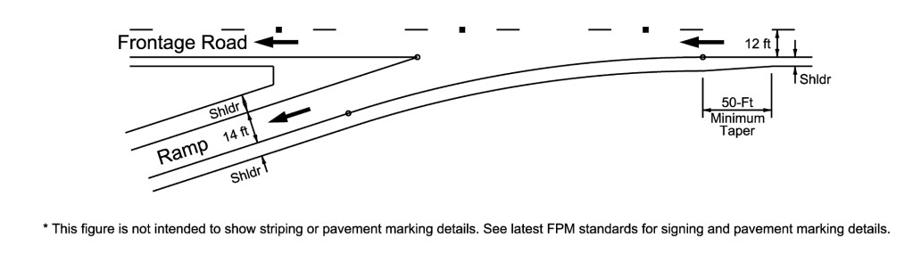
Figure 15-30: Taper-Type Entrance Ramp from a One-Way Frontage Road
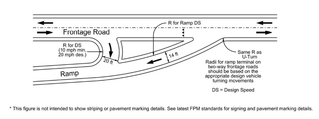
Figure 15-31: Taper-Type Entrance Ramp from a Two-Way Frontage Road
15.7.7.9 Exit Ramps to Frontage Roads
Ramps should connect to the frontage road at the minimum distance (see
). Greater distances are desirable to provide adequate weaving length, space added for vehicle storage, and turn lanes at the cross street. For more geometry and access control information on exit ramps to frontage roads, see