4.10 Cross Sectional Elements
4.10.1 Through Travel Lanes
Subsequent chapters of this manual identify appropriate lane widths for the various functional and context classifications.
4.10.2 Speed Change Lanes
Speed Change Lanes are defined as acceleration or deceleration lanes for left or right turns, exit or entrance acceleration or deceleration lanes, or a climbing lane.
A design waiver is required for speed change lanes with lengths and widths that do not meet minimum criteria as presented in Appendix B.
Speed change lanes may be provided as space for deceleration/acceleration to/from intersecting side streets with significant volumes and high operating speeds. They also provide space for deceleration and optional storage of turning vehicles. The length of speed change lanes for turning vehicles consists of the following to components:
- Deceleration length; and
- Storage length.
Design Speed (mph) | Deceleration Length (ft) 2 Speed Differential 3 | Taper Length (ft) | Minimum 6,7 Storage Length (ft) | ||
None | 5-mph 4 | 10-mph 5 | |||
30 | 150 | 105 | 70 | 50 9 | 100 |
35 | 205 | 150 | 105 | 50 9 | |
40 | 265 | 205 | 150 | 50 9 | |
45 | 340 | 265 | 205 | 100 8 | |
50 | 415 | 340 | 265 | 100 8 | |
55 | 505 | 415 | 340 | 100 8 | |
60 | 600 | 505 | 415 | 100 8 | |
65 | 700 | 605 | 515 | 150 | |
70 | 815 | 720 | 630 | 150 | |
75 | 935 | 840 | 750 | 150 | |
80 | 1060 | 965 | 875 | 150 | |
Notes: | |||||
| |||||
4.10.2.1 Width of Speed Change Lanes
The preferable width of a speed change lane should match the through lane width of the facility. In constrained situations the speed change lane width may be reduced to 11- or 10-ft on arterial and collector facilities. A design waver will be required if a width of 10-ft is not met except on local roadways. Local roadways will require a design waiver if a width of 9-ft is not provided.
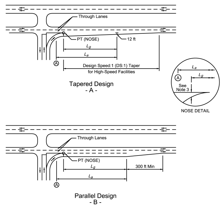
4.10.2.2 Left-Turn Deceleration Lanes
illustrates the use of left-turn lanes for all contexts. A short symmetrical reverse curve taper or straight taper may be used. For median left-turn lanes at intersections, a median divider width of 4-ft (measured to face of curb, if applicable) is recommended. Where pedestrian refuge is needed, a median divider width of 6-ft is required (measured minimum to face of curb, preferable to back of curb). If pedestrians are expected to cross the divider, then the divider should be a minimum of 5-ft wide (normal to direction of pedestrian travel) to accommodate a cut-through landing or refuge area that is at least 5-ft x 6-ft. For illustrations of these two cases, see
for additional guidance.
provides recommended taper lengths, deceleration lengths, and storage lengths for left-turn lanes. These guidelines may also be applied to the design of right-turn lanes.
For Rural roadways, adjustments to the deceleration length should be applied to a turn lane if the longitudinal grade exceeds 3 percent.
See
for adjustments factors due to steep longitudinal grades.4.10.2.2.1 Rural Left-Turn Lane Warrants
The additional expense of adding left-turn lanes on rural two-lane highways at intersecting crossroads is often not justified due to low volumes.
provides recommendations for when left-turn lanes should be considered for a typical rural two-lane highway intersection. Left-turn lanes may be added based recent crash data or projected volumes associated with planned development.
In instances on three-leg rural intersections where a left turn lane is not warranted due to low major roadway volume, but separation of through and turning traffic is still desired due to moderate to high left turn volume, a bypass lane can be installed. See
and
.
Example:
Three Leg Intersection
Left Turn Volume = 17 veh/hr
Major Road Volume = 150 veh/hr; 2 ln
Choose the next highest turn lane volume of 20 veh/h. The major road is 75 veh/h/ln, which is greater than 50, therefore a left turn lane is warranted.
Where used, left-turn lanes should be delineated with striping and pavement markers or jiggle bars. Passing should be restricted in advance of the intersection, and horizontal alignment shifts of the approaching travel lanes should be gradual.
shows typical geometry for a rural two-lane highway with left-turn bays at an intersecting crossroad.
Left-Turn Lane Peak-Hour Volume (veh/hr) | Three-Leg Intersection Major-Road Peak-Hour Volume (veh/hr/ln) for a Bypass Lane | Three-Leg Intersection Major-Road Peak-Hour Volume (veh/hr/ln) for a Left-Turn Lane | Four-Leg Intersection Major-Road Peak-Hour Volume (veh/hr/ln) for a Left-Turn Lane |
5 | 50 | 200 | 150 |
10 | 50 | 100 | 50 |
15 | < 50 | 100 | 50 |
20 or More | < 50 | 50 | < 50 |
Notes: | |||
| |||
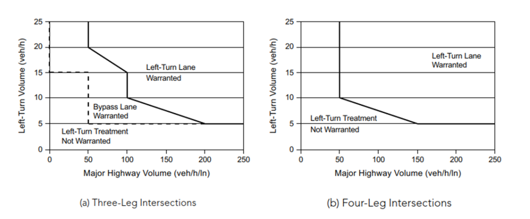
Figure 4-8: Suggested Left-Turn Warrants Based on Results from Benefit-Cost Evaluations for Intersections on Two-Lane Highways in Rural Areas
Source: AASHTO A Policy on Geometric Design of Highways and Streets
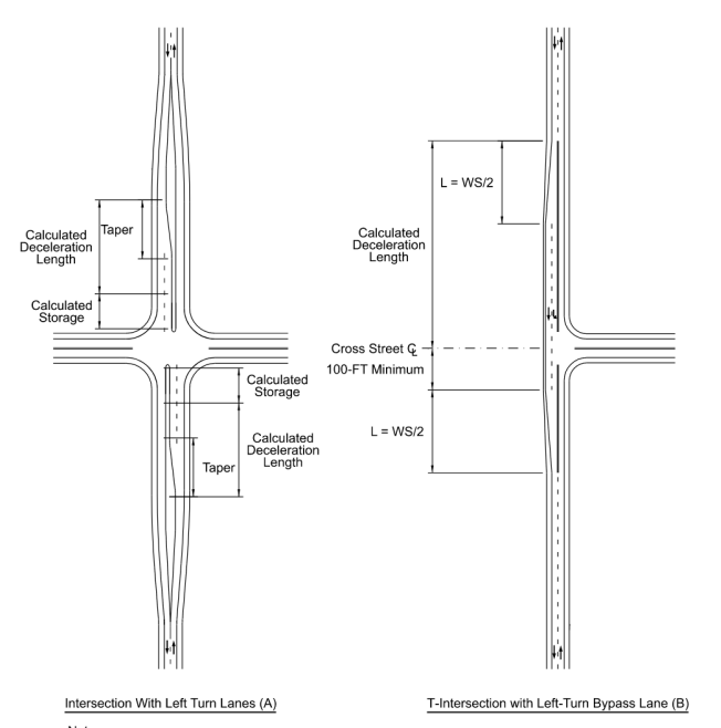
Notes:
- This is not intended to show striping or pavement marking details. refer to the Texas MUTCD for additional information.
- See Chapter 13, Intersections for additional design guidance on turn lanes.
- See Section 4.10.5 for additional design guidance on tapers.
- These figures are not intended to convey lane or shoulder widths. It is preferred to match the approach shoulder widths throughout a left-turn by-pass lane. If the shoulder width needs to be reduced for constrained situations, then it may be reduced to the minimum width for the appropriate functional classification shown in Appendix A.
Figure 4-9: Rural Two-Lane Highway with Left-Turn Bays at Intersecting Crossroad
Suggested guidelines and warrants for the installation of left-turn lanes on four-lane rural highways based on turning and through volumes is provided in
and
.
These volume-based guidelines indicate situations where a left-turn lane may be desirable, not necessarily situations where a left-turn lane is required.
Further discussion and examples of left-turn lane guidance can be found in
.Table 4-16: Guide for Left-Turn Lane Warrants for Four-Lane Highways in Rural Areas
Source: AASHTO A Policy on Geometric Design of Highways and Streets
Left-Turn Lane Peak-Hour Volume (veh/hr) | Three-Leg Intersection, Major Four-Lane Highway Peak-Hour Volume (veh/hr/ln) That Warrants a Left-Turn Lane | Four-Leg Intersection, Major Four-Lane Highway Peak-Hour Volume (veh/hr/ln) That Warrants a Left-Turn Lane |
5 | 75 | 50 |
10 | 75 | 25 |
15 | 50 | 25 |
20 | 50 | 25 |
25 | 50 | < 25 |
30 | 50 | < 25 |
35 | 50 | < 25 |
40 | 50 | < 25 |
45 | 50 | < 25 |
50 or More | 50 | < 25 |
Notes: | ||
| ||
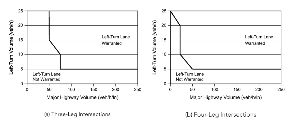
Figure 4-10: Suggested Left-Turn Warrants Based on Results from Benefit-Cost Evaluations for Rural Four-Lane Highways
Source: AASHTO A Policy on Geometric Design of Highways and Streets
4.10.2.2.2 Rural Town, Suburban, Urban, and Urban Core Left-Turn Lane Warrants
Suggested guidelines and warrants for the installation of left-turn lanes in urban and suburban areas based on turning and through volumes is provided in
and
.
These volume-based guidelines indicate situations where a left-turn lane may be desirable, not necessarily situations where a left-turn lane is required.
Further discussion and examples of left-turn lane guidance can be found in
.Table 4-17: Guide for Left-Turn Lane Warrants for Urban and Suburban Arterials
Source: AASHTO A Policy on Geometric Design of Highways and Streets
Left-Turn Lane Peak-Hour Volume (veh/hr) | Three-Leg Intersection, Major Four-Lane Highway Peak-Hour Volume (veh/hr/ln) That Warrants a Left-Turn Lane | Four-Leg Intersection, Major Four-Lane Highway Peak-Hour Volume (veh/hr/ln) That Warrants a Left-Turn Lane |
5 | 450 | 50 |
10 | 300 | 50 |
15 | 250 | 50 |
20 | 200 | 50 |
25 | 200 | 50 |
30 | 150 | 50 |
35 | 150 | 50 |
40 | 150 | 50 |
45 | 150 | < 50 |
50 or More | 100 | < 50 |
Notes: | ||
| ||
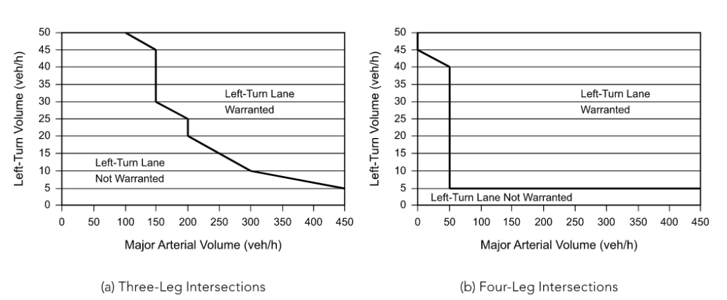
Figure 4-11: Suggested Left-Turn Warrants Based on Results from Benefit-Cost Evaluations for Intersections on Urban and Suburban Arterials
Source: AASHTO A Policy on Geometric Design of Highways and Streets
4.10.2.3 Acceleration Lanes
Acceleration lanes for right-turning or left-turning vehicles may be desirable for vehicles entering on multi-lane rural highways. Examples of both tapered and parallel accelerations lanes are shown in
. Recommended acceleration lengths are shown in
. Adjustments for grade are given in
.
- Lais the recommended acceleration length as shown in Table 4-18 or as adjusted in Table 4-19.
- Point A is the feature that controls speed on the acceleration lane. Lashould not start back on the curvature of the ramp unless the radius equals 1,000-ft or more.
- Lgis the recommended gap acceptance length. Lgshould be a minimum of 300 to 500-ft depending on nose width. (Nose width 2’-10’)
- The value of Laor Lg, whichever produces the greater distance downstream from where the nose equals 2-ft, is suggested for use in the design of the acceleration lane distance.
Figure 4-12: Examples of Tapered and Parallel Acceleration Lanes
Design Speed of Controlling Feature on Ramp (mph) | |||||||||
Highway Design Speed (mph) | Stop Condition | 15 | 20 | 25 | 30 | 35 | 40 | 45 | 50 |
30 | 180 | 140 | - | - | - | - | - | - | - |
35 | 280 | 220 | 160 | - | - | - | - | - | - |
40 | 360 | 300 | 270 | 210 | 120 | - | - | - | - |
45 | 560 | 490 | 440 | 380 | 280 | 160 | - | - | - |
50 | 720 | 660 | 610 | 550 | 450 | 350 | 130 | - | - |
55 | 960 | 900 | 810 | 780 | 670 | 550 | 320 | 150 | - |
60 | 1200 | 1140 | 1100 | 1020 | 910 | 800 | 550 | 420 | 180 |
65 | 1410 | 1350 | 1310 | 1220 | 1120 | 1000 | 770 | 600 | 370 |
70 | 1620 | 1560 | 1520 | 1420 | 1350 | 1230 | 1000 | 820 | 580 |
75 | 1790 | 1730 | 1630 | 1580 | 1510 | 1420 | 1160 | 1040 | 780 |
80 | 2000 | 1900 | 1800 | 1750 | 1680 | 1600 | 1340 | 1240 | 980 |
Deceleration Lanes | ||||||||
Design Speed of Roadway (mph) | Ratio of Length on Grade to Length on Level 1 | |||||||
3 to 4% Upgrade | 3 to 4% Downgrade | 5 to 6% Upgrade | 5 to 6% Downgrade | |||||
All | 0.9 | 1.2 | 0.8 | 1.35 | ||||
Acceleration Lanes | ||||||||
Design Speed of Roadway (mph) | Ratio of Length on Grade to Length on Level 1 for Design Speed (mph) of Turning Roadway Curve | |||||||
20 | 25 | 30 | 35 | 40 | 45 | 50 | All Speeds | |
3 to 4% Upgrade | 3 to 4% Downgrade | |||||||
40 | 1.3 | 1.3 | 1.3 | 1.3 | - | - | - | 0.7 |
45 | 1.3 | 1.3 | 1.35 | 1.35 | - | - | - | 0.675 |
50 | 1.3 | 1.35 | 1.4 | 1.4 | 1.4 | - | - | 0.65 |
55 | 1.35 | 1.4 | 1.45 | 1.45 | 1.45 | 1.45 | - | 0.625 |
60 | 1.4 | 1.45 | 1.5 | 1.5 | 1.5 | 1.55 | 1.6 | 0.6 |
65 | 1.45 | 1.5 | 1.55 | 1.55 | 1.6 | 1.65 | 1.7 | 0.6 |
70 | 1.5 | 1.55 | 1.6 | 1.65 | 1.7 | 1.75 | 1.8 | 0.6 |
75 | 1.6 | 1.65 | 1.7 | 1.75 | 1.8 | 1.9 | 2.0 | 0.6 |
80 | 1.7 | 1.75 | 1.8 | 1.9 | 2.0 | 2.05 | 2.1 | 0.6 |
5 to 6% Upgrade | 5 to 6% Downgrade | |||||||
40 | 1.5 | 1.5 | 1.5 | 1.6 | - | - | - | 0.6 |
45 | 1.5 | 1.55 | 1.6 | 1.6 | - | - | - | 0.575 |
50 | 1.5 | 1.6 | 1.7 | 1.8 | 1.9 | 2.0 | - | 0.55 |
55 | 1.6 | 1.7 | 1.8 | 1.9 | 2.05 | 2.1 | - | 0.525 |
60 | 1.7 | 1.8 | 1.9 | 2.05 | 2.2 | 2.4 | 2.5 | 0.5 |
65 | 1.85 | 1.95 | 2.05 | 2.2 | 2.4 | 2.6 | 2.75 | 0.5 |
70 | 2.0 | 2.1 | 2.2 | 2.4 | 2.6 | 2.8 | 3.0 | 0.5 |
75 | 2.15 | 2.25 | 2.35 | 2.58 | 2.8 | 3.03 | 3.25 | 0.5 |
80 | 2.3 | 2.4 | 2.5 | 2.75 | 3.0 | 3.25 | 3.5 | 0.5 |
Notes: | ||||||||
| ||||||||
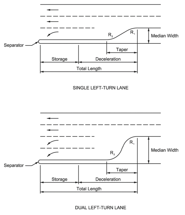
Figure 4-13: Left Turn Lane Examples (see
4.10.2.4 Deceleration Length
Deceleration length, with no speed differential, as shown in
assumes that deceleration starts at the beginning of the taper and continues to a stopped condition. Where providing this deceleration length is impractical, it may be acceptable to assume that turning vehicles will begin decelerating prior to arriving at the taper and clearing the through traffic lane. Using this assumption, see 5 mph and 10 mph speed differential columns in
for deceleration lengths.
4.10.2.5 Storage Length Calculations
The required storage may be obtained using an acceptable traffic model such as the latest version of the HCM software (HCS), SYNCHRO, or VISSIM or other acceptable simulation models. Where such model results have not been applied, the following formulas may be used:
Signalized:
Where:
L =
storage length, ft V =
left-turn volume per hour, vph Consider multiple turn lanes when V > 150. N =
number of cycles per hourRecommend between 20 and 25 cycles per hour for peak period operations if unknown.
2 =
a factor that provides for storage of all left-turning vehicles on most cyclesA value of 1.8 may be acceptable on collector streets.
S =
queue storage length, in feet, per vehicle% Trucks | S (ft) |
<5 | 25 |
5-9 | 30 |
10-14 | 35 |
15-19 | 40 |
Unsignalized:
Where:
L =
storage length, ft V =
left-turn volume per hour, vph 2 =
a factor that provides for storage of all left-turning vehicles on most cyclesA value of 1.8 may be acceptable on collector streets.
S =
queue storage length per vehicle, ft% Trucks | S (ft) |
<5 | 25 |
5-9 | 30 |
10-14 | 35 |
15-19 | 40 |
4.10.2.6 Dual Left-Turn Deceleration Lanes
For major signalized intersections where high peak hour left-turn volumes exceeding 150 vehicles per hour are expected, dual left-turn lanes should be considered. As with single left-turn lanes, dual left-turn lanes should include lengths for deceleration, storage, and taper.
provides recommended lengths for dual left-turn lanes.
4.10.2.7 Right-Turn Deceleration Lanes
illustrates a right-turn deceleration lane. The length of a single right-turn deceleration lane is the same as that for a single left-turn lane (
). However, the minimum queue storage is 30-ft for right-turn lanes.
The length for a dual right-turn lane is the same for a dual left-turn lane
(
). Refer to the
for guidelines as to when to consider a right-turn deceleration lane.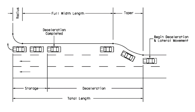
Figure 4-14: Lengths of Right Turn Deceleration Lanes
4.10.2.8 Right Turn Deceleration Lanes on Two-Lane Roadways
Shoulders 10-ft wide alongside the traffic lanes generally provide sufficient area for acceleration or deceleration of right-turning vehicles. Where the right turn deceleration or acceleration lane is being constructed adjacent to the through lanes, the minimum lane width is 10-ft with a 2-ft surfaced shoulder. Speed change lanes should be symmetrical along both sides of the highway to provide drivers with a balanced section. Refer to the
for guidelines as to when to consider a right-turn deceleration lane.
A deceleration-acceleration lane on one side of a two-lane highway, such as at a “tee” intersection, results in the appearance of a three-lane highway and may result in driver confusion. Therefore, right-turn speed change lanes are generally inappropriate for “tee” intersection design except where a four-lane section is provided. An example of this configuration is two through lanes (i.e., one through lane in each direction of traffic), one median left turn lane, and one right acceleration/deceleration lane. See
for length of deceleration lanes.
4.10.2.9 Right-Turn and U-Turn Acceleration Lanes
Acceleration lanes are generally not used on urban streets. Right-turn acceleration lanes may be appropriate on some rural highways such as high-volume highways where significant truck percentages are encountered. (see
).
provides acceleration distances and
for taper lengths if an acceleration lane is necessary. Right turn acceleration lanes that end must be yield controlled. This same concept also applies to turnaround lanes (see
).
4.10.2.10 Free Right-Turn Lanes
When an acceleration lane does not end, it is considered a free right turn lane. In these cases, stop or yield control may not be provided (see
).
Downstream access should be located so that there is adequate spacing for drivers to accelerate and weave lanes safely to access the connecting driveway or cross street. It is preferred to locate access points far enough downstream so that the acceleration distances shown in
and
are met plus the additional driveway spacing shown in the
. If this
preferred spacing cannot be met, the designer should consider a different type of right turn treatment, or the right turn lane should be yield controlled at the intersection.
A design waiver or design exception is not required if this spacing is not met. Refer to the
for driveway spacing requirements.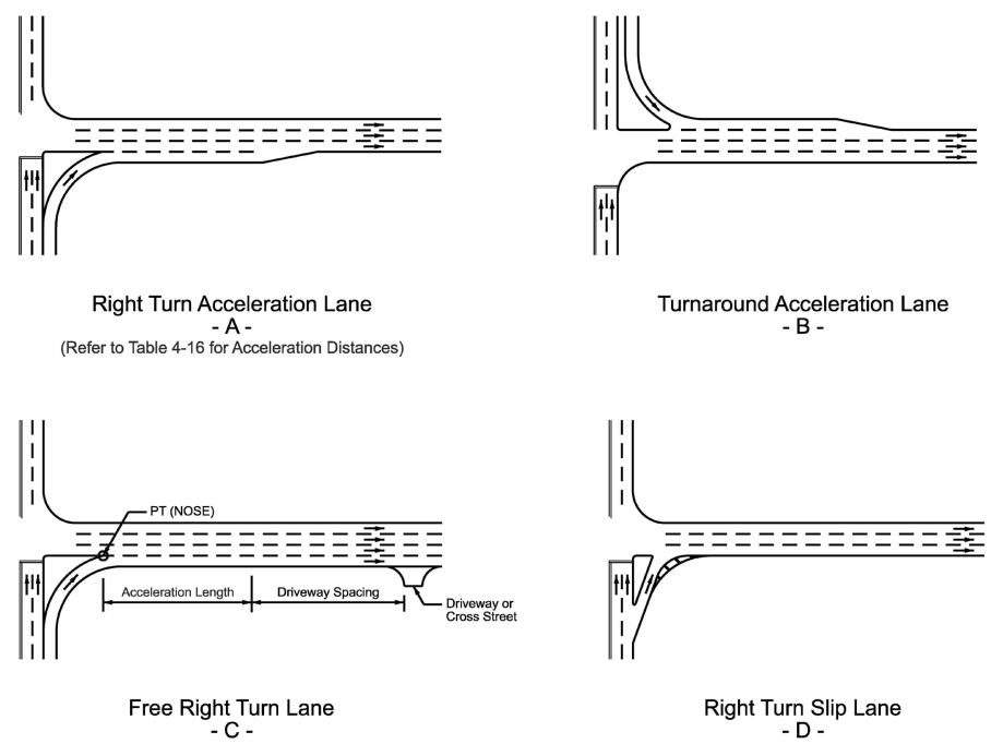
Notes:
- This is not intended to show striping or pavement marking details. Refer to the Texas MUTCD for information on striping and pavement marking details.
- Refer to Chapter 13 for additional information and guidance on Right Turn Slip Lanes. Figure A and C are not typically designed as right turn slip lanes, however there are several design elements discussed in Chapter 13 that may be incorporated for these types of right turn treatments (e.g. channelizing island, pedestrian considerations, etc.).
Figure 4-15: Types of Right Turn Treaments at Intersections
4.10.2.11 Dual-Right Turn Lanes
High volumes of right-turning vehicles may support a dual right-turn lane configuration to increase capacity for the turns while reducing delay for other movements at the intersection. Dual right-turn lanes can reduce both the length needed for the dual right-turn lanes and the corresponding green time needed for that movement. Dual right-turn movements may be in the form of either two exclusive right-turn lanes or one exclusive right-turn lane and a shared through-right-turn lane (see
).
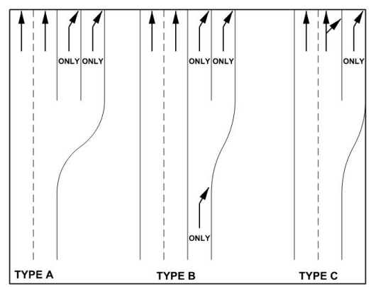
Figure 4-16: Types of Dual Right Turn Lanes
4.10.2.12 Climbing Lanes
It is desirable to provide an extra lane on the upgrade side of a two-lane highway as a climbing lane where the grade, traffic volume, and heavy vehicle volume combine to degrade traffic operations.
A climbing lane should be considered when one of the following three conditions exist:
- 10 mph or greater speed reduction is expected for a typical heavy vehicle;
- Level-of-service E or F exists on the upgrade; or
- A reduction of two or more levels of service is experienced when moving from the approach segment to the upgrade.
For low-volume roadways there is minimal delay, and a climbing lane may not be justified. For this reason, a climbing lane should only be considered on roadways with the following traffic conditions:
- Upgrade traffic flow rate is greater than 200 vehicles per hour; or
- Upgrade truck flow rate is greater than 20 vehicles per hour.
The upgrade flow rate is estimated by multiplying the anticipated or existing design hour volume by the directional distribution factor for the upgrade direction and dividing the result by the peak hour factor (see the
for definitions of these terms). To calculate the upgrade truck flow rate, multiply the upgrade flow rate by the percentage of trucks in the upgrade direction.
The beginning of a climbing lane should be introduced near the foot of the grade. The climbing lane should be preceded by a tapered section with a preferred taper ratio of 25:1 that should be at least 300-ft long
Attention should also be given to the location of the terminal point of the climbing lane. Ideally, the climbing lane should be extended to a point beyond the crest where a typical truck could reach a speed that is within 10 mph of the speed of other vehicles. In addition, climbing lanes should not end just prior to an obstruction such as a restrictive width bridge. The climbing lane should be followed by a tapered section with a ratio of 50:1.
For projects in new locations, or where an existing highway will be regraded, consider improving the grade line in lieu of providing a climbing lane. Refer to
for more information regarding the design of climbing lanes.
shows a typical section for climbing lanes on rural highways.
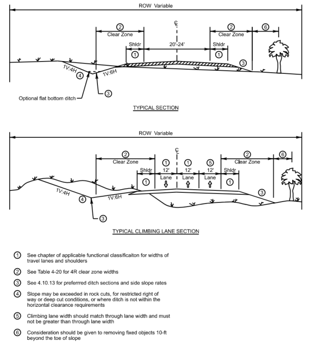
Figure 4-17: Climbing Lane Typical Section
4.10.3 Shoulders
Shoulders are of considerable value on highspeed facilities such as freeways and rural highways. Wide, surfaced shoulders provide a suitable, all-weather area for stopped vehicles to be clear of the travel lanes. Shoulders, in addition to serving as emergency parking, lend lateral support to travel lane pavement structure, provide a maneuvering area, increase sight distance of horizontal curves, and give drivers a sense of safe, open roadway. Design values for shoulder widths for the various classes of highways are shown in the appropriate subsequent portions of this manual.
Shoulders must be fully surfaced at least for the respective specified minimum width of each functional classification and context classification. Where a greater than minimum width shoulder is provided, partial (not less than minimum width) surfacing or full width surfacing may be provided at the option of the designer. The maximum cross slope of all unsurfaced shoulders must not exceed 1V:10H.
Additionally, projects must be assessed to determine if bicycle accommodations are required on the shoulder per
, they must meet the additional requirements specified in
. Bike accessible shoulders must be fully surfaced for the entire width.
Shoulder widths on bridge structures are measured from the nominal face of rail to the edge of traveled way. For additional guidance in reference to current standard bridge railings in Texas, reference TxDOT’s
and the applicable Bridge Railing Standard.
On rural town, urban and urban core collectors and local streets, parking lanes may be provided instead of shoulders. On arterial streets, parking lanes decrease capacity and generally are discouraged.
Subsequent sections of this manual identify appropriate shoulder widths for the various classes of highway and street facilities.
4.10.4 Pavement Cross Slope
The operating characteristics of vehicles on crowned pavements are such that for cross slopes up to 2 percent, the effect on steering is barely perceptible. A reasonably steep lateral slope is desirable to minimize water ponding on flat sections of uncurbed pavements due to imperfections or unequal settlement. With curbed pavements, a sufficiently steep cross slope is desirable to contain the flow of water adjacent to the curb.
The recommended pavement cross slope for usual conditions is 2 percent.
Pavement cross slopes on all roadways should not be less than 1 percent.
In areas of intense rainfall, steeper cross slopes may be used as discussed in
.
Highways with three or more lanes inclined in the same direction should desirably have an increasing cross slope as the distance from the crown line increases to facilitate pavement drainage. In these cases, the first two lanes adjacent to the crown line may be sloped flatter than normal-typically at 1.5 percent but not less than 1 percent. The cross slope of each successive pair of lanes (or single lane if that is the outside lane) outward from the crown should be increased by 0.5 to 1.0 percent from the cross slope of the adjacent lane.
A cross slope should not normally exceed 3 percent on a tangent alignment unless there are three or more lanes in one direction of travel.
Cross-slopes greater than 2 percent should be limited to use in areas of intense rainfall.
In areas of intense rainfall and where three or more lanes are provided in one direction of travel, the maximum cross slope within the tangent section of an alignment should be limited to 4 percent.
Bridge structures with three or more lanes in one direction, should maintain at least a constant slope of 2.5 percent, transitioning before and after the bridge accordingly
For tangent sections on divided highways, each pavement should have a uniform cross slope with the high point at the edge nearest the median. Although a uniform cross slope is preferable, on rural sections with a wide median, the high point of the crown is sometimes placed at the centerline of the pavement with cross slopes from 1.5 to 2 percent. At intersections, interchange ramps or in unusual situations, the high point of the crown position may vary depending upon drainage or other controls
For two-lane roadways, cross slope should also be adequate to provide proper drainage.
The cross slope for two-lane roadways for usual conditions is 2 percent and should not be less than 1 percent.
Shoulders should be sloped sufficiently to drain surface water but not to the extent that safety concerns are created for vehicular use.
The algebraic difference of cross slope between the traveled way and shoulder grades should not exceed 6 percent. Maximum shoulder slope should not exceed 10 percent.
The following are recommended cross slopes for various types of shoulders:
- Bituminous and concrete-surface shoulders on tangents should be sloped from 2 to 6 percent. Often the slope rate is identical to that used on the travel lanes, for constructability, smooth transition, and ease of use during construction and maintenance traffic control;
- Gravel or crushed rock shoulders should be sloped from 4 to 6 percent; and
- Turf shoulders should be sloped at about 8 percent.
4.10.4.1 Evaculanes
For hurricane shoulder evacuation lanes (Evaculanes) and for facilities where widening is anticipated to accommodate the ultimate typical section (i.e., using the proposed shoulders as future traffic lanes) the shoulder cross-slope should be designed in accordance with the criteria for traffic lanes. See
for additional information.
4.10.5 Pavement Taper Lengths
The following equations define minimum taper lengths where lanes and/or shoulders are reduced, opened, or shifted.
These equations define minimum taper lengths.
The project conditions (e.g., higher traffic or truck volumes) may indicate the need for additional lengths or appropriate horizontal curvature. For guidance on the length of tapers for turn lanes, acceleration lanes, or deceleration lanes, see
.
L = WS
, for S ≥ 45 mphL = WS²
/ 60, for S < 45 mphWhere:
L =
Length of taper, ft W =
Width of offset, ft S =
Posted speed, mphWhen more space is available, a longer than minimum taper distance can be beneficial.
4.10.5.1 Lane Reduction Transition Taper (L)
Lane-reduction transition tapers are used where the number of through travel lanes is reduced due to narrowing of the roadway or section of on-street parking.
The minimum length of a lane reduction transition taper is L.
4.10.5.2 Approach Taper for Obstructions (L)
Approach tapers for obstructions are used where the width of a through travel lane is reduced because of a fixed obstruction within a paved roadway. An approach taper for an obstruction is required upstream and downstream of the obstruction.
The minimum length of an approach taper for obstruction is L.
4.10.5.3 Lane-Opening Taper (½ L)
Lane-opening tapers are used where a through travel lane is added without a lateral shift of the through traffic.
The minimum length of a lane-opening taper is ½ L.
4.10.5.4 Shoulder Taper (1/3 L)
Shoulder tapers are used where the improved shoulders are reduced or increased in width.
The minimum length of a shoulder taper is 1/3 L.
Note that near the respective project termini, due to site conditions such as tying into to existing grading, drainage constraints, other site-specific circumstances or planned future project tie ins, there may be a reduction in the available length of taper (a design waiver is not required). In such circumstances an emphasis should be placed on the correct placement of pavement markings and signage indicating a reduction or elimination of the shoulder, in accordance with the
and applicable Traffic standards.
4.10.5.5 Shifting Taper
Shifting tapers are used to perform a lateral shift of the through traffic during temporary traffic control activities (i.e., construction, maintenance, and incident management). Shifting tapers should not be used to address permanent changes in horizontal alignment. When a change in horizontal alignment is required, the design criteria from
should be used.
For additional information on temporary traffic control refer to the
.
4.10.6 Rumble Strips
Centerline and shoulder rumble strips are depressed or raised patterns used to provide auditory and tactile sensations that serve as a warning mechanism when vehicles leave their respective travel lane. Transverse or in-lane rumble strips are placed perpendicular to the direction of vehicular travel and are used in very limited circumstances.
The conditions for use of rumble strips are specified in the respective
. Rumble strips have been shown to be a cost-effective countermeasure for reducing the number and severity of roadway departure crashes. As such, rumble strips have been incorporated into the Safer by Design Tool developed by TxDOT’s Council on System Safety. Additional information on the
on TxDOT.gov
4.10.6.1 Considerations for Centerline and Shoulder Rumble Strip Placement
For rural high-speed roadways, rumble strips should be installed as part of new construction, reconstruction and overlay projects, unless engineering/safety judgment determine it would be detrimental to do so. Rumble strips are recommended on high-speed urban roadways where significant numbers of crashes by frequency and percentage of total crashes due to motorist inattention have been identified (e.g., opposing direction crashes and run-off-road crashes).
Locations where rumble strips must not be placed include:
- Shoulder rumble strips across exit or entrance ramps, acceleration and deceleration lanes, crossovers, gore areas, or intersections with other roadways;
- Depressed rumble strips across bridge decks; and
- Depressed rumble strips on concrete shoulders that will be used as a permanent travel lane or a travel lane in a work zone in the near future.
4.10.6.2 Bicyclists Considerations
In all installations, appropriate riding space for bicyclists should be considered. It is preferred to allow at least 5-ft (6-ft or more desired) beyond the rumble strips to the edge of the paved shoulder. On facilities known to have considerable bicycle traffic, consider providing occasional gaps to allow bicyclists to traverse in and out of the shoulder safely. See
for additional guidance on the use of rumble strips with bicycles.
Refer to
and
for additional information.
4.10.7 Clear Zone
A clear recovery area, or clear zone, should be provided along highways. Clear zone requirements for 4R projects are shown in
. A clear zone is the unobstructed, traversable area provided beyond the edge of the through traveled way for the recovery of errant vehicles.
The clear zone includes shoulders, bicycle lanes, and auxiliary lanes, except those auxiliary lanes that function like through lanes. Such a recovery area should be clear of unyielding objects where practical or shielded by crash cushions or barrier.
The clear zone values shown in
are measured from the edge of travel lane.
These are appropriate design values for all cut sections (see
), for cross-sectional design of ditches within the clear zone area) and for all fill sections with side slopes 1V:4H or flatter.It should be noted that, while a 1V:4H slope is acceptable, a 1V:6H or flatter slope is preferred for both errant vehicle performance and slope maintainability. For slopes steeper than 1V:4H, errant vehicles have a reduced chance of recovery, therefore
it is preferable to provide an obstacle-free area of 10-ft beyond the toe of steep side slopes
even when this area is outside the clear zone.For Freeway mainlanes, or rural arterials with greater than or equal to 750 ADT, the clear zone may be limited to 30 ft. for practical purposes; however, where design speeds are 60 mph and above and side slopes are 1V:5H to 1V:4H, a clear zone of 40 ft is desirable.
Discretionary items which are items that are not necessary for the safety, maintenance, and operation of the roadway (e.g., Gateway Monuments), their foundations and any of their associated appurtenances proposed on the roadside of a facility must not be positioned within the clear recovery zone, and it is desirable that any discretionary items, their foundations and associated appurtenances be placed at least 10-ft beyond the respective minimum clear zone. If this cannot be achieved, if a more desirable alternative location is not available, and if the discretionary item must be placed within the clear zone, it must be built with appropriate breakaway supports or shielded with an appropriate crashworthy device consistent with TxDOT Roadway Standards and applications.
Context Classification | Functional Classification | Design Speed (mph) | Avg. Daily Traffic 2 | Clear Zone Width (ft) 1,3,4,5 | |
Minimum | Preferred | ||||
Rural | Freeways | All | All | 30 (16 ramp) | See 4.10.7 |
Rural | Arterial | All | ≤ 750 > 750 | 16 30 | 30 See 4.10.7 |
Rural | Collector | ≥ 50 | All | Use above rural arterial criteria. | |
Rural | Collector | ≤ 45 | All | 10 | 16 6 |
Rural | Local | All | All | 10 | 16 6 |
Suburban | All | All | < 8,000 | 10 6 | 16 6 |
Suburban | All | All | 8,000 - 12,000 | 10 6 | 20 6 |
Suburban | All | All | 12,000 - 16,000 | 10 6 | 25 6 |
Suburban | All | All | >16,000 | 20 6 | 30 6 |
Urban | Freeways | All | All | 30 (16 for ramps and collector-distributor) | |
Urban | All (Curbed) | ≥ 50 | All | Use above suburban criteria insofar as available border width permits. | |
Urban, Urban Core, Rural Town 7 | All (Curbed) | ≤ 45 | All | 4 from FOC | 6 from FOC |
Urban | All (Uncurbed) | ≥ 50 | All | Use above suburban criteria. | |
Urban, Urban Core, Rural Town 7 | All (Uncurbed) | ≤ 45 | All | 10 6 | 10 6 |
Notes: | |||||
| |||||
The designer may choose to modify clear-zone widths with adjustment factors to account for horizontal curvature, as shown in
. These modifications are mainly considered when there is a high number of crashes in the area that could be cost-effectively decreased by increasing the clear zone width. Horizontal curves, particularly for high-speed facilities, are usually superelevated to increase safety and provide a more comfortable ride. Increased superelevation on curves where the superelevation is inadequate is an alternate method of increasing roadway safety within a horizontal curve. Snow and ice should be considered in this scenario when increasing the superelevation rate.
CZ
C
= (LC
)*(KCZ
)Where:
CZC =
Clear zone on outside of curvature, ft LC =
Clear zone width, ft KCZ =
Curve adjustment factorRadius, ft | Design Speed, mph | |||||
40 | 45 | 50 | 55 | 65 | 70 | |
2,950 | 1.1 | 1.1 | 1.1 | 1.2 | 1.2 | 1.2 |
2,300 | 1.1 | 1.1 | 1.2 | 1.2 | 1.2 | 1.3 |
1,970 | 1.1 | 1.2 | 1.2 | 1.2 | 1.3 | 1.4 |
1,640 | 1.1 | 1.2 | 1.2 | 1.3 | 1.3 | 1.4 |
1,475 | 1.2 | 1.2 | 1.3 | 1.3 | 1.4 | 1.5 |
1,315 | 1.2 | 1.2 | 1.3 | 1.3 | 1.4 | - |
1,150 | 1.2 | 1.2 | 1.3 | 1.4 | 1.5 | - |
985 | 1.2 | 1.3 | 1.4 | 1.5 | 1.5 | - |
820 | 1.3 | 1.3 | 1.4 | 1.5 | - | - |
660 | 1.3 | 1.4 | 1.5 | - | - | - |
495 | 1.4 | 1.5 | - | - | - | - |
330 | 1.5 | - | - | - | - | - |
Notes: | ||||||
| ||||||
4.10.8 Lateral Offset
Lateral offset is the distance from the edge of the traveled way, beyond which a roadside object will not be perceived as an obstacle and result in a motorist's reducing speed or changing vehicle position on the roadway.
It is generally preferable that there be uniform clearance between traffic and roadside features such as bridge railings, parapets, retaining walls, and roadside barriers. In an urban environment, ROW is often limited and is characterized by sidewalks, enclosed drainage, numerous fixed objects (e.g., signs, utility poles, luminaire supports, fire hydrants, sidewalk furniture, etc.), and traffic making frequent stops.
Uniform alignment enhances highway safety by providing the driver with a certain level of expectation, thus reducing driver concern for and reaction to those objects.
The lateral offset to obstructions helps to:
- Avoid impacts on vehicle lane position and encroachments into opposing or adjacent lanes;
- Improve driveway and horizontal sight distances;
- Reduce the travel lane encroachments from occasional parked and disabled vehicles;
- Improve travel lane capacity; and
- Minimize contact from vehicle mounted intrusions (e.g., large mirrors, car doors, and the over-hang of turning trucks).
Where a curb is present, the lateral offset is measured from the face of curb (FOC) and must be a minimum of 1.5-ft. A minimum of 1-ft lateral offset should be provided from the toe of barrier to the edge of traveled way.
See
for an illustration of lateral offset minimums.
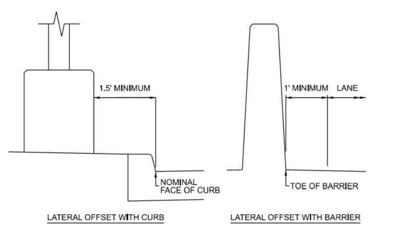
Figure 4-18: Lateral Offset Minimums
A guard fence placed in the vicinity of a curb per the current TxDOT guardrail standard does not violate the minimum lateral offset requirements.
4.10.9 Border and Outer Separation
Border
is the area between the roadway and ROW line that may serve several purposes, including but not limited to providing sight distance, a space for separation between pedestrians, bicyclists, and motor vehicle traffic; a sidewalk; or an area for underground and aboveground utilities.A portion of the border area may be used to accommodate snow storage and may include aesthetic features such as grass or landscaping.
Border widths per classification are detailed below:
- Local Roads and Streetsa minimum border of 10-ft should be utilized.
- Collectors,a border width should be at least 12-ft, including the sidewalk width.
- Arterials,a minimum border width should typically be 8-ft, but preferable of 12-ft or more depending on context and nonmotorized user needs.
- Freeways,the border should extend beyond the construction limits, where practical, to facilitate maintenance operations, and encourage an effective roadside design.
Every effort should be made to provide wide borders to serve functional needs. It should be carefully considered in the preliminary design stage to ensure that border width issues will not negatively impact PS&E preparation. For example, if 10-ft SUPs are to be installed on the outside of a pair of frontage roads, which are considered collectors, the 12-ft border width would not permit enough space for illumination or power poles, which are set 3-ft inside of the ROW lines. Utilities are just one important consideration when determining border width.
Target border widths are listed in subsequent chapters per their functional and context classifications.
Outer Separation
is the area between the traveled way of through traffic roadway and a frontage road or street.Such separations function as buffers between the through traffic on the arterial and the local traffic on the frontage road and provide space for a shoulder for the through roadway and ramp connections to or from the through facility. The wider the outer separation, the less influence local traffic will have on through traffic. Wide separations lend themselves to landscape treatment and enhance the appearance of both the highway and adjoining property. A substantial width of outer separation is particularly beneficial at intersections with cross streets because it minimizes vehicle and pedestrian conflicts.
Locations of borders and outer separation along a corridor are detailed in
.
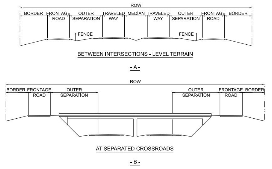
Figure 4-19: Border and Outer Separation Typical Section
Source: AASHTO A Policy on Geometric Design of Highways and Streets
4.10.9.1 Berms
There are two different types of berms typically used on urban streets. The first, constructed as a narrow shelf or path, is typically used to provide a flush grade behind a curb to accommodate the possible future installation of sidewalks. The width of the berm should accommodate a buffer between the curb and the sidewalk, the sidewalk, and any needed buffer on the backside of the sidewalk.
The second type of berm is constructed as a raised mound to facilitate drainage or for landscaping purposes. A raised mound berm should be placed outside of the clear zone, when practical. If it cannot be placed outside of the clear zone, care should be taken to ensure that the slopes and configurations of the berm meet the clear zone requirements as discussed in
.
The first and second type of berms are illustrated in
.
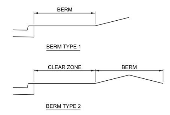
Figure 4-20: Examples of Berms
4.10.10 Right of Way Width
ROW width is the area necessary to accommodate the various cross-sectional elements, including widths of travel and turning lanes, bicycle lanes, shoulders, or parking lanes, median, borders, sidewalks, sidewalk offsets, slopes and provide ramps or connecting roadways where interchanges are involved.
The width of ROW for urban streets is influenced by the following factors:
- Traffic volume requirements;
- Land use;
- Drainage considerations;
- Utilities;
- Availability and cost; and
- Extent of expansion.
4.10.11 Roadside Design
Of particular concern in the design process is mitigating the number of single-vehicle, run-off-the-road crashes which occur even on the safest facilities. The configuration and condition of the roadside greatly affect the extent of damages and injuries for these crashes.
Increased safety may be realized through application of the following principles, particularly on high-speed facilities:
- A “forgiving” roadside should be provided, free of unyielding obstacles including landscaping, drainage facilities that create obstacles, steep slopes, utility poles, etc. For adequate safety, it is desirable to provide an unencumbered roadside recovery area that is as wide as practicable for the specific highway and traffic conditions;
- Use of higher than minimum design standards result in a driver environment which is fundamentally safer because it is more likely to compensate for driver errors. Frequently, a design that includes sight distances greater than minimum, flattened slopes, etc., costs little more over the life of a project and substantially increases safety and operations; and
- For improved safety performance, highway geometry and traffic control devices should confirm drivers' expectations. Unexpected situations (e.g., left-side ramps on freeways, sharp horizontal curvature introduced within a series of flat curves, etc.) have demonstrated adverse effects on traffic operations.
For existing highways, treatment of obstacles should be considered in the following order:
- Remove the obstacle.
- Redesign the obstacle so that it can be safely traversed.
- Relocate the obstacle to a point where it is less likely to be struck.
- Make the obstacle breakaway.
- Apply a cost-effective device to provide for redirection (longitudinal barrier) or severity reduction (impact attenuators). Barrier should only be used if the barrier is less of an obstacle than the obstacle it would protect, or if the cost of safety treating the obstacle is prohibitive.
- Delineate the obstacle (would require a design waiver).
These principles have been incorporated as appropriate into the design guidelines included herein. These principles should be examined for their applicability at an individual site based on its particular circumstances, including the aspects of social impact, environmental impact, economy, and safety.
See
for additional information.
4.10.12 Curbs and Curb/Gutter
Although curbs do not have a significant re-directional capacity, curbs are intended to discourage motorists from deliberately leaving the roadway.
Curb designs are classified as vertical or mountable.
- Vertical curbsare defined as those having a vertical or nearly vertical face 6-in or higher; and
- Mountable curbsare defined as those having a mountable face less than 6-in in height.
Mountable curbs, especially those with heights of 4-in or less, can be traversed by a motorist when necessary. A preferable height for mountable curbs at some locations may be 4-in or less because higher curbs may drag the underside of some vehicles.
Curbs are used primarily on frontage roads, crossroads, and low-speed streets in rural town, urban and urban core contexts. I
n general, curbs are not desirable along highspeed roadways.
They should not be used with high-speed through traffic lanes or ramp areas except at the outer edge of the shoulder where needed for drainage, in which case they should be of the mountable type, preferably 4-in or less in height.Refer to the current
for illustrations on the various TxDOT standard curb types.
4.10.12.1 Rural
Curbs are not generally used in rural context due to high speeds. If curbs are provided, they must be mountable and should not be closer to the traveled way than the outer edge of the shoulder.
4.10.12.2 Suburban
Curbs may be used in a suburban context. Mountable curb must be used if the design speed is 50 mph or greater.
4.10.12.3 Rural Town, Urban and Urban Core
Due to limited ROW availability usually associated with these contexts, curbs will generally be used instead of shoulders.
4.10.12.4 Curb Offsets
Curb offsets can vary from 1 to 2-ft. If a curb offset is not provided a design waiver will be required. The curb offset is always measured from the face of curb whether it is a monolithic curb section or a curb and gutter section.
See
for additional offset requirements for bicycle facilities.
Both variations of curb offsets are illustrated in
.
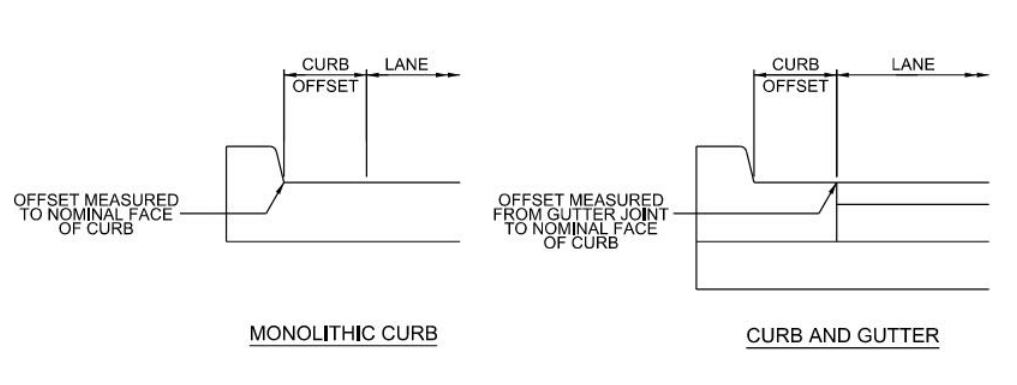
Figure 4-21: Curb Offsets Variations
4.10.13 Side Slopes
Side slopes refer to the slopes of areas adjacent to the shoulder and located between the shoulder and the ROW line. For safety reasons, it is desirable to design relatively flat areas adjacent to the travel-way so that out-of-control vehicles are less likely to turn over, vault, or impact the side of a drainage channel.
A section of typical side slopes is illustrated in
.
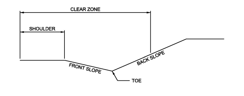
Figure 4-22: Side Slopes Section
4.10.13.1 Slope Rates
The path that an out-of-control vehicle follows after it leaves the traveled portion of the roadway is related to a number of factors such as driver capabilities, slope rates, and vehicular speed. Crash data indicates that approximately 75 percent of reported encroachments do not exceed a lateral distance of 30-ft from the travel lane edge where roadside slopes are 1V:6H or flatter - slope rates that afford drivers significant opportunity for recovery. Crash test data further indicates that steeper slopes (up to 1V:3H) are negotiable by drivers; however, recovery of vehicular control on these steeper slopes is less likely. Recommended clear zone width associated with these slopes are further discussed in 4.10.7.
4.10.13.2 Design Values
Particularly difficult terrain or restricted ROW width may require deviation from these general guide values. Where conditions are favorable, it is desirable to use flatter slopes to enhance roadside safety.
4.10.13.3 Front Slope
The slope adjacent to the shoulder is called the front slope. Ideally, the front slope should be 1V:6H or flatter, although steeper slopes are acceptable in some locations. Rates of 1V:4H or flatter facilitate efficient operation of construction and maintenance equipment. Slope rates of 1V:3H may be used in constrained conditions. Slope rates of 1V:2H are normally used on bridge header banks or ditch side slopes, both of which would likely require riprap.
Slopes greater than 1V:2.5H require evaluation for slope stability.
See TxDOT’s
for additional guidance with respect to evaluating slope stability for various conditions.When the front slope is steeper than 1V:3H, a longitudinal barrier may be considered to keep vehicles from traversing the slope.
A longitudinal barrier should not be used solely for slope protection for rates of 1V:3H or flatter since the barrier may be more of an obstacle than the slope.
Also, since recovery is less likely on 1V:3H to1V:4H slopes, fixed objects should not be present near the toe of these slopes. Particular care should be taken in the treatment of man-made appurtenances such as culvert ends. See
for additional information on considerations for barrier need.4.10.13.4 Back Slope
The back slope is typically at a slope of 1V:4H or flatter for mowing purposes. Generally, if steep front slopes are provided, the back slopes are relatively flat. Conversely, if flat front slopes are provided, the back slopes may be steeper. The slope ratio of the back slope may vary depending upon the geologic formation encountered. For example, where the roadway alignment traverses through a rock formation area, back slopes are typically much steeper and may be close to vertical.
Steep back slope designs should be examined for slope stability.
4.10.13.5 Design
The intersections of slope planes in the highway cross section should be well rounded for added safety, increased stability, and improved aesthetics. Front slopes, back slopes, and ditches should be sodded and/or seeded where feasible to promote stability and reduce erosion. In arid regions, concrete or rock retards may be necessary to prevent ditch erosion.
Where guardrail is placed on side slopes, the area between the roadway and barrier should be sloped at 1V:10H or flatter.
Roadside drainage ditches should be of sufficient width and depth to handle the design run-off, should be at least 6-in below the subgrade crown, and the design year water elevation should not backflow into the pavement structure. For additional information, see Drainage Facility Placement.
For additional information, see
.
4.10.14 Safety Edge
Straight pavement edge drop-off on roadways have been linked to many serious crashes, including fatal collisions. To mitigate the unsafe pavement drop-off a 1V:1.75H (approximately 30°) safety edge on pavements should be installed when paving or resurfacing roadway. This allows drivers who drift off highways to return to the pavement safely.
In addition to creating a safer driving surface, the safety edge also contributes to an increased pavement durability by reducing edge raveling. During design, the engineer should include the safety edge in typical sections and pavement quantities. See
for an example of a safety edge. See the
webpage for additional guidance.
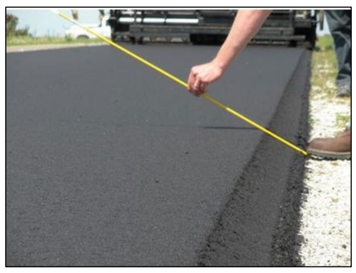
Figure 4-23: Safety Edge
4.10.15 Medians
A median (i.e., the area between opposing travel lane edges) is provided primarily on divided highways to separate opposing traffic streams. The general range of median width is from 4- to 76-ft. The design width is dependent on the context classification and traffic characteristics of the highway or street facility. When determining the minimum median width, consideration should be given to the demand for U-turn movements based on local access requirements. See
for minimum median width required to accommodate various design vehicles.
The primary functions of medians are to provide the following:
- Storage space for left-turning vehicles;
- Separation of opposing traffic streams; and
- Access control to/from minor access drives and intersections.
The types of medians that are commonly used include:
- Depressed;
- Raised;
- Flush; and
- Two-Way Left Turn Lanes (TWLTL).
4.10.15.1 Depressed Medians
Depressed medians are generally found in the rural context and will range from 48- to 76-ft in width. This type of median shares a common ditch between each side of the divided facility and offers an area for storm runoff to collect. This type of median can also provide storage space for snow during snow removal operations.
For multi-lane rural highways without access control, a median width of 76-ft is preferable to provide complete shelter for trucks at median openings. These wide, depressed medians are also effective in reducing headlight glare and providing a clear zone for run-off-the-road vehicle encroachments. They also provide a pleasing appearance and reduce chances of head on collisions. Wide medians should generally be used whenever feasible but median widths greater than 60-ft have been found to be undesirable for intersections that are signalized or may be signalized in the design life of the project. The increased time for vehicles to cross the median can lead to inefficient signal operation.
Areas that are likely to become suburban or urban in nature may require future signalization at intersections. Medians wider than 60-ft should be avoided at these intersections.
Where economically feasible, freeways in rural areas should also desirably include a 76-ft depressed median. However, since freeways by design do not allow at-grade crossings, median widths do not need to be sufficient to shelter crossing trucks. In this regard, where ROW costs are prohibitive, reduced median widths (less than 76-ft) may be used. Statistical studies have shown that over 90 percent of median encroachments involve lateral distances traveled of 48-ft or less. To account for this, unless continuous longitudinal barriers are used, depressed medians on rural freeway sections should be 48-ft or more in width.
4.10.15.2 Raised Medians
A raised median is used where it is desirable to control or restrict mid-block left turns and crossing maneuvers. Installing a raised median can result in the following benefits:
- Restricting left-turn and crossing maneuvers to specific locations or certain movements;
- Improving traffic safety;
- Increasing throughput capacity and reducing delays; and
- Providing pedestrian refuge areas.
This type of median can typically be found on roadways in the suburban, urban, or urban core contexts and may range from 4 to 36-ft in width.
On high-speed facilities, mountable curb should be used for the raised median.
A raised median design should be considered where:
- ADT exceeds 20,000 VPD;
- New development is occurring, and volumes are anticipated to exceed 20,000 VPD; or
- There are operational concerns for midblock turns.
For these conditions, a raised median may improve safety by separating traffic flows and controlling left-turn and crossing maneuvers. The use of raised medians should be discouraged where the roadway cross-section is too narrow for U-turns.
For median left turn lanes at intersections, a width of 16-ft will effectively accommodate left-turning traffic and a 4-ft median divider measured from the face of curb. However, where pedestrian refuge is a consideration for raised medians, allowances for a 6-ft width raised median, measured from the back of curb, is preferred, (6-ft measured from the face of curb is the minimum requirement). See
for additional guidance.
An 18-ft median is preferred to accommodate the 6-ft pedestrian refuge in the median, rather than providing 10-ft left turn lanes.
An illustration of this difference is shown in
.
To prevent recurring damage to the raised median divider, the divider should be at least 2- ft wide (measured from face of curb to face of curb). If pedestrians are expected to cross the divider, then the divider should be a minimum of 5-ft wide (normal to direction of pedestrian travel) to accommodate a cut-through landing or refuge area that is at least 5-ft x 6-ft.
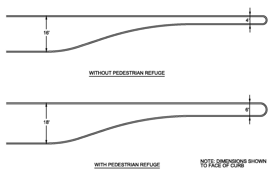
Figure 4-24: Median Left Turn Lanes with and without Pedestrian Refuge
4.10.15.3 Flush Medians
Flush medians are medians that can be traversed. A flush median cannot prevent left-turn and cross maneuvers since it can be easily crossed and cannot physically prevent these types of movement. Therefore, for roadways where access control is desirable, flush medians should not be used. When flush median designs are selected, it should be expected that some crossing and turning movements can occur in and around these medians. Full pavement structure designs will usually be carried across flush medians to allow for traffic movements.
A flush median design should include the following:
- Delineation from through lanes using double yellow stripes and possibly a contrasting surface texture or color to provide visibility; and
- Flexibility to allow additional left-turn bay storage if necessary.
This type of flush median is generally located on roadways in the rural or suburban contexts with roadside development and may range from 4- to 16-ft in width. 4-ft wide flush medians provide little separation of opposing traffic and minimal refuge area for pedestrians. 14- to 16-ft wide flush medians offer space for traffic turning left but does not offer protection for crossing vehicles.
Urban and suburban freeways generally include narrower, flush medians with continuous longitudinal barriers. The median width may vary from 24- to 30-ft, with 24-ft commonly used. See
for recommendations on the use of median barriers. See
for additional information on freeway medians.
4.10.15.4 Two-Way Left-Turn Lanes
TWLTL are flush medians that may be used for left turns by traffic from either direction on the roadway. The TWLTL is appropriate where there are operational concerns for a high frequency of mid-block turns exist or are anticipated, such as areas with (or expected to experience) moderate or intense strip development. Used appropriately, the TWLTL design can improve the safety and operational characteristics of streets as demonstrated through reduced travel times and crash rates. Recommended median lane widths for the TWLTL design are as shown in
. When applying this criterion to new location projects or on reconstruction projects the corresponding preferable width should be used where widening necessitates the removal of exterior curbs. Minimum values shown in
are appropriate for restrictive ROW projects and improvement projects where attaining the desirable width would necessitate removal and replacement of exterior curbing to gain a small amount of roadway width.
Design Speed (mph) | Width of TWLTL (ft) | |
Preferable 1 | Minimum | |
≤ 40 | 14 | 11 |
45 or 50 | 14 | 12 |
>50 | 16 | 14 |
Notes: | ||
| ||
A site can be considered suitable for the use of a TWLTL when the facility meets the following criteria:
- Future ADT volume of greater than:
- 3,000 VPD for an existing two-lane facility,
- 6,000 VPD for an existing four-lane facility, or
- 10,000 VPD for an existing six-lane facility; and
- Side roads plus driveway density of 20 or more entrances per mile for both directions of travel for urban context or 10 or more entrances per mile for both directions of travel for suburban context.
All cross sections should be evaluated for pedestrian crossing capabilities. See
for additional guidance.
4.10.15.5 Median Openings
For rural town, suburban, urban, and urban core contexts, median openings should only be provided for street intersections or at intervals for major developed areas. Spacing between median openings must be adequate to allow for introduction of left-turn lanes and to prevent false calls at signal detection loops.
As the number of median openings increase, the interference between through traffic and turning traffic increases. To reduce the conflicts between turning traffic and through traffic, turn bays should be provided at all median openings. Recommended minimum median opening spacings are based on the length of turn bay required.
Directional openings, pictured in
, can be used to limit the number and type of conflicts.
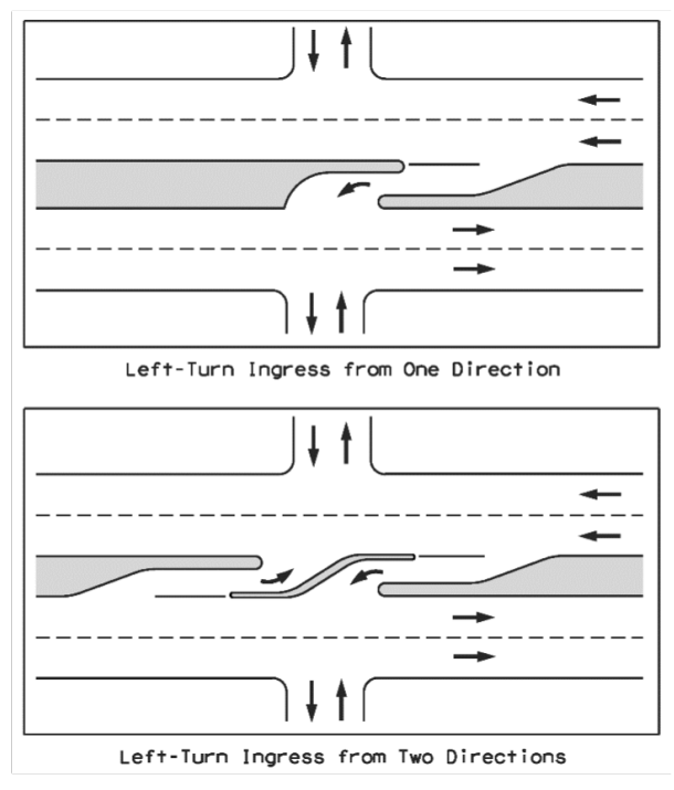
Figure 4-25: Types of Directional Openings
The positive offset design shown in
can improve the sight distance for left-turning vehicles where there are opposing left-turn lanes. This design has also been found to substantially reduce the frequency of left-turn crashes compared to negative (a) or no offset (b) designs and is desirable for use where practical. Further discussion and examples of offset left-turn lanes can be found in
.
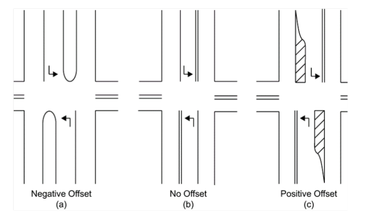
Figure 4-26: Examples of Left-Turn Lanes with Negative, Zero, and Positive Offset
Source: AASHTO’s A Policy on Geometric Design of Highways and Streets
An important factor in designing median openings is the shape of the median end or median nose. The median end shape can directly alter the effective turning path the design vehicle can make.
The shape of a median nose should be designed to accommodate the turning path of the design vehicle.
One form of a median end at an opening is a semicircle, which is a simple design that is satisfactory for median widths less than 10-ft wide. One alternate median end design that fits the paths of design vehicles is a bullet nose. The bullet nose is formed by two symmetrical arcs with a small radius to round the nose.
See
for an illustration of these two types of median ends.
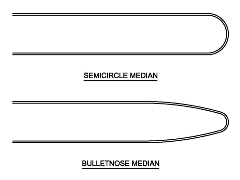
Figure 4-27: Types of Median Ends
Consider the use of local design standards for median noses where available. In the absence of a local standard refer to Chapter 9 of
for more information regarding the design of median openings.
On rural divided highways, closely spaced median openings can cause interference between high-speed through-traffic and turning vehicles. The frequency of median openings varies with topographic restrictions and local requirements. As a general rule,
the minimum spacing should be one-quarter mile or greater in rural areas.
It is typical to provide median openings at all public roads and at major traffic generators such as industrial sites or shopping centers. Additional openings should be provided to maintain a maximum one-half mile spacing.As shown in
, rural divided highways should provide left-turn lanes at all median openings and right-turn deceleration and acceleration lanes should be considered at intersections with highways or other major public roads with significant turning movements. See TxDOT’s
“Auxiliary Lanes” section and related table for additional considerations and warranting thresholds for right-turn deceleration and acceleration lanes as well as left-turn deceleration lanes at median openings.
For divided highways with independent mainlane alignment, particular care should be exercised at median openings to provide a satisfactory profile along the crossover with flat approaches to the mainlanes.
For divided highways with independent mainlane alignment, particular care should be exercised at median openings to provide a satisfactory profile along the crossover with flat approaches to the mainlanes.
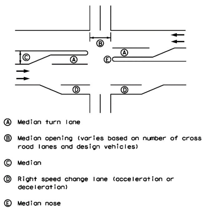
Figure 4-28: Multi-Lane Rural Highway Intersection
Median openings should be at least 40-ft wide, or the width of the crossroad pavement plus 8-ft.
Design vehicles are often used as the basis for minimum design of median openings, particularly for multilane crossroads and skewed intersections.
See
for additional information.4.10.15.6 Median Encroachment Design Guidance and Countermeasures
Median encroachment countermeasures should be considered where appropriate. High severity injuries and fatalities are a result of cross median crashes on high-speed roadways. Reducing median encroachment reduces cross median crashes and fixed object crashes in the median. The following guidelines below are for reducing the frequency and severity of median related crashes on divided highways:
Design Guidance to Reduce Consequences of Median Encroachments:
- Minimize potential for collision with fixed objects:
- Relocate or remove fixed objects in median.
- Reduce consequences of collision with fixed objects:
- Provide barrier to shield objects in median.
- Reduce likelihood of cross-median collisions:
- Provide wider median; and
- Provide continuous median barrier.
- Reduce likelihood of vehicle overturning:
- Flatten median slopes;
- Provide U-shaped (rather than V-shaped) median cross section; and
- Provide barrier to shield steep slopes.
- Improve design of geometric elements:
- Provide wider median;
- Minimize sharp curves with radii less than 3,000 feet; and
- Minimize steep grades of four percent or more.
- Improve design of mainline ramp terminals:
- Increase separation between onramps and off-ramps.
- Minimize left-side exits:
- Improve design of merge and diverge areas by lengthening speed-change lanes;
- Simplify design of weaving areas; and
- Increase decision sight-distance to on-ramps.
Countermeasures to Reduce Likelihood of Median Encroachments:
- Reduce driver inattention:
- Provide edge-line or shoulder rumble strips.
- Decrease side friction demand:
- Improve/restore superelevation at horizontal curves.
- Increase pavement friction:
- Provide high-friction pavement surfaces.
- Reduce high driver workload:
- Improve visibility and provide better advance warning for onramps;
- Improve visibility and provide better advance warning for curves and grades; and
- Improve delineation.
- Encourage drivers to reduce speeds:
- Provide transverse pavement markings.
- Minimize weather-related crashes:
- Provide weather-activated speed signs;
- Provide static signs warning of weather conditions (e.g., bridge freezes before road surface);
- Apply sand or other materials to improve road surface friction;
- Apply chemical de-icing or anti-icing as a location-specific treatment;
- Improve winter maintenance response times; and
- Raise the state of preparedness for winter maintenance.
4.10.16 Parking
This section discusses the features and design criteria for parking facilities and includes the following subsections:
- Fringe parking lots; and
- Parking along highways and arterial streets.
4.10.16.1 Fringe Parking Lots
Fringe parking lots are congestion mitigation and energy conservation measures utilized by TxDOT. Depending on the function which they are intended to serve, they may be one of the following types of facilities:
- Park and pool lots;
- Park and ride lots; and
- Combination park and pool/park and ride lots.
4.10.16.2 Park and Pool Lots
Park and Pool lots are usually located on the fringe of an urban area along an arterial roadway at a convenient point where a group of two or more drivers from a surrounding area can gather, leave their individual vehicle, and proceed to a common destination in one of the group member’s vehicles. The carpool may consist of two or more persons per vehicle. The lot may provide space for a small to large number of vehicles and serve many carpools involving several destinations.
Park and pool lots are located within the highway ROW except where they may be in combination with a park and ride lot as discussed below. They are eligible for Federal-aid participation. The lots should be simply designed to accommodate the passenger vehicle with regard to parking stall widths, drive through isles, and turning movements.
4.10.16.3 Park and Ride Lots
Park and Ride lots are generally constructed along express bus routes and are designed to intercept automobiles from low-density suburban developments along transitway corridors. The quality of transit service must be attractive. The time required to reach the destination point by bus must be comparable to or better than driving one’s own vehicle.
The facility should be located with regard to the following criteria:
- Along a corridor which encounters 20,000 vehicles per day, per lane;
- In advance of the point where intense traffic congestion routinely occurs;
- 4 to 5 miles from the activity center (usually the Central Business District) served by the transitway and at least 4 to 5 miles from another park and ride facility;
- Downstream from, but in the immediate area of, sufficient demand for travel to the activity center being served; and
- On the right-hand side of the inbound roadway.
Other desirable features include the following:
- Good accessibility to the adjoining street system;
- No parking fees;
- Space for future expansion; and
- Fencing.
Typical park and ride layouts include the following design features:
- Bus travel area designed to accommodate the anticipated type of bus for all turning movements;
- Bus loading areas located to reduce conflict between buses and private vehicles;
- Maximum walking distance of 650-ft;
- Bus access points separate from private vehicle access points if demand exceeds 500 all-day spaces;
- Parking placed in the following order with respect to proximity of the bus loading area:
- Disabled persons;
- Bicycles;
- Motorcycles;
- Vehicles of park and ride users; and
- Private vehicular parkin
- Ingress and egress located near midblock on collector and local streets; direct access to arterials and freeway ramps should only be used if projected queues do not interfere with functional areas of nearby intersections; at least two ingress/egress points should be provided to the park and ride facility; right and left turn lanes with adequate storage should be added to all ingress/egress locations;
- Parking lanes in the park and ride lot placed approximately 90 degrees to the bus loading area to facilitate safe, convenient walking to buses; and
- Curbs depressed and wheelchair ramps provided where necessary; disabled parking spaces and pedestrian facilities should be in accordance with Americans with Disabilities Act Accessibility Guidelines and Texas Accessibility Standards.
Combination Park and Pool/Park and Ride Lot
These combination type lots serve the purposes and combine the features of each of the two types of facilities discussed above.
Authority and Funding
For fringe parking areas within highway ROW, projects are generally developed as any other multiple use project. When parking lots are proposed outside of existing or proposed highway ROW, commission approval is required.
Park and pool lots are eligible for Federal-aid participation. Projects are usually located within or adjacent to highway ROW outside the central business district, but inside the urbanized area, and consistent with the urban transportation planning process. Operation and maintenance responsibilities should be assigned to local transit, government, or other agencies by agreement.
4.10.16.4 Parking Along Freeways and Arterial and Collector Streets
This section deals with parking as it pertains to the frontage roads of a controlled access highway and parking along urban and suburban arterials and collectors. Off-street parking facilities provided within highway ROW are discussed in the previous
. Rest areas as parking facilities are not considered in this section.
4.10.16.4.1 Emergency Parking
Parking on and adjacent to the mainlanes of a controlled access highway will not be permitted except for emergency situations. It is of paramount importance that provisions be made for emergency parking. Shoulders of adequate design provide for this required parking space.
4.10.16.4.2 Curb Parking
In general, curb parking on arterial and collector streets and frontage roads should be discouraged. Where speed is low and the traffic volumes are well below capacity, curb parking may be permitted. However, at higher speeds and during periods of heavy traffic movement, curb parking is incompatible with arterial street service and should not be permitted. Curb parking reduces capacity and interferes with free flow of adjacent traffic. Elimination of curb parking can increase the capacity of four-to-six lane arterials by 50 to 60 percent.
If curb parking is used on urban/suburban arterials, collectors or frontage roads under the conditions stated above, the following design requirements should be met:
- Provide parking lanes only at locations where needed;
- Parallel parking preferred;
- Confine parking lanes to outer side of street or frontage road;
- Require that parking lane widths be 10- ft.;
- 12- to 14-ft parking lane widths should be provided if bicyclists, as well as parked vehicles, need to be accommodated; and
- Restrict parking a minimum of 20-ft back from the radius of the intersection to allow for sight distance, turning clearance and, if desired, a short right turn lane.
4.10.16.5 Parking Along Local Roads
Parking along local roads in the rural and suburban contexts is not permitted.
Curb parking lane widths in rural town, urban and urban core contexts should be 8- to 9-ft. In non-commercial and non-industrial areas, a 7-ft minimum width may be used.
4.10.17 Retaining Structures
Retaining structures are used where vertical drops create lateral earth pressure. Examples of these structures include gravity walls, cantilevered walls, and mechanically stabilized earth walls.
Retaining structures contain and support soil where loadings may otherwise cause the soil to move and impact the structure supported by it. Depending on the location and specifications, these structures may be concrete or altered soil. Refer to TxDOT’s
for additional information on geotechnical design for retaining structures.
Selection of retaining structures will depend on factors such as ROW limitations, foundation soil characteristics, loading requirements, economic feasibility, and aesthetics. Whether the section is in cut or fill should also be considered, as some retaining structures are better suited for one or the other.
In situations where a roadway is elevated along a retaining wall, the drop off condition must be protected for the entire length of the wall, regardless of if the retaining wall is inside or outside the clear zone. Refer to TxDOT’s
for additional information on protection requirements for a roadway elevated along a retaining wall.
A more detailed discussion on design calculations and geometric specifics can be found in the
.
4.10.18 Utilities and Easements
Where utility work extends beyond the ROW boundaries, easements may be used to accommodate those activities. These easements may either be perpetual or temporary, depending on the work being done and expected maintenance once the work is completed.
Title reports and easement documents should be obtained and reviewed to determine boundaries and specifics of property rights of parcels and utilities affected by proposed work.
Compensation for utility adjustments may be affected not only by easements, but also by the ratio of the utility which exists within or outside of the easement and existing ROW.
For more information regarding utilities in relation to ROW and easements, refer to TxDOT’s
.