Chapter 8: Freeways (4R)
8.1 Design Considerations
8.1.1 Introduction
Freeways are arterial highways with full control of access. They are intended to provide high levels of safety and efficiency in the movement of large volumes of traffic at high speeds.
Freeways may be provided in both rural and urban areas. All freeways in rural areas are designed for the rural context; the rural town context is generally not applicable to freeways.
Freeways in urban areas may be provided to fit all contexts including suburban, urban, and urban core.
Design criteria presented in this chapter is applicable to new construction of freeways, reconstruction of existing freeways and the conversion from a non-access controlled arterial to a freeway.
This chapter discusses the features and design criteria for freeways and includes the following sections and subsections:
8.1 Design Considerations
- 8.1.1 Introduction;
- 8.1.2 Target Design Values;
- 8.1.3 Design Speed;
- 8.1.4 Design Traffic Volumes;
- 8.1.5 Level of Service;
- 8.1.6 Travel Lane Width and Number of Lanes;
- 8.1.7 Shoulders;
- 8.1.8 Speed Change Lanes;
- 8.1.9 Medians;
- 8.1.10 Curbs;
- 8.1.11 Cross Slope and Superelevation;
- 8.1.12 Grades;
- 8.1.13 Roadside Design;
- 8.1.14 Structures;
- 8.1.15 Vertical Clearance;
- 8.1.16 Ramps and Terminals;
- 8.1.17 Outer Separations and Borders;
- 8.1.18 Frontage Roads;
- 8.1.19 Collector-Distributor Roads;
- 8.1.20 Crossing Facilities;
- 8.1.21 Access Control;
- 8.1.22 Managed Lanes and Toll Facilities; and
- 8.1.23 Tunnels.
8.2 Rural Design Elements
- 8.2.1 General Design Considerations
8.3 Suburban Design Elements
- 8.3.1 General Design Considerations
8.4 Urban Design Elements
- 8.4.1 General Design Considerations;
- 8.4.2 Depressed Freeways;
- 8.4.3 Elevated Freeways;
- 8.4.4 Ground Level Freeways;
- 8.4.5 Combination-Type Freeways; and
- 8.4.6 Special Freeway Designs.
8.5 Urban Core Design Elements
- 8.5.1 General Design Considerations
This chapter is organized with an introductory section on the general design considerations for freeways, followed by separate design discussions for freeways in urban, urban core, suburban, and rural contexts.
8.1.2 Target Design Values
The subsections following
provide additional detailed discussions for each design element and factors that may influence these values.
The design value thresholds for design exceptions and design waivers are presented in
and
respectively.
Design Element | Rural | Suburban | Urban | Urban Core | Reference | ||
|---|---|---|---|---|---|---|---|
Roadway |  | Design Speed 1 | 75 MPH | 70 MPH | 65 MPH | 60 MPH | See 8.1.3 |
| Lane Width | 12-ft | See 8.1.6 | ||||
| Inside Shoulder Width (4-Lane Divided) | 8-ft | See 8.1.7 | ||||
| Inside Shoulder Width (6-Lane or More Divided) | 12-ft | See 8.1.7 | ||||
| Outside Shoulder Width | 12-ft | See 8.1.7 | ||||
 | Speed Change Lane - Lane Width - Shoulder Width | 12-ft 10-ft | See 8.1.8 See 8.1.8 | ||||
| Median Width | Varies | See 4.10.15 and 8.1.9 | ||||
| Horizontal Curve Radius (Minimum) | See 4.7 | |||||
| Cross Slope on a Tangent (Typical) | 2% | See 4.10.4 | ||||
| Cross Slope on a Tangent (Maximum) | 3% | See 4.10.4 | ||||
| Superelevation Rate (Maximum) | See Table 4-3, Table 4-6, and Table 4-7 | See 4.7.3 | ||||
Minimum Grade | 0.25% (lined ditch channels), 0.3% (curbed facilities), or 0.5% (unpaved ditches) | See 4.8.1 | |||||
| Maximum Grade (Level) | 3% | See 4.8.1 | ||||
| Maximum Grade (Rolling) | 4% | See 4.8.1 | ||||
| Vertical Clearance | 18.5-ft | See 4.8.6, and 21.2 | ||||
| Design Loading Structural Capacity | HL-93 | See 8.1.14 | ||||
| Stopping Sight Distance | See 4.11.1 | |||||
Design Vehicle | WB-67 | See 4.3.2 | |||||
Level of Service (LOS Design Year) | B | C | C | C | See 8.1.5 | ||
Roadside | | Clear Zone | See Table 4-20 | See 4.10.7 | |||
Outer Separation | Varies | See 8.1.17 | |||||
Notes | | Denotes that this is a design exception condition if the specified values in Appendix A are not met. | |||||
| Denotes that this is a design waiver condition if the specified values in Appendix B are not met. | ||||||
1. | The selected Design Speed should meet the anticipated target speed of the facility during non-peak hours. | ||||||
8.1.3 Design Speed
The design speed of freeways should reflect the anticipated operating conditions during non-peak hours.
However, the design speed should not exceed the limits of prudent construction, right of way (ROW) constraints, and socioeconomic costs. Minimum design speeds for freeways are shown in Appendix A.See
for additional guidance on selecting the appropriate design speed.
When determining applicable radii and superelevation for design speeds see
for a summary of superelevation methodologies to be used.
8.1.4 Design Traffic Volumes
Freeway projects in both rural and urban areas should be designed to accommodate traffic projections for a 20-year period into the future (mainlanes only). However, some elements (i.e., ramps, direct connections, frontage roads, and collector-distributor roads) may be based on shorter or longer design periods. For additional guidance on the selection of the appropriate periods for forecasting design traffic volumes, see
or refer to
.
Segments of freeways may be constructed or reconstructed to be proportionate with intermediate traffic demands or with traffic based on the completed system, whichever may be more appropriate.
8.1.5 Level of Service
For acceptable degrees of congestion, urban freeways, and their auxiliary facilities should generally be designed for Level of Service (LOS) C or better in the design year and can be referred to in the
. In heavily developed urban, or urban core contexts, LOS D may be acceptable. In heavily congested areas, other Measures of Effectiveness (MOEs) may include travel time, speed and queue lengths.
In rural areas, LOS B is desirable for freeway facilities; however, LOS C may be acceptable for auxiliary facilities (i.e., ramps, direct connections, frontage roads, and collector-distributor roads) carrying unusually high volumes.
8.1.6 Travel Lane Width and Number of Lanes
The minimum and usual main lane width is 12-ft. The number of lanes required to accommodate the anticipated traffic in the design year is determined by the level of service evaluation as discussed in the
. However, at a minimum, a freeway should have two through-traffic lanes in each direction of travel. See
for further information.
shows an alternative freeway section. The geometric dimensions shown in these figures represent examples of different conditions and may be adjusted in accordance with
.
8.1.6.1 Principle of Lane Balance
After the number of lanes has been determined, the balance in the number of lanes should be confirmed based on the following principles:
- At entrance ramps, the number of lanes on the highway beyond the ramp should be equal to the total number of approach lanes on the highway and the lanes on the ramp, minus one. However, it can be equal to the total number of highway approach and ramp lanes;
- At exit ramps, the number of approach lanes on the highway should be equal to the sum of all lanes on the highway beyond the ramp and the lanes on the exit ramp, minus one. Exceptions to this principle occur at clover leaf loop-ramp exits that follow a loop-ramp entrance and at exits between closely spaced interchanges. (Closely spaced interchanges are those where the distance between the end of the entrance terminal taper and the beginning of the taper of the exit terminal is less than 1,500- ft, and a continuous auxiliary lane between the terminals is provided). In these cases, the auxiliary lane may be dropped in a single-lane exit such that the number of lanes on the approach roadway is equal to the number of through lanes beyond the exit plus the lane on the exit;
- The traveled way of the highway should be reduced by not more than one traffic lane at a time;
- To satisfy lane-balance at two-lane exits, an auxiliary lane upstream of the exit should be provided; and
- To satisfy lane-balance at two-lane entrances, at least one additional lane should be provided downstream. This lane may be another through lane if needed for capacity or an auxiliary lane that may be reduced with the appropriate taper or at the next interchange.
Typical examples of lane balance are shown in
.
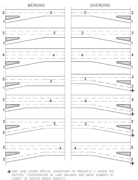
Figure 8-1 Typical Examples of Lane Balance
8.1.6.2 Left and Right Lane Drops
Sometimes it is necessary to reduce, or end, the number of through-travel lanes. When doing so, it is desirable to perform a lane drop at an exit ramp or a route split. When a lane reduction cannot take place at an exit ramp or route split, the lane reduction should occur in the outermost right through lane.
Left lane reductions should be avoided to minimize driver confusion.
When a left-through lane reduction is needed, the right lane should be dropped first, followed by a through lane shift or transition as shown in
. The concepts shown in
is applicable to facilities that have 3 or more mainlanes. Refer to
for further details. Refer to the latest version of the
, the
, and TxDOT’s
for additional guidance on signing and pavement marking design concerning lane drops.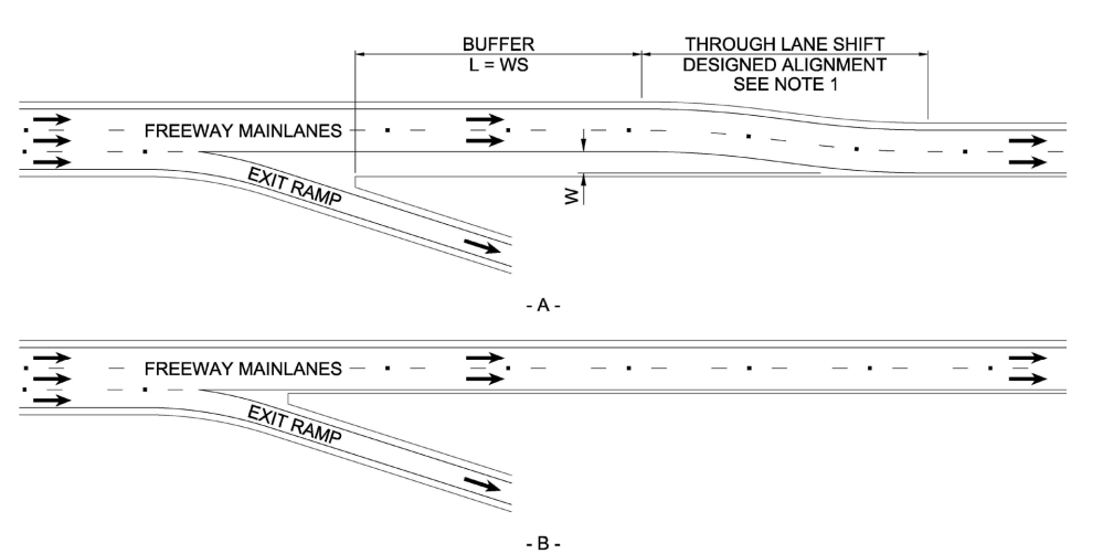
Notes:
- THE THROUGH LANE SHIFT SHOULD BE DESIGNE AS A HORIZONTAL ALIGNMENT IN ACCORDANCE WITH SECTION 4.7
- THIS IS NOT INTENDED TO SHOW STRIPPING OR PAVEMENT MARKING DETAILS.REFER TO THE TEXA MUTCD FOR ADDITIONAL INFORMATION.
- THIS FIGURE IS NOT INTENDED TO CONVEY LANE OR SHOULDER WIDTHS.REFER TO SECTION 8.1.7 AND 8.1.8 FOR LANE AND SHOULDER WIDTH INFORMATION.
- L = LENGTH OF BUFFERW = WIDTH OF OFFSET FOR THROUGH LANE SHIFTS= DESIGN SPEED
Figure 8-2 Preferred Left Through Lane Reduction Example
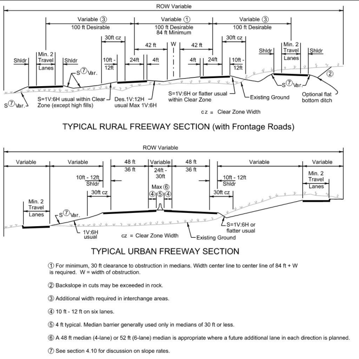
Figure 8-3 Typical Freeway Sections
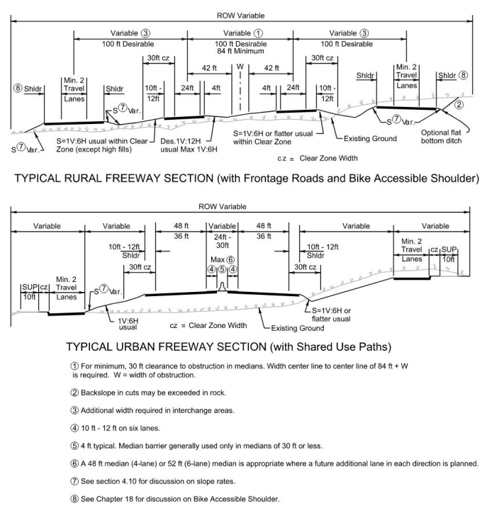
Figure 8-4 Alternative Typical Freeway Sections
8.1.7 Shoulders
Freeways must provide continuous surfaced shoulders on each side of the mainlane roadways for all applicable contexts as shown in
and
.
For four-lane freeways, the minimum shoulder widths must be 10-ft on the outside and 4-ft on the inside (median side).
On freeways of six lanes or more, 10-ft inside shoulders must be provided for emergency pulloffs. 10-ft outside shoulder should be provided along all speed change lanes, and 12-ft outside shoulders are recommended when designated as emergency evacuation lanes.
8.1.8 Speed Change Lanes
A speed change lane or auxiliary lane is defined as the portion of roadway adjoining the through lanes for speed change, turning, storage for turning, weaving, truck climbing and other purposes that supplement through-traffic movement (e.g., maintaining appropriate lane balance between ramp terminals). Auxiliary lanes are typically provided on freeways to:
- Comply with the concept of lane balance;
- Comply with capacity needs;
- Accommodate speed changes;
- Accommodate weaving;
- Maneuvering of entering and exiting traffic; and
- Simplify traffic operations by reducing the number of lane changes.
The width of an auxiliary lane should be equal to or greater than the adjacent through lane.
When auxiliary lanes are provided along freeway mainlanes, the shoulder width should be 10-ft. However a 6-ft shoulder can be considered in weaving areas of LOS A or LOS B. A design waiver is not required for this condition.
The length of a weaving auxiliary lane should be determined through the procedures outlined in the
which is applicable to all freeway contexts. See
or refer to
for additional guidance on the use of auxiliary lanes.
shows an example of a freeway auxiliary lane.
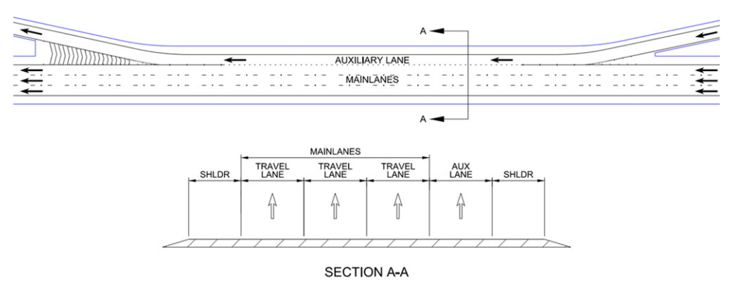
Figure 8-5 Example of Freeway Auxiliary Lane
8.1.9 Medians
The ultimate freeway section should be initially designed to reduce the adverse impact to highspeed and high-volume traffic resulting from construction in multiple phases when feasible. Several benefits can be realized from initially constructing the ultimate section such as:
- Lower levels of traffic handling and traffic shifts;
- Minimal temporary pavement and interim transitions;
- Construction and inflation cost savings; and
- Plans to accommodate future bridge columns and other appurtenances.
Under those circumstances where future additional lanes will be provided in the median area,
the usual median width of 24-ft should be increased by the appropriate multiple of 12-ft in anticipation of a future need for additional lanes.
Provisions should be made for any future need for managed lanes such as high occupancy vehicle lanes in the median.On freeways where median barrier is used, the horizontal alignment must be checked for adherence to the stopping sight distance criteria accounting for any restriction caused by the barrier. See
for additional information on median design for freeways.
See
for additional information on emergency freeway median crossings,
8.1.10 Curbs
In general,
curbs are not desirable along highspeed roadways.
They should not be used with high-speed through traffic lanes or ramp areas except at the outer edge of the shoulder where needed for drainage, in which case they must be traversable and should not be closer to the traveled way than the outer edge of the shoulder.8.1.11 Cross Slope and Superelevation
For guidance on Cross Slope and Superelevation, see
and
.
8.1.12 Grades
Guidance for maximum Grades for freeways is presented in
8.1.13 Roadside Design
Freeways must meet the minimum clear zone requirement shown in
.
Freeways in urban areas often have restrictive rights-of-way which may require fixed objects (e.g., overhead sign supports, bridge piers, retaining walls, high mast lighting, etc.) to be placed within the clear zone. Fixed objects located within the clear zone must be protected or deemed crashworthy by the Department. Where fixed objects are located beyond the clear zone, roadway side slopes must be either traversable or protected. See
for additional information on roadside design guidance.
8.1.14 Structures
Bridges, culverts, walls, tunnels, and other structures must be designed in accordance with the current
. The design loading must be HL-93 design live load unless design for a special vehicle is specified or warranted.
Structures that carry ramps must provide a clear width equal to the ramp width, including the ramp shoulders. The structure width and lateral clearance of highways and streets overpassing or underpassing the freeway are dependent on the functional class of the highway and street being underpassed or overpassed as discussed in
,
, and
.
Refer to the latest
and
for additional guidance on structures on TxDOT facilities.
8.1.15 Vertical Clearance
For guidance on Vertical Clearance, see
.
8.1.16 Ramps and Terminals
For guidance on Ramps and Terminals for all freeways, see
.
8.1.17 Outer Separations and Borders
The portion of the freeway between the mainlanes and frontage roads or ROW where frontage roads are not provided, should be wide enough to accommodate shoulders, auxiliary lanes, side slopes, drainage, retaining walls, ramps, signs, and other appurtenances necessary for traffic control.
Because of ROW limitations in urban areas, the outer separation may oftentimes be less than desired; however, in rural areas, where oncoming headlights along a two-way frontage road tend to reduce a driver’s comfort and perception on the freeway, the outer separation should be as wide as possible. Clear zones, as defined in
, are preferable for errant vehicle recovery and safety.
The outer separation should be as wide as economically feasible to provide a buffer zone between the freeway and its adjacent area. Where practical, the outer separation should extend beyond the construction limits when frontage roads are not provided.
The widths of the outer separation will typically range from 80 to 150-ft in rural areas.
Urban areas will typically provide lesser widths, especially when retaining walls are used.8.1.18 Frontage Roads
This subsection discusses frontage roads and includes information on the following topics:
- Function and uses;
- Planning;
- Capacity and level of service;
- Frontage road design criteria; and
- Conversion of frontage roads from two-way to one-way operation.
8.1.18.1 Function and Uses
Frontage roads separate local traffic from the higher speed freeway traffic and provide access to properties along the freeway corridor. Frontage roads serve numerous functions, depending on the context of the freeway they serve and the features of the surrounding area.
They may be used to control access to the freeway, function as a facility serving adjacent properties, and maintain circulation of traffic on each side of the freeway. They can also provide invaluable operational flexibility, serving as detour routes during mainlane crashes, mainlane maintenance activity, inclement weather, and for over-height loads and buses. Continuous frontage roads provide the operational flexibility required to manage saturation on freeways that include freeway surveillance and control.
In addition to these functions, frontage roads can prove advantageous when used as the first stage of construction for a future freeway facility. By constructing frontage roads prior to the mainlanes, interim traffic demands can often be satisfied, and a usable section of highway can be opened to the traveling public at a greatly reduced cost.
8.1.18.2 Planning
Frontage roads may be incorporated into a project at various points during project development, including the planning stage, subsequent to the planning stage, or after freeway construction. However, later incorporation of frontage roads will be more difficult.
A Frontage Road Briefing Document (FRBD)
must be developed, providing justification, and is approved by the District and then is submitted to Design Division prior to implementation of a new location frontage road (where no frontage road currently exists). An FRBD is also required when:- Converting an existing two-way frontage road to a one-way frontage road;
- There is major reconstruction or rehabilitation of existing two-way frontage roads and two-way operation is to remain (requires approval from Design Division); or
- A frontage road is being proposed to become two-way (any type of project).
Frontage road construction may be funded by TxDOT, a local government, or shared by both. The Texas Transportation Commission has adopted rules governing the construction and funding of frontage roads.
All frontage road development must be in accordance with the rules contained in
. Refer to the
for additional information.
Changes in control of access must be in accordance with
.
8.1.18.3 Capacity and Level of Service
Although techniques to estimate capacity and level of service on freeways and urban arterials are detailed in the
, these procedures should not be applied directly to frontage roads, as frontage roads have characteristic of both freeways (i.e., exit and entrance ramps) and urban arterials (i.e., driveways, cross streets, and signalized intersections).
The following report was developed to suggest techniques for estimating capacity and level of service on frontage roads:
- Kay Fitzpatrick, R. Lewis Nowlin, and Angelia H. Parham. . Texas Department of Transportation, Texas Transportation Institute, 1996.
Additional information can be found in TTI
, which contains procedures for the following:
- Determining Level of Service (LOS) on a continuous frontage road section;
- Analyzing frontage road weaving sections; and
- Determining spacing requirements for ramp junctions.
8.1.18.4 Frontage Road Design Criteria
Frontage roads are classified as collectors
and should be designed to match the values for a collector street or highway. See
for additional information.Any new frontage road
must be designed and constructed for one-way operation
unless prior approval from Design Division is obtained. There may be exceptions in certain isolated locations, where a one-way pattern would impose severe restrictions on circulation within an area. These exceptions must be approved by the Design Division during schematic design.8.1.18.5 Conversions of Frontage Roads from Two-Way to One-Way Operation
In some areas, existing frontage roads are operating as two-way facilities. Such two-way operation has the following disadvantages:
- Higher crash rates due to the risk of head-on collisions at the ramp terminals and driveways;
- Increased potential for wrong-way entry to the mainlanes;
- Complicated intersections requiring turning movements from/to the Exit Ramps onto/from the frontage road, crossing the opposite directions of travel;
- Increased signal phasing and sequencing requirements as compared to those normally available at signalized diamond interchanges; and
- Limited capacity when compared to one-way operations.
Existing two-way frontage roads should be converted to one-way operation when one or more of the following conditions exist:
- Queuing on the frontage road routinely backs up from an intersection to within 100-ft of a freeway entrance or exit ramp gore;
- The LOS of a signalized intersection on the frontage road drops below LOS C;
- Queuing in the counter-flow direction, which would not exist if the frontage road were one-way, routinely backs up from the stop line at a freeway entrance or exit ramp to within 100-ft of the intersection;
- Crash rates are above the statewide average crash rate for two-way frontage roads; or
- Major freeway reconstruction or rehabilitation is occurring in a developed or developing area.
Conversion of two-way frontage roads in urbanizing rural areas, with crossover interchanges spaced more than two miles apart, require consideration of additional crossover interchanges to minimize the distance traveled for adjacent residents and business patrons. Existing local street systems in the area should facilitate traffic circulation and minimize the travel time impact of converting frontage roads from two-way to one-way operation.
The conversion of two-way to one-way frontage roads should be accomplished with ramp and terminal design based on reconstruction criteria shown in
. For existing frontage road lanes may retain dimensions that meet minimum criteria, see
and
.
Two-way frontage roads should only be considered in rural areas where:
- The distances between crossover interchanges are relatively long (> two miles);
- The adjoining road system is typically discontinuous;
- The corridor is sparsely developed; and
- Development is not anticipated in the near future.
8.1.19 Collector-Distributor Roads
A collector-distributor (C-D) road is a road that parallels and connects the main travel lanes and frontage roads or entrance ramps. The purpose of a C-D road is to minimize weaving on the main travel lanes of a freeway by reducing the number of entrance and exit points on the through lanes while satisfying the demand for access to and from the freeway.
C-D roads are limited access roadways provided within a single interchange or continuously through two or more interchanges along a freeway corridor. They are similar to frontage roads except that access to abutting properties is not permitted.
The minimum lane arrangement for a C-D system is two C-D lanes and two mainlane through lanes, as shown in
; however, other combinations may be developed as capacity needs warrant.
Continuous C-D roads should be integrated to the main travel lane design to develop an overall system.
C-D roads should have shoulders equal to the width of the main travel lane shoulders.
Sometimes C-D roads are referred to as an “Intersection Bypass”. See
for an example of this application. In this case, a C-D road is similar to an exit ramp but is typically longer than a ramp. A C-D road is used to meet the following goals:
- Minimize weaving along the mainlanes and/or frontage roads;
- Optimize capacity and improve traffic operations at interchanges;
- Enhance safety by managing traffic speeds of the connected facilities;
- Minimize number of the mainlane ramps; and
- Enhance safety by providing a place for exiting traffic to wait to access cross streets, rather than backing up onto high-speed mainlanes.
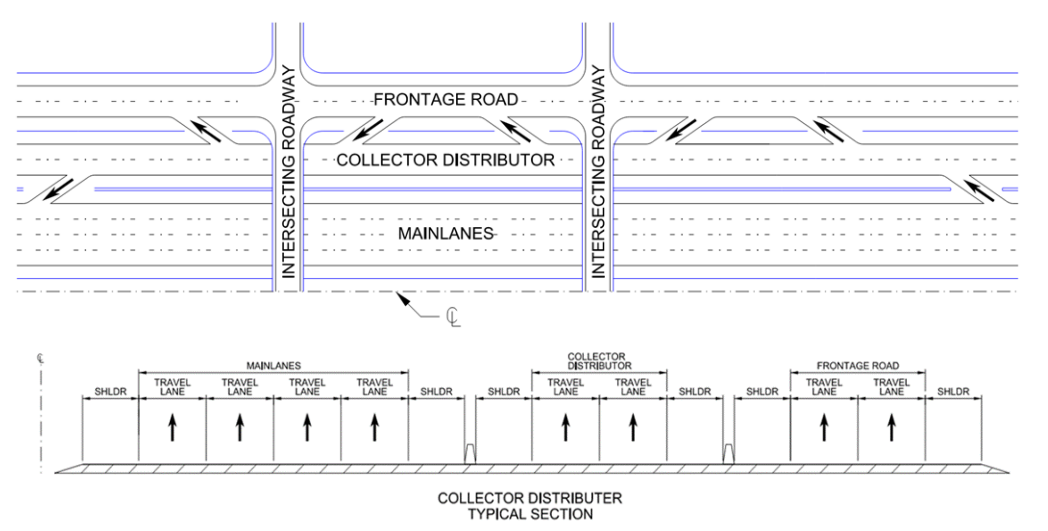
Figure 8-6 Example of a Collector-Distributor System
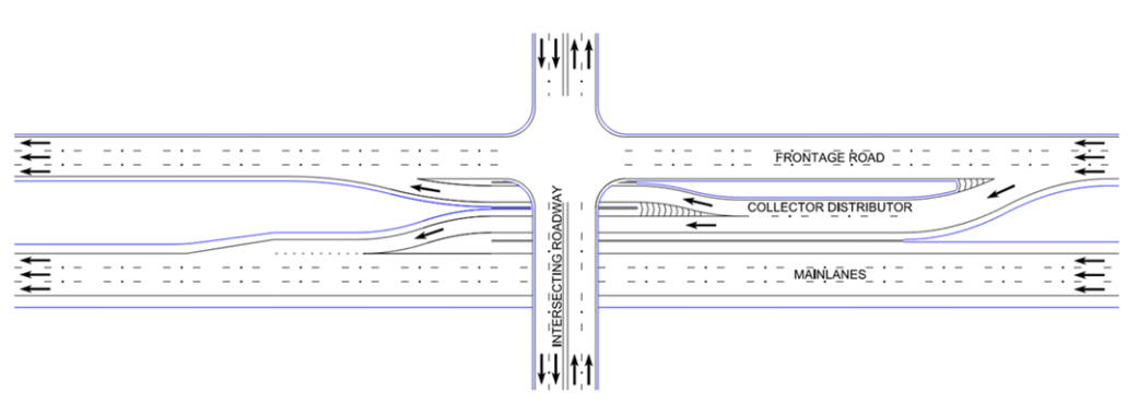
Figure 8-7 Example of an Intersection Bypass Collector-Distributor
C-D roads are a desirable component at all cloverleaf interchanges. Where there is considerable demand for frequent ingress and egress, as in and near the business districts of large cities, a collector-distributor road, continuous through several interchanges, should be provided. See
for an example of a cloverleaf interchange C-D road.
8.1.19.1 Collector-Distributor Design Criteria
The following design criteria should be used for the design of collector-distributor roads:
- Design Speed: No more than a 10 mph reduction from mainlane design speed;
- Lane Width: freeway mainlane width ( ); and
- Capacity analysis and basic lane determination should be performed for the overall system rather than for the separate roadways.
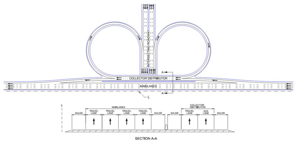
Figure 8-8 Example of a Cloverleaf Interchange Collector-Distributor
8.1.20 Crossing Facilities
The following references show the appropriate roadway widths for facilities crossing the freeway:
Freeways:
and
.
8.1.21 Access Control
This subsection discusses access control and includes the following topics:
- General Guidance;
- Control of Access Methods;
- Mainlane Access; and
- Frontage Road Access
8.1.21.1 General Guidance
The entire Interstate Highway System and portions of the State Highway System have been designated by the Texas Transportation Commission as Controlled Access Highways (refer to the
). It can be necessary to limit or deny an abutting owner’s access rights along certain sections of highways, which includes the right of ingress and egress and the right of direct access to and from the owner’s abutting property to the highway facility.
Such access may be controlled under the State’s Police Power (e.g., driveway permitting), which is an inherent right of sovereignty, which may entitle the owner to potential damages suffered by the loss of such access.
Refer to TxDOT’s
for additional information on the determination of control of access limits.
8.1.21.2 Control of Access Methods
A controlled access highway may be developed in either of two ways:
- Designation ( ); and
- Design (continuous frontage road and State’s police power). Refer to TxDOT’s for additional information.
8.1.21.2.1 Control of Access by Designation
When the Texas Transportation Commission designates a freeway as a controlled access facility under
, the State is empowered to control access through access restrictions. All Interstate Highways are designated as controlled access facilities as well as other routes that have been or may be designated by Commission Minute Order. These designated freeways may or may not have frontage roads, whichever arrangement is determined to be appropriate during Project Scoping. Development of freeways by designation, rather than solely by design, is the preferred design approach especially for all new location freeways.
8.1.21.2.2 Control of Access by Design
TxDOT is not empowered to purchase access rights. If an existing highway is to be developed as a controlled access facility solely by design (i.e., not designated by the Texas Transportation Commission), TxDOT must achieve access control by construction of continuous frontage roads and by the utilization of the State's Police Power to control driveways, particularly at ramp junctions with frontage roads. The State may effectively regulate driveway location in accordance with statewide policy as long as the following two conditions are met:
- Reasonable access is provided; and
- Land locking of an abutting property does not result.
Refer to TxDOT’s
for additional guidance on access requirements.
The design philosophy from the Frontage Roads Access section below applies whenever new or relocated ramps are to be provided along existing freeways. Access should be controlled at frontage road junctions through access restriction as illustrated in
and
.
Whenever access is to be controlled solely by provision of frontage roads, State’s Police Power to regulate driveway location and design should be used to control access near ramp junctions. However, where designation by the Transportation Commission is practical, use of access restrictions as illustrated in
and
is preferred over controlling access solely by design (State’s police power).
Some designated controlled access freeways may be a combination of new location and along an existing road.
,
, and State’s Police Powers may be used at appropriate locations.
8.1.21.3 Mainlane Access
Freeway mainlane access, either to or from abutting property or cross streets, is only allowed to occur through a ramp. This control of mainlane access may be achieved through one of the following methods:
- Through access restrictions whereby the access to the highway from abutting property owners is denied with ingress and egress to the mainlanes only at selected freeway or interchange ramps; or
- Through construction of frontage roads permitting access to the mainlanes only at selected ramps.
In either case, direct access from private property to the mainlanes is prohibited without exception.
8.1.21.4 Frontage Road Access
Information on the driveway clearances from the cross-street intersection is contained in TxDOT’s
and should be considered when locating driveways on projects involving the construction or reconstruction of ramps and/or frontage roads.
The remainder of this section addresses driveway and side street access in relation to ramps.
Frontage road access should be controlled by imposing recommended access restrictions in accordance with
and
whenever both of the following conditions prevail:
- ROW is being obtained from the abutting property owner(s); and
- A landlocked condition does not result;
Access may be controlled by use of the State's police power to control driveway location and design where either of the following conditions prevail:
- No ROW is obtained from the abutting property owner(s); or
- Restricting access results in landlocking an abutting property.
Whenever the State's Police Powers are used, the denial of access zone should be free of driveways insofar as practicable.
The placement of streets and driveways near freeway ramp junction with frontage road should be carefully considered and permitted only after local traffic operations are considered.
On reconstruction projects, it may be necessary to close or relocate driveways to meet these guidelines. If the closure/relocation is not feasible, and adjustment of the location of the ramp gore along the frontage road is not practical, then deviation from these recommended guidelines should be supported by a traffic operations and safety evaluation.
8.1.21.4.1 Access Beyond Exit Ramps
shows the recommended access control strategy for planned exit ramps and should be used where practical. This figure along with the accompanying values in
show the desirable spacing to be used between exit ramps and driveways, side streets, or cross streets if practical.
The number of weaving lanes is defined as the total number of lanes on the frontage road downstream from the ramp. Increased weaving, resulting in operational degradation, occurs when driveway or side street access on the frontage road is in close downstream proximity to exit ramp terminals. It is desirable but not required to maintain separation between the Intersection of Travel Lanes (see
and
) and downstream driveways or side streets.
It is recognized that there are occasions when meeting the exit ramp separation distance values in
may not be possible due to the nature of the existing development. In these cases, at least 250-ft of separation should be provided from the intersection of the exit ramp and frontage road travel lanes to the downstream driveway or side street.
Careful consideration should be given in situations like this, since the minimal separation distance may negatively impact the operation of the frontage road, exit ramp, driveway and/or side street traffic. When a minimum 250-ft separation distance cannot be obtained, consideration should be given to channelization methods, including curbed medians or other channelization that would restrict access to driveways within this 250-ft distance.
Refer to the
for channelization options.
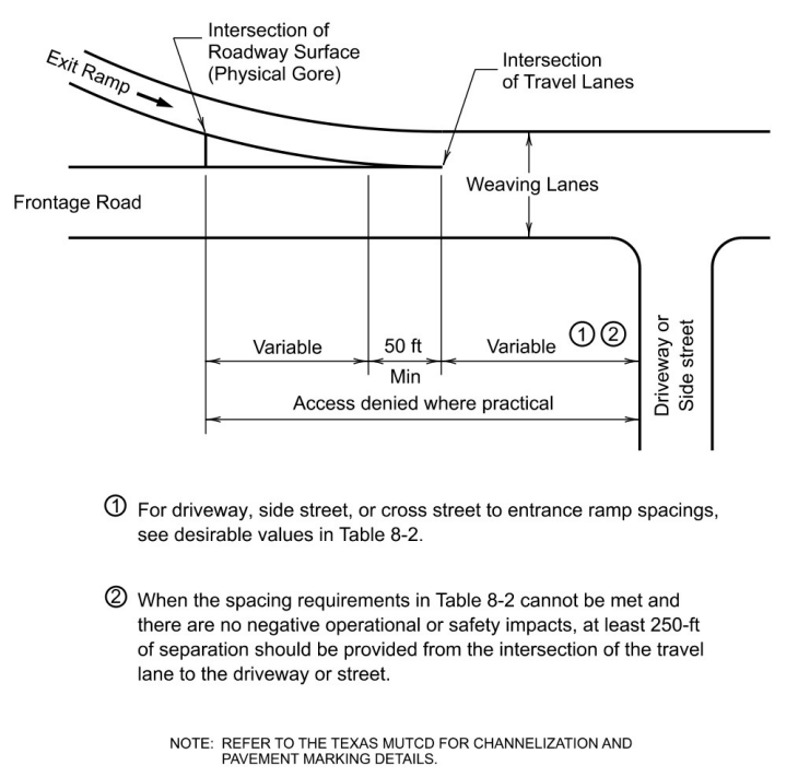
Figure 8-9 Recommended Access Control at Exit Ramp Junction with Frontage Road
Total Projected Frontage Road + Ramp Volume (vph) | Driveway or Side Street Projected Volume (vph) | Desirable Spacing (ft) | ||
Number of Weaving Lanes on Frontage Road | ||||
2 | 3 | 4 | ||
< 2500 | < 250 | 460 | 460 | 560 |
-- | > 250 | 520 | 460 | 560 |
-- | > 750 | 790 | 460 | 560 |
-- | >1000 | 1000 | 460 | 560 |
> 2500 | < 250 | 920 | 460 | 560 |
-- | > 250 | 950 | 460 | 560 |
-- | > 750 | 1000 | 600 | 690 |
-- | >1000 | 1000 | 1000 | 1000 |
8.1.21.4.2 Access Prior to Entrance Ramps
The presence of driveways or side streets in close upstream proximity to entrance ramp terminals, similar to exit ramps, increases weaving and results in operational degradation of the frontage roads. Therefore, maintaining proper separation is important.
shows the recommended access control strategy for planned entrance ramps and should be used where practical. There will be occasions when meeting the entrance ramp separation distance values shown in
may not be possible due to existing development conditions. In these cases, at least 100-ft of separation distance should be provided between the intersection of the entrance ramp and frontage road travel lanes and the upstream driveway or side street.
This limited separation negatively impacts the operation of the frontage road, entrance ramp, driveway, and/or side street traffic, therefore, careful consideration should be given to its use. When the 100-ft separation distance for entrance ramps cannot be obtained, consideration should be given to channelization methods that would restrict access to driveways within this 100-ft distance. Refer to the
for specific types of channelization.
8.1.21.4.3 Ramp Location
During schematic development, care should be exercised to develop the design in sufficient detail to accurately tie down the locations of ramp junctions with frontage roads and the location of access control limits. Refer to TxDOT’s
for specific guidance on schematic development.
These drawings are often displayed at meetings and hearings and become the basis for ROW instruments or the department’s regulation of driveway location for that project.
and
provide recommended access control at exit and entrance ramp junctions with frontage roads.
In some instances, ramps must be shifted to satisfy LOS considerations or geometric design controls. When this is necessary, the access control limits should also be shifted if ROW has not been previously purchased.
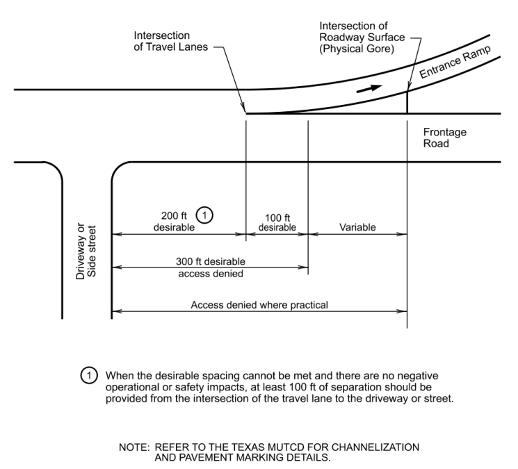
Figure 8-10 Recommended Access Control at Entrance Ramp Junction with Frontage Road.
8.1.21.4.4 Direct Access to a Ramp
The following requirements apply to direct access to a ramp from an adjacent property or street:
- All ramps with a frontage road:Direct access to a ramp is always prohibited for the full length of the ramp;
- Interstate freeway ramp without a frontage road or an Interstate interchange connector:Direct access is always prohibited under and for the full length of the ramp or Interstate interchange connector; and
- Non-Interstate facility without a frontage road, with or without access controlled by designation:Direct access is strongly discouraged. If allowed, the access location must be determined through the procedures and spacing criteria contained in this chapter and refer to TxDOT’s .
8.1.22 Managed Lanes and Toll Facilities
Managed lanes are defined by the FHWA as highway facilities or a set of lanes where operational strategies are proactively implemented and managed in response to changing conditions. This increases freeway efficiency, maximizes capacity, manages freeway demand, and generates revenue. Examples of managed lanes include high occupancy vehicle (HOV) lanes, value-priced lanes, high occupancy toll (HOT) lanes, and exclusive or special use lanes such as express lanes, bus lanes, transit lanes, and reversible flow lanes.
The following geometric design elements and related topics should be considered in the design of a managed lane facility:
- Geometric and operational consistency;
- Design speed;
- Cross sectional elements and alignment;
- Separation to general-purpose lanes;
- Access; and
- Drainage.
Refer to
or
for additional information on managed lane facilities.
A Design Exception would be required if the lane and shoulder widths shown in
are not met.
8.1.22.1 Geometric and Operational Consistency
The geometric design of managed lane and general-purpose facilities (i.e., freeway mainlanes) should be based on design principles and criteria for freeways. This reinforces driver expectations and promotes system connectivity.
Managed lanes are typically constructed as dedicated lanes within a freeway facility or in some cases, a freeway within a freeway. See
for an example typical section.
Managed lane design should match the design elements and traffic control devices on the adjacent freeway facility so that there is an established driver expectancy between both facilities. For example, if the adjacent freeway provides 50-mph ramps, a similar design should be applied to the ramps that connect the managed lanes and general-purpose lanes.
8.1.22.2 Design Speed
The design speed of a managed lane facility, including ramps and direct connectors, should match the design speed of the adjoining freeway facility.
This is especially true if there is a possibility of the managed lane facility being used by general-purpose traffic during the off-peak hours or at some time in the future. If there is no possibility that the facility will be used by general purpose traffic, and if use of this facility will be limited to a single vehicle type, such as buses, then the specific physical dimensions and operating characteristics of that vehicle should be considered in the design.
8.1.22.3 Cross-Sectional Elements and Alignment
8.1.22.3.1 Context Classification
Managed lane facilities must match the context classification of the adjoining freeway facility
8.1.22.3.2 Number of Lanes
Planning studies should be performed in conformance with a
analysis to confirm the number of through lanes needed for the managed lane system. This is particularly important when considering system-level demand inputs and outputs for a regional network of managed lanes.
The level of service for the managed lane facility must provide a greater level of service than the adjacent freeway facility.
8.1.22.3.3 Width of Lanes
The recommended and minimum lane width for a managed lane facility is 12-ft.
8.1.22.3.4 Width of Shoulders
For desirable and minimum shoulder widths refer to
Chapter 3.
8.1.22.3.5 Median
Medians on managed lane facilities should be designed in the same manner as freeway medians. For guidance on freeway Medians, see
.
8.1.22.3.6 Horizontal Alignment
For guidance on Horizontal Alignment, see
.
8.1.22.3.7 Vertical Alignment
For guidance on Vertical Alignment design, see
. Maximum grades for managed lane facilities must follow the requirements of freeways.
8.1.22.3.8 Cross Slope and Superelevation
For guidance on Cross Slope and Superelevation, see
and
.
8.1.22.3.9 Clear Zone
For Clear Zone requirements for managed lane facilities, see
for freeways.
8.1.22.3.10 Vertical Clearance
For guidance on Vertical Clearance, see
.
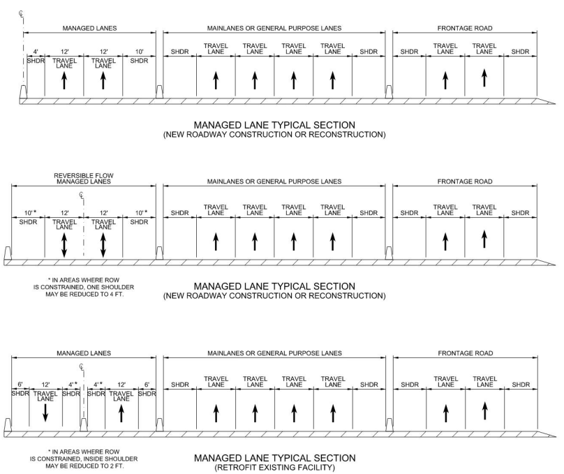
Figure 8-11 Example Managed Lane Typical Section
8.1.22.4 Separation to General Purpose Lanes
There are multiple ways to provide separation between managed lanes and the general-purpose lanes of a freeway. Barriers, buffers, flexible delineators, pavement markings, and separate facilities can all be used. In some cases, facilities may have a combination of separation types (e.g., a mixture of buffer separation and pavement marking separation where cross section is limited).
For additional information on separation methods for managed lane facilities, refer to
.
8.1.22.5 Access
Access to and from the managed lane facility must follow the ramp design guidance, see
.
In situations where weaving is required on the managed lane facility, the minimum ramp spacing must be determined with the analysis procedures outlined in the
. For early planning purposes, the applicable weaving distances on a freeway between two system interchanges, a system interchange and service interchange, or two service interchanges should be used.
Access to managed lane facilities can either be accomplished through a continuous access or limited access approach. The selection of access type is based on a general evaluation of the performance and management benefits for the entire freeway system as well as the costs of constructing and operating the managed lanes.
8.1.22.6 Drainage
Drainage criteria for managed lanes is identical to the drainage criteria of freeways. Refer to TxDOT’s
for drainage criteria requirements for freeways.
For managed lanes located to the left of general-purpose lanes, drainage is a particular consideration when the lanes are separated by a median barrier. In these scenarios, the shoulder width and inlet spacing must be designed to handle the required ponded width.
8.1.23 Tunnels
Development of highways and freeways may include sections constructed in tunnels to either carry the roadway under or through a natural obstacle or to minimize the effect of the roadway on the community. General conditions under which tunnel construction may be warranted include:
- Long, narrow terrain ridges where a cut section may either be more costly or carry environmental consequences;
- Narrow ROW where all of the surface area is needed for street purposes;
- Large intersection areas or a series of adjoining intersections on an irregular or diagonal street pattern;
- Grade-separated pedestrian and/or bicycle facilities are needed;
- Railroad yards, airport runways, or similar facilities;
- Parks or similar land uses (existing or planned); or
- Locations where ROW acquisition costs exceed cost of tunnel construction and operation.
Specific design parameters such as soil conditions, construction phasing, ventilation, drainage, lighting, pumping, and other mechanical or electrical components should be considered as a part of the design of highway tunnels. For further information on the design of tunnels, refer to
.