4.10.2 Speed Change Lanes
Speed Change Lanes are defined as acceleration or deceleration lanes for left or right turns, exit or entrance acceleration or deceleration lanes, or a climbing lane.
A design waiver is required for speed change lanes with lengths and widths that do not meet minimum criteria as presented in Appendix B.
Speed change lanes may be provided as space for deceleration/acceleration to/from intersecting side streets with significant volumes and high operating speeds. They also provide space for deceleration and optional storage of turning vehicles. The length of speed change lanes for turning vehicles consists of the following to components:
- Deceleration length; and
- Storage length.
Design Speed (mph) | Deceleration Length (ft) 2 Speed Differential 3 | Taper Length (ft) | Minimum 6,7 Storage Length (ft) | ||
None | 5-mph 4 | 10-mph 5 | |||
30 | 150 | 105 | 70 | 50 9 | 100 |
35 | 205 | 150 | 105 | 50 9 | |
40 | 265 | 205 | 150 | 50 9 | |
45 | 340 | 265 | 205 | 100 8 | |
50 | 415 | 340 | 265 | 100 8 | |
55 | 505 | 415 | 340 | 100 8 | |
60 | 600 | 505 | 415 | 100 8 | |
65 | 700 | 605 | 515 | 150 | |
70 | 815 | 720 | 630 | 150 | |
75 | 935 | 840 | 750 | 150 | |
80 | 1060 | 965 | 875 | 150 | |
Notes: | |||||
| |||||
4.10.2.1 Width of Speed Change Lanes
The preferable width of a speed change lane should match the through lane width of the facility. In constrained situations the speed change lane width may be reduced to 11- or 10-ft on arterial and collector facilities. A design waver will be required if a width of 10-ft is not met except on local roadways. Local roadways will require a design waiver if a width of 9-ft is not provided.
4.10.2.2 Left-Turn Deceleration Lanes
illustrates the use of left-turn lanes for all contexts. A short symmetrical reverse curve taper or straight taper may be used. For median left-turn lanes at intersections, a median divider width of 4-ft (measured to face of curb, if applicable) is recommended. Where pedestrian refuge is needed, a median divider width of 6-ft is required (measured minimum to face of curb, preferable to back of curb). If pedestrians are expected to cross the divider, then the divider should be a minimum of 5-ft wide (normal to direction of pedestrian travel) to accommodate a cut-through landing or refuge area that is at least 5-ft x 6-ft. For illustrations of these two cases, see
for additional guidance.
provides recommended taper lengths, deceleration lengths, and storage lengths for left-turn lanes. These guidelines may also be applied to the design of right-turn lanes.
For Rural roadways, adjustments to the deceleration length should be applied to a turn lane if the longitudinal grade exceeds 3 percent.
See
for adjustments factors due to steep longitudinal grades.4.10.2.2.1 Rural Left-Turn Lane Warrants
The additional expense of adding left-turn lanes on rural two-lane highways at intersecting crossroads is often not justified due to low volumes.
provides recommendations for when left-turn lanes should be considered for a typical rural two-lane highway intersection. Left-turn lanes may be added based recent crash data or projected volumes associated with planned development.
In instances on three-leg rural intersections where a left turn lane is not warranted due to low major roadway volume, but separation of through and turning traffic is still desired due to moderate to high left turn volume, a bypass lane can be installed. See
and
.
Example:
Three Leg Intersection
Left Turn Volume = 17 veh/hr
Major Road Volume = 150 veh/hr; 2 ln
Choose the next highest turn lane volume of 20 veh/h. The major road is 75 veh/h/ln, which is greater than 50, therefore a left turn lane is warranted.
Where used, left-turn lanes should be delineated with striping and pavement markers or jiggle bars. Passing should be restricted in advance of the intersection, and horizontal alignment shifts of the approaching travel lanes should be gradual.
shows typical geometry for a rural two-lane highway with left-turn bays at an intersecting crossroad.
Left-Turn Lane Peak-Hour Volume (veh/hr) | Three-Leg Intersection Major-Road Peak-Hour Volume (veh/hr/ln) for a Bypass Lane | Three-Leg Intersection Major-Road Peak-Hour Volume (veh/hr/ln) for a Left-Turn Lane | Four-Leg Intersection Major-Road Peak-Hour Volume (veh/hr/ln) for a Left-Turn Lane |
5 | 50 | 200 | 150 |
10 | 50 | 100 | 50 |
15 | < 50 | 100 | 50 |
20 or More | < 50 | 50 | < 50 |
Notes: | |||
| |||
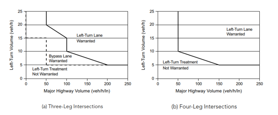
Figure 4-8: Suggested Left-Turn Warrants Based on Results from Benefit-Cost Evaluations for Intersections on Two-Lane Highways in Rural Areas
Source: AASHTO A Policy on Geometric Design of Highways and Streets
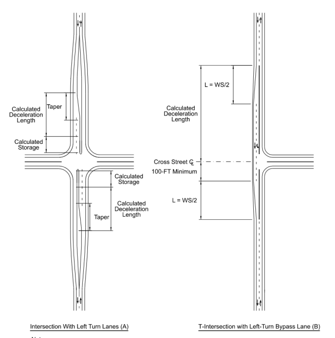
Notes:
- This is not intended to show striping or pavement marking details. refer to the Texas MUTCD for additional information.
- See Chapter 13, Intersections for additional design guidance on turn lanes.
- See Section 4.10.5 for additional design guidance on tapers.
- These figures are not intended to convey lane or shoulder widths. It is preferred to match the approach shoulder widths throughout a left-turn by-pass lane. If the shoulder width needs to be reduced for constrained situations, then it may be reduced to the minimum width for the appropriate functional classification shown in Appendix A.
Figure 4-9: Rural Two-Lane Highway with Left-Turn Bays at Intersecting Crossroad
Suggested guidelines and warrants for the installation of left-turn lanes on four-lane rural highways based on turning and through volumes is provided in
and
.
These volume-based guidelines indicate situations where a left-turn lane may be desirable, not necessarily situations where a left-turn lane is required.
Further discussion and examples of left-turn lane guidance can be found in
.Table 4-16: Guide for Left-Turn Lane Warrants for Four-Lane Highways in Rural Areas
Source: AASHTO A Policy on Geometric Design of Highways and Streets
Left-Turn Lane Peak-Hour Volume (veh/hr) | Three-Leg Intersection, Major Four-Lane Highway Peak-Hour Volume (veh/hr/ln) That Warrants a Left-Turn Lane | Four-Leg Intersection, Major Four-Lane Highway Peak-Hour Volume (veh/hr/ln) That Warrants a Left-Turn Lane |
5 | 75 | 50 |
10 | 75 | 25 |
15 | 50 | 25 |
20 | 50 | 25 |
25 | 50 | < 25 |
30 | 50 | < 25 |
35 | 50 | < 25 |
40 | 50 | < 25 |
45 | 50 | < 25 |
50 or More | 50 | < 25 |
Notes: | ||
| ||
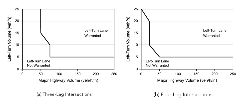
Figure 4-10: Suggested Left-Turn Warrants Based on Results from Benefit-Cost Evaluations for Rural Four-Lane Highways
Source: AASHTO A Policy on Geometric Design of Highways and Streets
4.10.2.2.2 Rural Town, Suburban, Urban, and Urban Core Left-Turn Lane Warrants
Suggested guidelines and warrants for the installation of left-turn lanes in urban and suburban areas based on turning and through volumes is provided in
and
.
These volume-based guidelines indicate situations where a left-turn lane may be desirable, not necessarily situations where a left-turn lane is required.
Further discussion and examples of left-turn lane guidance can be found in
.Table 4-17: Guide for Left-Turn Lane Warrants for Urban and Suburban Arterials
Source: AASHTO A Policy on Geometric Design of Highways and Streets
Left-Turn Lane Peak-Hour Volume (veh/hr) | Three-Leg Intersection, Major Four-Lane Highway Peak-Hour Volume (veh/hr/ln) That Warrants a Left-Turn Lane | Four-Leg Intersection, Major Four-Lane Highway Peak-Hour Volume (veh/hr/ln) That Warrants a Left-Turn Lane |
5 | 450 | 50 |
10 | 300 | 50 |
15 | 250 | 50 |
20 | 200 | 50 |
25 | 200 | 50 |
30 | 150 | 50 |
35 | 150 | 50 |
40 | 150 | 50 |
45 | 150 | < 50 |
50 or More | 100 | < 50 |
Notes: | ||
| ||
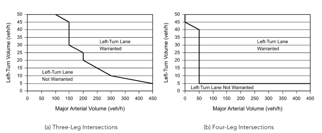
Figure 4-11: Suggested Left-Turn Warrants Based on Results from Benefit-Cost Evaluations for Intersections on Urban and Suburban Arterials
Source: AASHTO A Policy on Geometric Design of Highways and Streets
4.10.2.3 Acceleration Lanes
Acceleration lanes for right-turning or left-turning vehicles may be desirable for vehicles entering on multi-lane rural highways. Examples of both tapered and parallel accelerations lanes are shown in
. Recommended acceleration lengths are shown in
. Adjustments for grade are given in
.
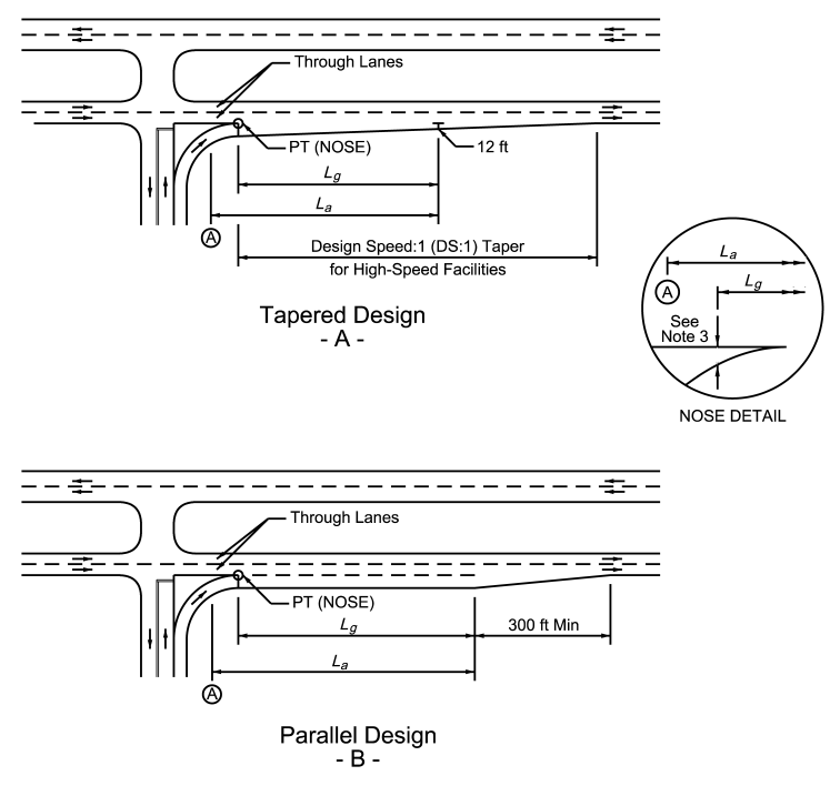
- Lais the recommended acceleration length as shown in Table 4-18 or as adjusted in Table 4-19.
- Point A is the feature that controls speed on the acceleration lane. Lashould not start back on the curvature of the ramp unless the radius equals 1,000-ft or more.
- Lgis the recommended gap acceptance length. Lgshould be a minimum of 300 to 500-ft depending on nose width. (Nose width 2’-10’)
- The value of Laor Lg, whichever produces the greater distance downstream from where the nose equals 2-ft, is suggested for use in the design of the acceleration lane distance.
Figure 4-12: Examples of Tapered and Parallel Acceleration Lanes
Design Speed of Controlling Feature on Ramp (mph) | |||||||||
Highway Design Speed (mph) | Stop Condition | 15 | 20 | 25 | 30 | 35 | 40 | 45 | 50 |
30 | 180 | 140 | - | - | - | - | - | - | - |
35 | 280 | 220 | 160 | - | - | - | - | - | - |
40 | 360 | 300 | 270 | 210 | 120 | - | - | - | - |
45 | 560 | 490 | 440 | 380 | 280 | 160 | - | - | - |
50 | 720 | 660 | 610 | 550 | 450 | 350 | 130 | - | - |
55 | 960 | 900 | 810 | 780 | 670 | 550 | 320 | 150 | - |
60 | 1200 | 1140 | 1100 | 1020 | 910 | 800 | 550 | 420 | 180 |
65 | 1410 | 1350 | 1310 | 1220 | 1120 | 1000 | 770 | 600 | 370 |
70 | 1620 | 1560 | 1520 | 1420 | 1350 | 1230 | 1000 | 820 | 580 |
75 | 1790 | 1730 | 1630 | 1580 | 1510 | 1420 | 1160 | 1040 | 780 |
80 | 2000 | 1900 | 1800 | 1750 | 1680 | 1600 | 1340 | 1240 | 980 |
Deceleration Lanes | ||||||||
Design Speed of Roadway (mph) | Ratio of Length on Grade to Length on Level 1 | |||||||
3 to 4% Upgrade | 3 to 4% Downgrade | 5 to 6% Upgrade | 5 to 6% Downgrade | |||||
All | 0.9 | 1.2 | 0.8 | 1.35 | ||||
Acceleration Lanes | ||||||||
Design Speed of Roadway (mph) | Ratio of Length on Grade to Length on Level 1 for Design Speed (mph) of Turning Roadway Curve | |||||||
20 | 25 | 30 | 35 | 40 | 45 | 50 | All Speeds | |
3 to 4% Upgrade | 3 to 4% Downgrade | |||||||
40 | 1.3 | 1.3 | 1.3 | 1.3 | - | - | - | 0.7 |
45 | 1.3 | 1.3 | 1.35 | 1.35 | - | - | - | 0.675 |
50 | 1.3 | 1.35 | 1.4 | 1.4 | 1.4 | - | - | 0.65 |
55 | 1.35 | 1.4 | 1.45 | 1.45 | 1.45 | 1.45 | - | 0.625 |
60 | 1.4 | 1.45 | 1.5 | 1.5 | 1.5 | 1.55 | 1.6 | 0.6 |
65 | 1.45 | 1.5 | 1.55 | 1.55 | 1.6 | 1.65 | 1.7 | 0.6 |
70 | 1.5 | 1.55 | 1.6 | 1.65 | 1.7 | 1.75 | 1.8 | 0.6 |
75 | 1.6 | 1.65 | 1.7 | 1.75 | 1.8 | 1.9 | 2.0 | 0.6 |
80 | 1.7 | 1.75 | 1.8 | 1.9 | 2.0 | 2.05 | 2.1 | 0.6 |
5 to 6% Upgrade | 5 to 6% Downgrade | |||||||
40 | 1.5 | 1.5 | 1.5 | 1.6 | - | - | - | 0.6 |
45 | 1.5 | 1.55 | 1.6 | 1.6 | - | - | - | 0.575 |
50 | 1.5 | 1.6 | 1.7 | 1.8 | 1.9 | 2.0 | - | 0.55 |
55 | 1.6 | 1.7 | 1.8 | 1.9 | 2.05 | 2.1 | - | 0.525 |
60 | 1.7 | 1.8 | 1.9 | 2.05 | 2.2 | 2.4 | 2.5 | 0.5 |
65 | 1.85 | 1.95 | 2.05 | 2.2 | 2.4 | 2.6 | 2.75 | 0.5 |
70 | 2.0 | 2.1 | 2.2 | 2.4 | 2.6 | 2.8 | 3.0 | 0.5 |
75 | 2.15 | 2.25 | 2.35 | 2.58 | 2.8 | 3.03 | 3.25 | 0.5 |
80 | 2.3 | 2.4 | 2.5 | 2.75 | 3.0 | 3.25 | 3.5 | 0.5 |
Notes: | ||||||||
| ||||||||
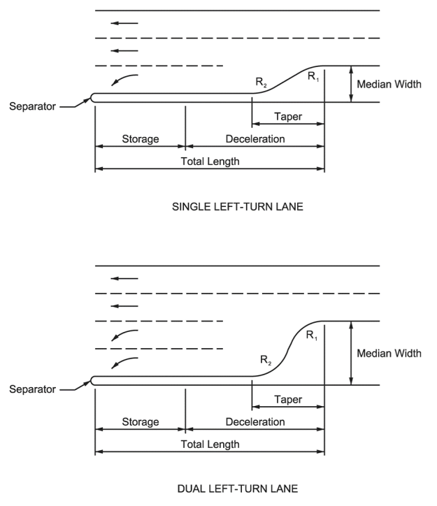
Figure 4-13: Left Turn Lane Examples (see
4.10.2.4 Deceleration Length
Deceleration length, with no speed differential, as shown in
assumes that deceleration starts at the beginning of the taper and continues to a stopped condition. Where providing this deceleration length is impractical, it may be acceptable to assume that turning vehicles will begin decelerating prior to arriving at the taper and clearing the through traffic lane. Using this assumption, see 5 mph and 10 mph speed differential columns in
for deceleration lengths.
4.10.2.5 Storage Length Calculations
The required storage may be obtained using an acceptable traffic model such as the latest version of the HCM software (HCS), SYNCHRO, or VISSIM or other acceptable simulation models. Where such model results have not been applied, the following formulas may be used:
Signalized:
Where:
L =
storage length, ft V =
left-turn volume per hour, vph Consider multiple turn lanes when V > 150. N =
number of cycles per hourRecommend between 20 and 25 cycles per hour for peak period operations if unknown.
2 =
a factor that provides for storage of all left-turning vehicles on most cyclesA value of 1.8 may be acceptable on collector streets.
S =
queue storage length, in feet, per vehicle% Trucks | S (ft) |
<5 | 25 |
5-9 | 30 |
10-14 | 35 |
15-19 | 40 |
Unsignalized:
Where:
L =
storage length, ft V =
left-turn volume per hour, vph 2 =
a factor that provides for storage of all left-turning vehicles on most cyclesA value of 1.8 may be acceptable on collector streets.
S =
queue storage length per vehicle, ft% Trucks | S (ft) |
<5 | 25 |
5-9 | 30 |
10-14 | 35 |
15-19 | 40 |
4.10.2.6 Dual Left-Turn Deceleration Lanes
For major signalized intersections where high peak hour left-turn volumes exceeding 150 vehicles per hour are expected, dual left-turn lanes should be considered. As with single left-turn lanes, dual left-turn lanes should include lengths for deceleration, storage, and taper.
provides recommended lengths for dual left-turn lanes.
4.10.2.7 Right-Turn Deceleration Lanes
illustrates a right-turn deceleration lane. The length of a single right-turn deceleration lane is the same as that for a single left-turn lane (
). However, the minimum queue storage is 30-ft for right-turn lanes.
The length for a dual right-turn lane is the same for a dual left-turn lane
(
). Refer to the
for guidelines as to when to consider a right-turn deceleration lane.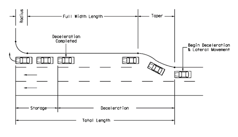
Figure 4-14: Lengths of Right Turn Deceleration Lanes
4.10.2.8 Right Turn Deceleration Lanes on Two-Lane Roadways
Shoulders 10-ft wide alongside the traffic lanes generally provide sufficient area for acceleration or deceleration of right-turning vehicles. Where the right turn deceleration or acceleration lane is being constructed adjacent to the through lanes, the minimum lane width is 10-ft with a 2-ft surfaced shoulder. Speed change lanes should be symmetrical along both sides of the highway to provide drivers with a balanced section. Refer to the
for guidelines as to when to consider a right-turn deceleration lane.
A deceleration-acceleration lane on one side of a two-lane highway, such as at a “tee” intersection, results in the appearance of a three-lane highway and may result in driver confusion. Therefore, right-turn speed change lanes are generally inappropriate for “tee” intersection design except where a four-lane section is provided. An example of this configuration is two through lanes (i.e., one through lane in each direction of traffic), one median left turn lane, and one right acceleration/deceleration lane. See
for length of deceleration lanes.
4.10.2.9 Right-Turn and U-Turn Acceleration Lanes
Acceleration lanes are generally not used on urban streets. Right-turn acceleration lanes may be appropriate on some rural highways such as high-volume highways where significant truck percentages are encountered. (see
).
provides acceleration distances and
for taper lengths if an acceleration lane is necessary. Right turn acceleration lanes that end must be yield controlled. This same concept also applies to turnaround lanes (see
).
4.10.2.10 Free Right-Turn Lanes
When an acceleration lane does not end, it is considered a free right turn lane. In these cases, stop or yield control may not be provided (see
).
Downstream access should be located so that there is adequate spacing for drivers to accelerate and weave lanes safely to access the connecting driveway or cross street. It is preferred to locate access points far enough downstream so that the acceleration distances shown in
and
are met plus the additional driveway spacing shown in the
. If this
preferred spacing cannot be met, the designer should consider a different type of right turn treatment, or the right turn lane should be yield controlled at the intersection.
A design waiver or design exception is not required if this spacing is not met. Refer to the
for driveway spacing requirements.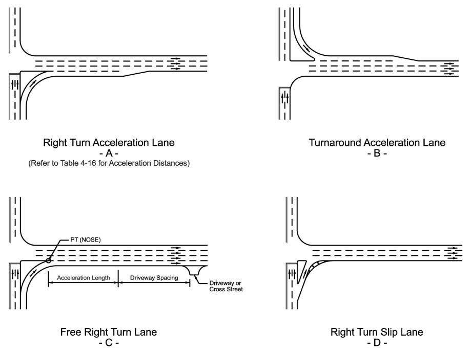
Notes:
- This is not intended to show striping or pavement marking details. Refer to the Texas MUTCD for information on striping and pavement marking details.
- Refer to Chapter 13 for additional information and guidance on Right Turn Slip Lanes. Figure A and C are not typically designed as right turn slip lanes, however there are several design elements discussed in Chapter 13 that may be incorporated for these types of right turn treatments (e.g. channelizing island, pedestrian considerations, etc.).
Figure 4-15: Types of Right Turn Treaments at Intersections
4.10.2.11 Dual-Right Turn Lanes
High volumes of right-turning vehicles may support a dual right-turn lane configuration to increase capacity for the turns while reducing delay for other movements at the intersection. Dual right-turn lanes can reduce both the length needed for the dual right-turn lanes and the corresponding green time needed for that movement. Dual right-turn movements may be in the form of either two exclusive right-turn lanes or one exclusive right-turn lane and a shared through-right-turn lane (see
).
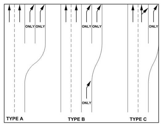
Figure 4-16: Types of Dual Right Turn Lanes
4.10.2.12 Climbing Lanes
It is desirable to provide an extra lane on the upgrade side of a two-lane highway as a climbing lane where the grade, traffic volume, and heavy vehicle volume combine to degrade traffic operations.
A climbing lane should be considered when one of the following three conditions exist:
- 10 mph or greater speed reduction is expected for a typical heavy vehicle;
- Level-of-service E or F exists on the upgrade; or
- A reduction of two or more levels of service is experienced when moving from the approach segment to the upgrade.
For low-volume roadways there is minimal delay, and a climbing lane may not be justified. For this reason, a climbing lane should only be considered on roadways with the following traffic conditions:
- Upgrade traffic flow rate is greater than 200 vehicles per hour; or
- Upgrade truck flow rate is greater than 20 vehicles per hour.
The upgrade flow rate is estimated by multiplying the anticipated or existing design hour volume by the directional distribution factor for the upgrade direction and dividing the result by the peak hour factor (see the
for definitions of these terms). To calculate the upgrade truck flow rate, multiply the upgrade flow rate by the percentage of trucks in the upgrade direction.
The beginning of a climbing lane should be introduced near the foot of the grade. The climbing lane should be preceded by a tapered section with a preferred taper ratio of 25:1 that should be at least 300-ft long
Attention should also be given to the location of the terminal point of the climbing lane. Ideally, the climbing lane should be extended to a point beyond the crest where a typical truck could reach a speed that is within 10 mph of the speed of other vehicles. In addition, climbing lanes should not end just prior to an obstruction such as a restrictive width bridge. The climbing lane should be followed by a tapered section with a ratio of 50:1.
For projects in new locations, or where an existing highway will be regraded, consider improving the grade line in lieu of providing a climbing lane. Refer to
for more information regarding the design of climbing lanes.
shows a typical section for climbing lanes on rural highways.
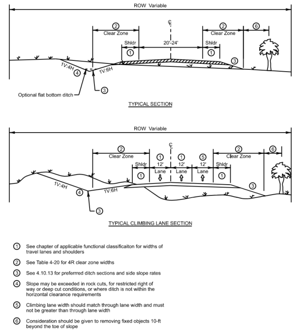
Figure 4-17: Climbing Lane Typical Section