17.3 Longitudinal Barriers
Traffic barriers are considered only when the obstacle is less forgiving than striking the barrier itself. Should a roadside obstacle exist, treatment should be considered in the following priority:
- Remove obstacle;
- Redesign the obstacle so it can be safely traversed;
- Relocate the obstacle to a point where it is less likely to be struck;
- Reduce impact severity by using an appropriate breakaway device;
- Shield the obstacle with a longitudinal traffic barrier designed for redirection or use a crash cushion; and
- Delineate the obstacle if the above alternatives are not appropriate.
17.3.1 Types of Barriers
17.3.1.1 Rigid
Common rigid barriers used by TxDOT are constant single-slope barriers and F-shape barriers that are cast in place or precast barriers anchored in accordance with TxDOT cast in place barrier standards. Concrete barriers placed in situ or keyed into the roadway pavement are considered rigid barriers. Concrete barriers are placed primarily where little movement of the barrier can be tolerated and typically do not deform when impacted. For concrete barriers that are anchored, between 0 and less than 1-ft of deflection is anticipated for a TL-3 (high-speed) pickup truck impact. Where considerable truck traffic exists (10% or greater) or is anticipated, a TL-4 rated barrier should be considered (minimum height of a TL-4 barrier is 36-inches). Concrete barriers are typically used in narrow medians to limit deflection and reduce the need for maintenance and repair. The exposed ends of the barrier need to be protected by an attenuator.
17.3.1.2 Semi-Rigid
Semi-rigid barriers commonly used by TxDOT include metal beam guard fence and both pinned and unanchored (a.k.a., freestanding) precast concrete barriers. Semi-rigid barriers have an expected deflection between 24 and 60 inches if impacted by a MASH TL-3 pickup truck under MASH test conditions. Metal beam guard fence is the most commonly used barrier by TxDOT. The current height tolerance for a new installation of a Midwest Guardrail System (MGS) is 31-inches plus or minus 1-inch measured from the road surface to the top of w-beam rail. Metal beam guard fence is used primarily to shield roadside obstacles, such as non-traversable slopes, utility poles, or trees. Precast concrete barriers can be used for temporary or permanent installations. Precast concrete barrier is most commonly used in work zones to shield personnel from traffic and motorists from work zone obstacles.
17.3.1.3 Flexible
High-tension cable barriers are the most commonly used flexible barriers. A cable barrier is sometimes referred to as a wire rope safety barrier. It consists of high-tension steel cables mounted on weak posts with a post foundation and anchor terminal. Cable barriers are used as median barriers to reduce median crossover vehicle encroachments.
Additional guidance for each barrier type is provided in subsequent sections.
17.3.1.4 Barrier Transitions
When transitioning from one type of barrier to another with significant differences in deflection or geometric shape it is necessary to provide a transition between the two barrier types to gradually increase stiffness to reduce the risk of pocketing and/or snagging. TxDOT has several standards for transitions from Semi-rigid (metal beam guard fence) to Rigid barriers available on the
webpage. The purpose of all these transitions is to gradually decrease the expected deflection to safely redirect an errant vehicle.
17.3.1.5 Special Barrier Applications
In the application of traffic control plans, situations may arise where transitions are needed from a rigid concrete barrier that has less anticipated deflection to barriers where more deflection is anticipated. The continuum for deflection from less deflection to greater deflection is cast-in-place, precast pinned, and precast non-pinned, respectively. Additionally, a temporary barrier run of 120-ft or less would generally be considered a short run and greater deflection would be anticipated. Refer to the
for additional guidance or contact the DES, Project Delivery Section – Roadway Standards and Research Group.
17.3.2 Applications
The three basic types of obstacles that are commonly shielded using roadside barriers are as follows:
- Slopes, lateral drop-offs, or terrain features;
- Bridge ends and the areas alongside bridges; and
- Other roadside obstacles that cannot be eliminated, made breakaway or otherwise traversable, or relocated.
: shows a summary of roadside features that are commonly shielded with guard fence. The abbreviation “cz” means within clear zone.
Roadside Feature | Applications |
Terrain Features: Steep Embankment Slope Rough Rock Cut Boulders Water Body (e.g., Ponds, Detention/Retention Ponds, Lakes, and Rivers/Streams) Lateral Drop-off (e.g., Borrow Pits) Side Ditches Quarries and Pits | cz1, See Figure 17-1 cz cz, diameter exceeds 6-in cz, depth exceeds 2-ft, permanent cz & steeper than 1V:1H and depth exceeds 2-ft cz & unsafe cross section2 see chapter 24 section 7 |
Bridges : Parapet Wall/Wingwall/Bridge Rail End Area Alongside Bridges | approaching traffic, or within cz of opposing traffic approaching traffic, or within cz of opposing traffic |
Roadside Obstacles: Trees Culvert Headwall 3 Wood Poles, Posts Bridge Piers, Abutments at Underpasses Retaining Walls, Noise Wall | cz & diameter exceeds 4-in cz & size of opening exceeds 3-ft (without safety grates only) cz & cross section/area exceeds 50 in 2 cz cz & not parallel to travel-way |
Notes: | |
1. cz – Within clear zone for highway class and traffic volume conditions. 2. For preferred ditch cross sections, see Section 4.12.7. 3. For specific 4R requirements see Section 4.10; for 3R see Section 10.3 | |
When evaluating roadside design, consideration should be given to the possible removal of metal beam guard fence if it is no longer needed.
Providing cross sections that make metal beam guard fence unnecessary is desirable.
This includes providing a sufficient clear zone recovery area and re-grading ditches to the extent possible in lieu of metal beam guard fence.Gateway Monuments are considered discretionary items (i.e., they are not necessary for the safety, maintenance, and operation of the roadway). Gateway Monuments, their foundations and any of their associated appurtenances proposed on the roadside of a facility must not be positioned within the clear recovery zone, and it is desirable that any monuments, their foundations and associated appurtenances be placed at least 10-ft beyond the clear zone. If this cannot be achieved, if a more desirable alternative location is not available, and if the monument must be placed within the clear zone, it must be shielded with an appropriate crashworthy device consistent with TxDOT Roadway Standards and applications. See
for additional information.
The combination of embankment height and side slope rate may indicate barrier protection consideration as shown in
. For low fill heights, a more abrupt slope rate is tolerable than at high fill heights.
Because steeper than 1V:4H side slopes provide little opportunity for drivers to redirect vehicles at high speeds, in the absence of guard fence, a 10-ft area free of obstructions should be provided by the designer beyond the toe of slope for slopes steeper than 1V:4H.
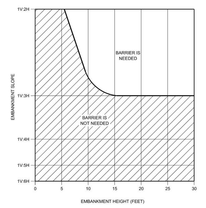
Figure 17-1: Guide for Use of Barrier for Embankment Heights and Slopes
17.3.3 Working Width
Working width is the distance between the traffic face of the barrier before the impact and the maximum lateral position of any major part of the system or vehicle during the impact (see
). Working width is related to deflection but working width considers the lateral position of the vehicle or any portion of the system. Working width should be considered when placing any longitudinal barrier. The Working height is the corresponding height at the maximum lateral position of any major part of the system or vehicle.
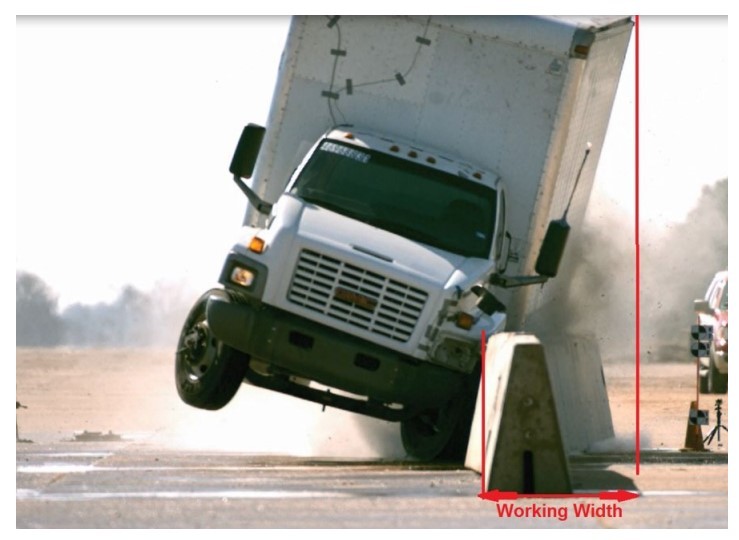
Figure 17-2: Working Width