15.7.3 Ramp Geometrics
15.7.3.1 Entrance Ramp Connections.
The horizontal geometry of entrance ramps will depend on the design speeds of the ramp, the connecting frontage road, and the connecting freeway. The departure from the frontage road should be a smooth transition appropriate for the design speed and speed classification (low speed/high speed) of the frontage road. The pavement elevation and cross slope of the departing ramp should match the pavement elevation and cross slope of the connecting frontage road up to the physical nose. Once the ramp is independent of the connecting frontage road, the ramp horizontal geometry and cross slope should be set to the design speed of the ramp. Where the ramp connects to the freeway, beyond the physical nose, the pavement elevation and cross slope of the entering ramp should match the pavement elevation and cross slope of the connecting freeway.
15.7.3.2 Exit Ramp Connections.
The horizontal geometry of the exit ramps will depend on the design speeds of the ramp, the connecting freeway, and the connecting frontage road. The departure from the freeway may be either tangent or parallel. The pavement elevation and cross slope of the departing ramp should match the pavement elevation and cross slope of the connecting freeway up to the physical nose. Once the ramp is independent of the connecting freeway, the ramp horizontal geometry and cross slope should be set to the design speed of the ramp. Where the ramp connects to the frontage road, beyond the physical nose, the pavement elevation and cross slope of the exiting ramp should match the pavement elevation and cross slope of the connecting frontage road.
15.7.3.3 Gores
The term “gore” indicates an area at the junction of entrance or exit ramps with the mainlane or frontage roads which is illustrated in
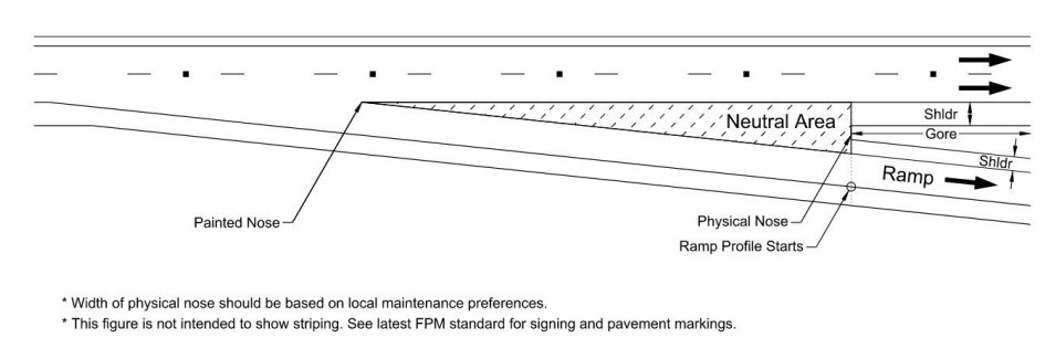
Figure 15-22: Typical Gore Area Characteristics
For an exit ramp junction at the mainlane, the physical nose is a point downstream from the painted nose of the gore, having some dimensional width that separates the roadways. The painted nose is a point, with no dimensional width, occurring where the travel ways intersect for the mainlane and ramp. The neutral area refers to the triangular area between the painted nose and physical nose.
The geometric layout of these is an important part of exit ramp terminal design. It is the decision point area that should be clearly seen and understood by approaching drivers and it should have a geometric shape appropriate for the likely speeds at that point. In a series of interchanges along a freeway, the gores should be uniform and have the same appearance to drivers.
The gore area, and the unpaved area beyond, should be kept as free of obstructions as practical to provide a clear recovery area. The unpaved area beyond the physical nose should be graded to be as nearly level with the roadways as practical so that vehicles inadvertently entering will not be overturned or abruptly stopped by steep slopes.
15.7.3.4 Grades and Profiles.
For design controls for crest and sag vertical curves on ramps and direct connectors, see
and
. Longer vertical curves with increased stopping sight distances should be provided wherever possible. See
for guidance on grade breaks without a vertical curve.
The tangent or controlling grade on ramps and direct connectors should be as flat as possible, and
preferably should be limited to 4 percent or less.
Maximum ramp grades are shown in
. In general, these grades should be used infrequently and only when necessary. Engineering judgement should be exercised when there are certain geometric constraints or topographic conditions that permit the use of these maximum grades.Ramp Design Speed (mph) | Max. Grade (%) |
25 to 30 | 7 |
35 to 40 | 6 |
Greater than or equal to 45 | 5 |
The ramp should have an independent profile from physical nose to physical nose. The profile grade within the neutral area should be designed as a projection of the connecting road profile and cross slope.
shows typical characteristics of ramp profile limits.
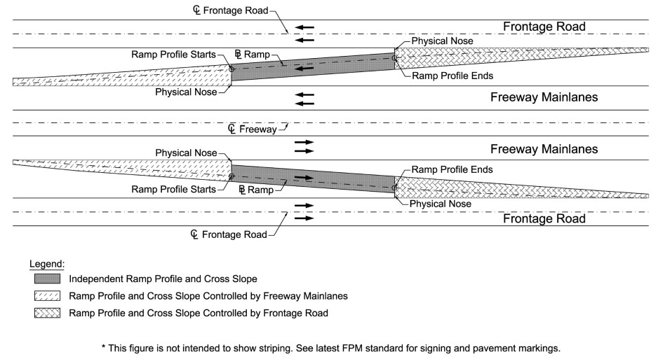
Figure 15-23: Typical Ramp Profile Characteristics
In some cases, it may be impractical to match the projected roadway profile and cross slope when designing the ramp proper profile. For these situations, a separated median area with mountable curb or barrier that warps the neutral area to join the projected profile of the connecting roadway and ramp proper may be considered. If a raised median is not preferred, surfaced mounted delineators may be used within the warped neutral area to discourage drivers from traversing this part of the ramp. See
for illustrations of a warped neutral area and
for maximum algebraic differences in cross slope.
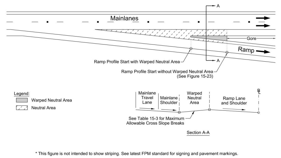
Figure 15-24: Warped Neutral Area
Design Speed of Exit or Entrance Curve (mph) | Maximum Algebraic Difference in Cross Slope at Crossover Line (%) |
Less than or equal to 20 | 5.0 to 8.0 |
25 to 30 | 5.0 to 6.0 |
Greater than or equal to 35 | 4.0 to 5.0 |