18.3 Elements of Design
18.3.1 Design Characteristics of Bicyclists
Regardless of the target design user identified in the bikeway selection process, the adult bicyclist should typically be used to establish geometric design controls because the adult bicyclist is typically the fastest and physically largest user. However, the designer should consider all likely users of a bikeway when establishing design controls. Common exemptions to using the adult bicyclist to establish design controls are:
- Using pedestrian performance criteria at street crossings where pedestrians will be crossing with bicyclists. This is common at shared use path, local street, or bicycle boulevard crossings of arterials, which must be designed to ensure a pedestrian can safely cross the road at a typical walking speed;
- Using the heights and speeds of recumbent bicyclists or child bicyclists for the purposes of establishing sight distances or crossing times at intersections. Both users are shorter in height and slower at starting from a stop compared to adult bicyclists; and
- Using a bicycle with a trailer for the purposes of designing median refuge islands, rail-crossings, or queuing areas because these devices lengthen and widen the operating space required.
18.3.2 Bicycles and Micromobility Devices
Some of the types of devices that are commonly used on Texas streets and trails are shown below in
. Typical variations in height, width, and length are noted. Although recommended widths for bike lanes, shared use paths, and sidewalks in the RDM generally address these devices, designers should be cognizant of the expected use of the longest and widest devices and provide appropriate accommodations for the use of these devices. See
for additional transit implications.
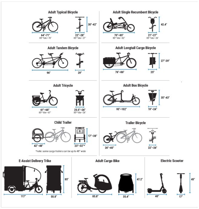
Figure 18-5: Typical Dimensions of Bicycle and Micromobility Types
18.3.3 Bicycling Operating Space
The physical space for each bicycle is determined by the width of the widest portion of the bicycle which is typically the handlebars or the wheelbase on adult tricycles, child trailers, or adult box bicycles. To accommodate most bicyclists, it is recommended that the target design user be an adult bicyclist operating with a trailer to establish the following minimum physical space dimensions:
- 30-in horizontal width;
- 10-ft length; and
- 7-ft height.
shows the operating space for the bicyclist described above. The minimum operating space for a bicyclist is 42-in. To provide additional shy space to other users or vertical objects, a minimum of 6-in of additional shy space is required. For this reason, operating space is generally assumed to be 48- in for a single direction of bicycle travel, and essentially functions as a “lane” of travel for a bicyclist as well as other Micromobility device users. This lane does not need to be marked on a bikeway unless it is operationally beneficial to do so. The bikeway width minimums provided in this guide account for the operating and shy spaces required for an adult bicyclist operating with a trailer.
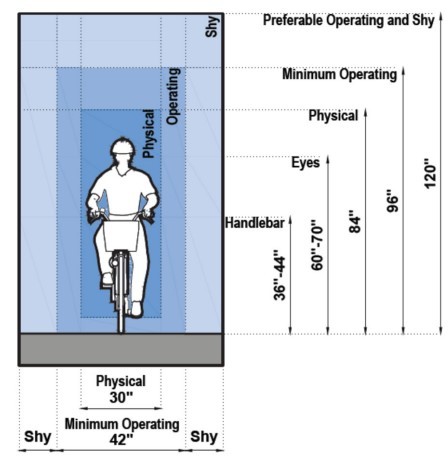
Figure 18-6: Operating Space for Bicyclists
18.3.4 Bicyclist Operating Speeds
The speed of a bicyclist is dependent upon several factors, including the age and physical condition of the user, the type and condition of the user’s equipment, the purpose and length of the trip, the condition, location, and grade of the bikeway, the prevailing wind speed and direction, and the number and types of other users on the facility. Although some adults may be able to maintain faster speeds (e.g., 25 to 30 mph) on level grades and attain speeds higher than 35 mph on steep descents, typical adult bicyclists average 8 to 12 mph on flat terrain, and steep inclines may result in speeds comparable to walking (2 to 3 mph). Research has found a median cruising speed for urban bicyclists as 9.7 mph with a 15th percentile speed of 8.2 mph. The 15th percentile speed should be used to inform bicycle crossing speeds at intersections as it represents the lowest range of bicyclist operating speeds.
For this reason, there is no single design speed that is recommended for all bikeways. Design speed considerations for bikeways are incorporated into specific bikeway guidance throughout
as appropriate.
18.3.5 Sight Distance
of the RDM provides detailed information about motorist Sight Distance. The
provides detailed guidance for evaluating bicyclist stopping sight distance, horizontal sight distance, and the evaluation of sight distance to establish traffic control at trail roadway intersections. The following supplements that guidance.
18.3.5.1 Bicycle Stopping Sight Distance
Adequate motor vehicle stopping sight distance is important for the safety of pedestrians and bicyclists who must cross roadways. See
for procedures for determining motor vehicle stopping sight distances.
Bicycle stopping sight distance (SSD) is the distance needed to bring a bicycle to a fully controlled stop. It is a function of the user’s perception and brake reaction time, the initial speed, the coefficient of friction between the wheels and the pavement, the braking ability of the user’s equipment, and the grade. The coefficient of friction for the typical skidding bicyclist is 0.32 for dry conditions and 0.16 for wet conditions. A perception and brake reaction time of 2.5 seconds should often be used, though 1.5 seconds may be used where braking or stopping is more expected, such when approaching intersections where scanning for conflicts is anticipated. Stopping sight distance can also be calculated using the formula shown in
. The table in
shows the minimum stopping sight distance for a typical adult bicyclist under wet conditions at various design speeds and grades based on a total perception and brake reaction time of 2.5 seconds
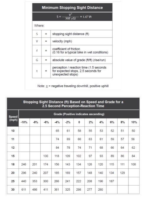
Figure 18-7: Stopping Sight Distance Formula and Table
18.3.5.2 Intersection Sight Distance
establishes a range of recommended sight triangles that correspond to requirements for motorists to have sufficient space to identify, react, and potentially yield to other traffic at an intersection based on the traffic control applied at the intersection.
Applying the sight triangle requirements provided in
will generally result in sufficient sight distance for bicyclists when operating on bicycle facilities located within the street, such as shared lanes, bike lanes, and separated bike lanes. Sight triangles should remain clear between 2.3-ft and 7-ft measured above the ground surface to account for the wide range of bicyclist eye heights and recumbent bicyclists as well as to ensure the visibility of child bicyclists to approaching motorists.
Intersections of Shared Use Paths and Roadways should be calculated using a combination of Motorists SSD requirements along their travel path and bicyclist SSD along their travel path. The
provides additional discussion on these sight triangles considerations.
18.3.5.3 Sight Distance Considerations at Intersections with Separated Bike Lanes and Sidepaths
At intersections with separated bike lanes and sidepaths it is important to evaluate potential right and left turning conflicts across the bikeway with right turning motorists (Case A) and left turning motorists (Case B), both of which create two unique sight triangles. For each case, there are two yielding scenarios based on who is closest to the intersection for which the provision of adequate sight distance between users is paramount.
18.3.5.3.1 Turning Motorist Yields to (or Stops For) Through Bicyclists
This scenario occurs when a through moving bicyclist arrives or will arrive at the crossing prior to a turning motorist, who must stop or yield to the bicyclist who is likely to be within the intersection at the time the motorist turns. This is shown visually in the top portion of
. Vertical elements near the intersection to separate bicyclists, including on-street parking, should be set back sufficiently for the motorist to see the approaching bicyclist providing the motorist sufficient time to slow or stop before the conflict point.
18.3.5.3.2 Through Bicyclist Yields to (or Stops For) Turning Motorist
This scenario occurs when a turning motorist arrives or will arrive at the crossing prior to a through moving bicyclist. This is shown visually in the bottom portion of
. This scenario can occur when a bicyclist approaches after a motorist has stopped and yielded to other people crossing in the intersection and the crossing is clear for the motorist to proceed. The motorist may begin turning as the bicyclist approaches, requiring the bicyclist to slow and potentially stop while the motorist completes the turning movement.
To provide sufficient sight distance between turning motorists and approaching bicyclist, it is necessary to provide a minimum approach clear space. This clear space is calculated by the determining the amount of space traveled by each user navigating the approach before they reach the conflict point which occurs in each of these zones:
- Recognition zone– the approaching bicyclist, motorist, or pedestrian has an opportunity to see the other user(s) and evaluate their respective approach speeds;
- Decision zone– the bicyclist, motorist, or pedestrian identifies who is likely to arrive at the intersection first and adjusts their speed to yield or stop if necessary; and
- Yield/stop zone– a space for the motorist or bicyclist to yield or stop, if necessary
The key design parameter to determine the necessary approach clear space is the turning speed of the approaching motorist which is influenced strongly by the effective turning radius available to them to execute the turn. It is preferable for turning motorist speeds to be below 15 mph at locations where they are expected to stop or yield to pedestrians and bicyclists in a crossing.
presents approach clear space values assuming the bicyclist design speed is 15 mph and that stopping is occurring under wet conditions and on flat terrain. As both bicyclists and motorists should be expecting potential conflict or the need to stop or yield, reaction times are assumed to be 1.5 seconds. The approach clear space may be increased or decreased to account for other approach speeds or reaction times if they are known. The values for clear space in
are measured back from the point of curvature of the motorist’s effective turning radius (i.e., fastest path), which represents the location where the motorist will have decelerated to the turning speed. This location may or may not be the curb line point of curvature.
Effective Vehicle Turning Radius | Vehicular Turning Speed | Approach Clear Spa |
<18 ft | <10 mph* | 20 ft |
18 ft | 10 mph | 40 ft |
25 ft | 15 mph | 50 ft |
30 ft | 20 mph | 60 ft |
≥50 ft | 25 mph | 70 ft |
*Most low volume driveways and alleys
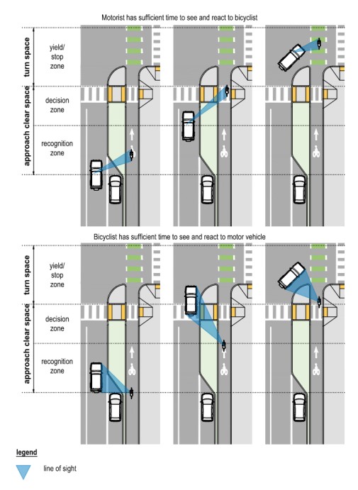
Figure 18-8: Yielding Scenarios Case A
(Refer to the
and
for additional signing and pavement marking guidance.)
18.3.5.3.3 Case A: Right-Turning Motorist Across Separated Bike Lane or Sidepath
depicts Case A, which applies when a motorist is making a permissive right turn across a bikeway. In this case the motorist will be decelerating for the right turn and their turning speed will be controlled by the intersection corner geometry and width of the receiving roadway.
identifies the minimum approach clear space, measured from the point of curvature of the motorist’s effective turning radius, which represents the location where the motorist will have decelerated to the turning speed. This location may or may not be the curb line point of curvature. Providing the appropriate clear space provides the necessary sight lines between motorists and bicyclists to stop (or yield) as appropriate. For locations with two-way separated bike lanes or sidepaths, additional approach clear space is not typically required as the recognition zone between the counter-flow bicyclist movement and the right-turning motorists should exceed the recommended sight distances.
18.3.5.3.4 Case B: Left-Turning Motorist Across Separated Bike Lane or Sidepath
depicts Case B, which applies when a motorist is making a permissive left turn across a bikeway. On two-way streets with a two-way separated bike lane or sidepath, there are two sight lines that should be maintained. A left-turning motorist approaching a turn needs a line of sight to bicyclists approaching from the same direction.
identifies the minimum approach clear space based on the effective turning radius for the left-turning motorist.
The provision of Bike Case A for motorists making a right-turn across a two-way bikeway provide the necessary line of sight between a left-turning motorist and a bicyclist approaching from the opposite direction. On one-way streets with a left-side separated bike lane or sidepath, Case A should be applied for left turns as it has the same operational dynamics
On streets with two-way traffic flow, the operational dynamic of a motorist looking for gaps in traffic creates unique challenges that cannot be resolved through improving sight distance. This is a challenging maneuver because the motorist is primarily looking for gaps in oncoming motor vehicle traffic and is less likely to scan for bicyclists approaching from behind. Unlike for Case A where the motorist is decelerating towards the crossing, the motorist in Case B will be accelerating towards the crossing once they perceive a gap in traffic. This creates a higher potential for conflicts on roads with the following conditions present:
- High traffic volumes and multiple approach lanes;
- Higher operating speeds; and
- High left turn volumes.
- High volumes of right-turn-on-red motorists from the intersecting side street, where turning motorists:
- may not be scanning for bicyclists or pedestrians approaching from the right; or
- block the crosswalk requiring bicyclists and pedestrians to cross behind them limiting their visibility to left-turning motorists from the main roadway.
Where it is not feasible to eliminate high-speed and high-volume conflicts through signalization or other traffic control, it may be necessary to reevaluate whether turns should be permitted, whether a sidepath or two-way separated bike lane is appropriate at the location, to provide adequate space for the motorist to complete the turn and then stop or yield to potential conflicts with crossing bicyclists and pedestrians with a protected intersection configuration (see
).
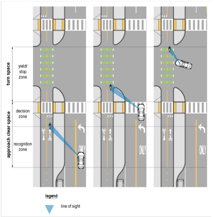
Figure 18-9: Intersection Sight Distance Case B
(Refer to the
and
for additional signing and pavement marking guidance.)
18.3.6 Horizontal Shifting Tapers
Changing the horizontal alignment of bike lanes and separated bike lanes may be accomplished with either horizontal curves or shifting tapers. Large radius curves which meet or exceed the guidance for horizontal curves of shared use paths may be used but will typically only be practical for use on shared use paths. In most applications within a roadway corridor, tapers will be easier to establish and are sufficient. Tapers should generally occur gradually, with a minimum length as calculated using the formula in
.
Table 18-4: Shifting Taper Equation
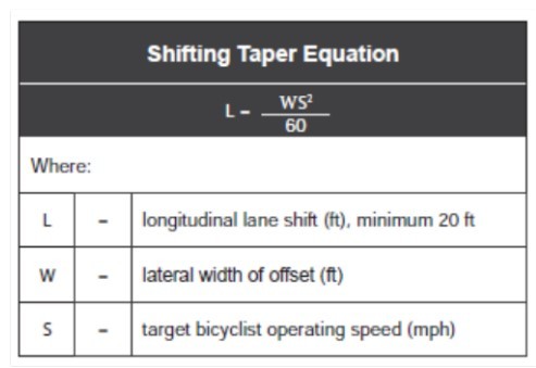
Solid white lane lines should be used to guide bicyclists around obstructions at a taper of Length (L) = (1+ W (Width of Obstruction)) * Bicyclist Speed (S) along the roadway (e.g., drainage grates) or shared use paths (e.g., bollards) following the
Section 9C.06 and Figure 9C-8. See guidance on design speed for each bikeway type throughout
18.3.7 Surface Considerations
18.3.7.1 Paved Surfaces
It is important to construct and maintain a smooth ridable surface clear of defects, joints, and other potential obstructions on bicycle facilities. Shared use paths must also meet pedestrian accessibility surface requirements. Reinforced concrete is typically preferred for all bikeways compared with asphalt, crushed aggregate, sand, clay, or stabilized earth. Since unpaved surfaces provide less traction, they decrease braking ability for bicyclists which can cause bicyclists to lose control more easily. Past research has shown that smoother surfaces are desirable for bicyclists. When placing a seal coat as a final driving surface, consider one of the following low cost options to provide an improved riding surface for bicycles: use a smaller seal coat aggregate, use a smaller seal coat aggregate on the shoulders, use fog seal on existing seal coated shoulders rather than a new seal coat, or use smaller aggregate for the top course of multiple course seal coats.
18.3.7.2 Permeable Pavements
If permeable pavements are smooth, stable, and slip resistant, they can be used for bikeways. By facilitating gradual absorption of water into the ground, permeable pavement can increase bike traction and reduce icing by providing an outlet for standing water, provided that the surface is maintained to ensure continued permeability.
Locating utilities within or close to permeable pavements should be avoided to the maximum extent possible or limited to crossings of the bikeway. When repairs are necessary, utility companies sometimes do not recognize permeable pavements, and replace them with standard asphalt, reducing stormwater treatment capacity. Where crossings are unavoidable, a carrier pipe should be provided to allow access to the utility without damaging the permeable pavement.
18.3.7.3 Unpaved Surfaces
Unpaved surfaces may be appropriate on an interim basis, but the preferred trail surface is paved. Interim unpaved surfaces could be used on rural shared use paths in relatively flat terrain, where the intended use of the path is primarily recreational. To accommodate people with disabilities, unpaved pathways should be constructed of materials that are firm and stable. Possible surfaces for unpaved paths include crushed stone, stabilized earth, and limestone screenings, depending upon local availability.
18.3.8 Utility Considerations
Addressing utility location may not be practical in retrofit situations where minimal reconstruction is anticipated. In those cases, care should be taken to ensure utilities will not present a hazard to bicyclists.
In new construction or substantial reconstruction presents opportunities to proactively address utility placement. Careful consideration of utilities within a roadway corridor can minimize potential utility conflicts with bicyclists and ensure adequate maintenance access for utility owners. The following should be considered:
- Avoid locating utility covers and large ventilation grates within bikeways to maintain a smooth bicycling surface and minimize detours during utility work. Where unavoidable, utility covers and large ventilation grates within bikeways should be:
- Smooth and flush with the bikeways surface;
- Minimizes the need for avoidance maneuvers by bicyclists; and
- Skid resistant to prevent a crash hazard.
- Locate poles and fire hydrants outside a minimum of 2-ft from bikeways.
- Bikeways retrofitted within an existing roadway may require realignment of traffic signal heads and detection equipment.
- Where bikeways are collocated with overhead lines, designers should be aware of required clearances from both poles and overhead conductors, and ensure that site elements such as bridges, railings, retaining walls, signs, and bicyclists’ operating envelope remain outside of the required clearances.
18.3.9 Drainage Considerations
Bikeways should be designed to prevent water ponding, ice formation, and the collection of debris. The following should be considered:
- A cross slope of 1 percent typically provides adequate conveyance of drainage;
- Sloping bikeways in one direction instead of crowning is preferred and simplifies drainage and surface construction;
- Bikeways retrofitted within a road corridor may be located within existing slope and drainage patterns of the respective roadway to minimize changes to the roadway’s drainage system;
- Drainage grates should be located outside the bikeway whenever practical (e.g., placed entirely within a gutter next to a bike lane) to minimize a reduction of the usable width of the bikeway; and
- Drainage grates that extend into a bikeway may cause bicyclists to swerve increasing crash risks. Where this is unavoidable, to minimize crash risk the following should be considered;
- Guide bicyclists around the grate with pavement markings (see and refer to the ); and
- Install bicycle friendly drainage grates which meet the following parameters:
- Skid resistant to prevent a crash hazard;
- Align grate openings perpendicular to the bicyclists’ direction of travel (see );
- Limit the gap between the grate and frame to 0.5 inch or less, perpendicular to the path of travel; and
- Grates should remain smooth and flush with the bikeways surface.
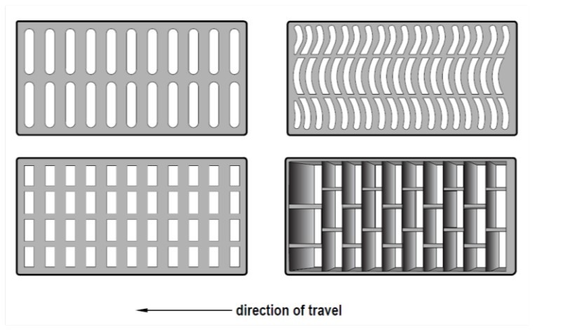
Figure 18-10 : Bike Compatible Drainage Grates
18.3.10 Bikeway Curb Considerations
Some curb types can increase the risk of bicycle crashes if struck by a wheel or pedal. The face of curb angle and curb height influence the functional width of the bikeway, crash risk to bicyclists, the ability to exit bikeways, and the risk of encroachment into the bikeway by other users. In locations where the bikeway is located between curbs, it is preferable to provide sloping curbs or reduced height curbs (less than 3-in). For curbs less than 3-in in height there is no minimum shy space; however, shy space to other appurtenances should be carefully considered. For curbs between 3-in and less than 6-in in height, a desirable shy space of 1-ft, with no minimum in constrained conditions, applies. Refer to the current
for illustrations on the various TxDOT standard curb types.
Curbs with integral gutters include a longitudinal seam parallel to bicycle travel that may deteriorate, resulting in dips or ridges that increase crash risk for bicyclists. Gutters also may have uneven surfaces where street resurfacing activities do not adequately remove asphalt approaching the gutter. Where curbs are provided with integral gutter, the minimum shy space to the curb is the width of the gutter.
18.3.11 Railings and Barriers Adjacent to Bikeways
A barrier that separates vehicular traffic from a sidepath or separated bike lane must:
- Meet the current barrier standards for the vehicular speed; and
- Provide an end treatment consistent with current Roadway Design Standard practice.
Where barriers are used immediately adjacent to a sidepath with minimum width dimensions, there may be risk a bicyclist could fall over the top. In these circumstances a minimum barrier height of 42-in is required. Barriers across bridge structures must meet the respective TxDOT’s Bridge Railing Manual requirements. Where barriers are used immediately adjacent to a sidepath with minimum width dimensions, there may be risk a bicyclist could fall over the top. In these circumstances a minimum barrier height of 42-in is required. Barriers across bridge structures must meet the respective TxDOT’s
requirements.
Barriers or railings located on the outside of a sidepath used to protect bicyclists and path users from falling into a hazard must be a minimum of 42-in in height. A higher 48-in to 54-in continuous barrier or railing may be considered in locations where:
- Bicyclist speeds are likely to be high (such as on a downgrade);
- High winds are typical (such as on bridges); or
- A bicyclist could impact a railing at a 25- degree angle or greater (such as on a curve).
Shy spaces to railings and barriers shall not be included within the width of the shared use path (SUP) or other bikeways. (see
).
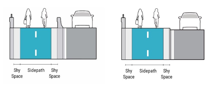
Figure 18-11: Example Bridge with Barriers for Sidepaths; High-speed (left) and Low-speed (right)
Where shared use sidepaths or separated bike lanes with sidewalks are provided on a bridge where the roadway cross section must narrow, the narrowing should be prioritized in the following order:
- Minimize shy distances to constrained conditions to vertical barriers (1-ft);
- Minimize street buffer to minimum width (4-ft);
- Narrow sidepath width from desired to constrained minimum;
- Narrow separated bike lane width from desired to minimum; or
- Narrow sidewalk width to the minimum.
18.3.12 Intersection Elements
18.3.12.1 Bicycle Crossing / Conflict Markings
Where a bike lane crosses an intersection separate from a crosswalk, bike lane markings may be extended through the intersection to delineate the bicycle crossing. Bike lane crossings are desirable to:
- Delineate a preferred path for people bicycling through the intersection, especially a crossing of a wide or complex intersection;
- Improve the visibility and recognizability of the bike crossing to roadway users; and
- Encourage motorist stop or yielding behavior, where motorists must merge or turn across the path of a bicyclist or pedestrian
provides design details for various bike crossing scenarios.
Where marking the conflict area is desirable, a dotted white edge line should be used to delineate the bicycle lane extension through the intersection by marking the left and right edge of the bicycle lane. The dotted lines are 2- ft in length with 2-ft to 6-ft gaps located on the edge of the bike lane. Normal width (6-in) or wide lane line widths (8-in) may be used, but they should typically match the width of the bike lane lines. Conflict area visibility may be enhanced with green-colored pavement and a bicycle lane symbol. If used, green-colored pavement should generally match the pattern of the dotted edge lines but may be solid where additional emphasis of the crossing is desired (see
for conditions of allowed use of green-colored pavement marking).
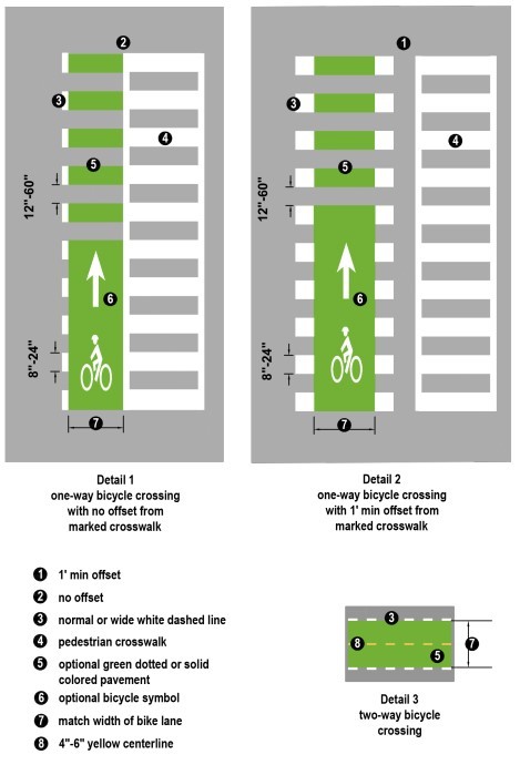
Figure 18-12: Bicycle Crossing Pavement Markings
(Refer to the
and
for additional signing and pavement marking guidance.)
18.3.12.2 Bicycle Signals
At signalized intersections, bicyclists may be controlled by motor vehicle signals, pedestrian signals, or bicycle signals. A bicycle signal provides a separate indication for the exclusive use of bicyclists. The use of a bicycle signal requires a “[BICYCLE] SIGNAL” (Signs R10-40 or R10-41) sign installed immediately adjacent to the traffic signal. Bicycle signals are typically used in the following situations:
- Two-way separated bike lanes;
- One-way separated bike lanes where the right-turn or left-turn motor vehicle movements across the separated bike lane exceed the thresholds in ;
- Where bicyclists’ position in the bikeway does not allow them to see motor vehicle or pedestrian signals that may otherwise be able to control their movement; and
- Where intersection complexity is such that signals are helpful, as determined by engineering judgment.
Bicycle signals can use a standard vehicle signal head with the R10-40 or R10-41 sign(s) or may use a signal with bicycle signal faces that comply with the requirements in FHWA’s Interim Approval (IA)-16. However, IA-16 has a specific requirement that bicycle signal faces may only be used if all bicycle movements are protected. An approved Request to Experiment from FHWA is needed for locations where permissive turns are allowed across a bike lane controlled by bicycle signal faces. Refer to the
for additional guidance on the use of Bicycle Signal Faces.
18.3.12.2.1 Considerations for Phase Separation
Designers should assess the number of right or left-turning motorists across sidepaths, raised bike lanes, or separated bike lanes which are physically separated from adjacent motorists during the peak hour to identify if permissive turns should be considered to manage potential conflicts which can arise due to their physical separation at the intersection.
identifies the thresholds where signal phase separation between bicyclists and turning motorists is recommended, but other factors such as the intersection complexity, number of signal phases, and engineering judgement should guide the designer’s decisions.
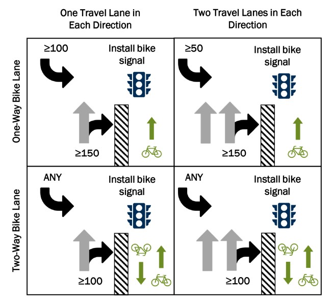
Figure 18-13: Signal Phase Separation of Turning Motorists
18.3.13 Bikeway Lighting
Fixed-source lighting can improve visibility along bikeways at night or under other dark conditions. Lighting can also greatly improve bicyclists’ ability to detect surface irregularities under such conditions, even when their bicycles are properly equipped with headlamps. Most bicycle trips occur during daylight hours, yet a relatively high incidence of crashes occur at night and dusk/dawn on roadways without bikeways. Nationally, 48 percent of bicyclist fatalities and 28 percent of bicyclist injuries occurred during the 12-hour period between 6 p.m. and 6 a.m.
Provision of lighting should be considered where night-time use of bikeways is anticipated and especially on:
- Bikeways that provide convenient connections to transit stops and stations, schools, universities, shopping, and employment areas;
- Under vehicular bridges, underpasses, tunnels, or locations with limited visibility;
- Along bridges used by bicycles and pedestrians;
- Along high use portions of bikeways that lead to areas with frequent evening events;
- At intersections where bikeways cross;
- At trail intersections with higher volume roadways; and
- At major trail entrances.
Designers should see
for information and guidance on the design of pedestrian scale lighting and appropriate illumination levels. Bikeway lighting should follow the same principles.
18.3.14 Restrict Motor Vehicle Use of Bicycle Facilities
Unauthorized use of shared use paths, on-street bicycle lanes, and separated bicycle lanes by motorists occurs occasionally. In general, this is a greater issue on shared use paths that extend through independent ROW that may appear to look like roadway or driveway entry points to motorists.
Per the
, the NO MOTOR VEHICLES (R5-3) sign can be used to clarify vehicle restrictions.
The routine use of bollards and other similar barriers (e.g., z-gates, fences) placed within the clear width of a bicyclists operating path to restrict motor vehicle traffic is not recommended. Bollards should not be used unless there is a documented history or anticipated high likelihood of unauthorized intrusion by motorists that results in injury. Barriers such as bollards, fences, or other similar devices used to limit access to bikeways create permanent obstacles to bicyclists, which can cause injury. Approaching bicyclists may shield these obstructions from a following bicyclist’s view until a point where the trailing rider does not have sufficient time to react which can contribute to crashes.
A strategy to minimize entry of motorists is to design the shared use path entry point as two sections separated by a conspicuous center island which may include low landscaping. The trail approach to the split should be delineated with solid line pavement markings to guide the path user around the island. Each half section of the path should be no more than 6 ft wide to discourage entry by motorized vehicles while still serving path users.
The center island and landscaping (if provided) should be designed to allow emergency and maintenance vehicles to enter the shared use path, if needed, by straddling the island and passing over the island and/or landscaping. Alternatively, it may be more appropriate to designate emergency and maintenance vehicle access via separate access drives adjacent to trail access points, which can be secured by gates or fencing. Such separate access drives should not be secured only by removeable bollards, as this may encourage potential use by trail users. Where a device to restrict motorists is determined to be necessary, consider the use of flexible or spring-mounted delineators before installing rigid bollards to reduce risk of potential injury to shared use path users. At locations where rigid bollards within the bikeway are determined to be necessary, the following should be provided:
- Bollards which are visible to approaching users meeting TxDOT specifications. Bollard placement should allow sufficient width for safe passage of bicyclists and other users by ensuring a minimum width of 6 ft is provided between bollard posts or a bollard and another vertical obstruction or edge of paved surface;
- Retroreflective pavement markings following guidance for obstructions on bikeways should be provided to guide users around the bollard; and
- For bollard retro-reflectivity, and color marking guidance, refer to the , and the applicable