18.4 Bikeway Types
This section provides a description and brief design guidance for the most common bicycle facility types. From left to right,
shows decreasing separation between bicyclists and motor vehicles. The bikeways presented on the left have the greatest appeal to the Interested but Concerned bicyclist (see
) since they have the most separation from motor vehicles.
A detailed description of each bikeway for urbanized contexts can be found starting in
through
. Rural contexts can be found in
. For additional guidance not stated herein, see additional design resources listed in
, which are sourced throughout this guide. It should be noted that different facility types may be used within different land use contexts or within the same land use context. Additionally, due to possible project site limitations, different facility types may be used to accommodate the origin and destination routes of bicyclists and pedestrians on each side of the roadway. For roadways on the
Texas Bicycle Tourism Trails Example Network
, provide appropriate Bike facility in coordination with the local community.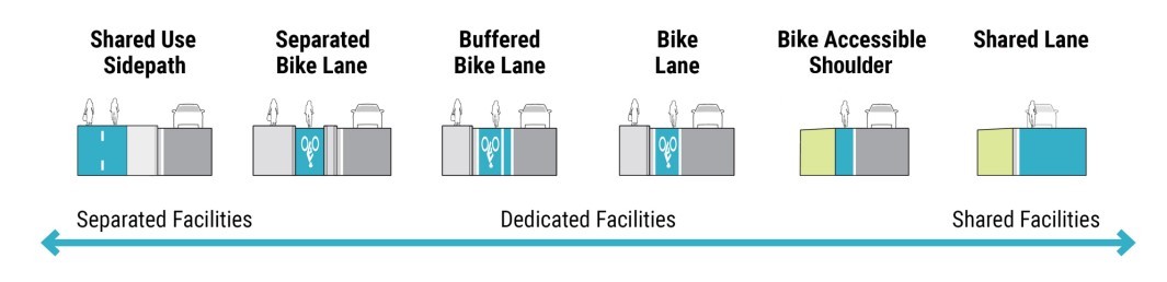
Figure 18-14: Bicycle facility Types by Level of Separation
18.4.1 Shared Use Paths Adjacent to Roadways (Sidepaths)
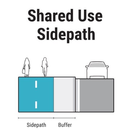
Figure 18-15: Example Shared Use Path Section
Shared Use Paths adjacent to roadways are located within a roadway corridor following the roadway alignment (hence the term sidepath) and are physically separated from motorized vehicular traffic by a landscaped buffer or a barrier. Sidepaths are generally designed for two-way travel, because in addition to bicyclists, users are likely to include inline skaters, skateboarders, pedestrians, and other micromobility or personal mobility device users. Sidepaths which do not provide adequate width may increase crash risk between people on the path.
Conflict points occur between motorists and path users at intersections and driveways. Of particular challenge is the contra-flow movement of higher speed users such as bicyclists. Conflict points should therefore be minimized and mitigated to the greatest extent practicable to maximize the comfort and safety of users operating on the facility (see
). The consolidation of driveways will reduce conflicts within the corridor.
Shared use paths may also be constructed with an independent alignment from a roadway which typically limits conflict points to midblock crossings of roadways. The shared use path on an independent alignment allows the vehicular driver to address the conflicts of the bicyclists exclusively, before proceeding to the roadway intersection and then addressing the standard conflicts with other vehicular traffic.
While the following guidance is written from the perspective of sidepaths located within roadway corridors, it is also applicable to shared use paths in independent alignments. Shared use paths in independent alignments often have fewer conflict points than sidepaths, however they may require the provision of more access points to provide connectivity to desired origins and destinations. The most common shared use path locations are through public property, parks, and abandoned railroad corridors. The
should be reviewed for additional guidance of shared use paths in independent alignments.
Refer to
for additional guidance on Shared Use Paths.
18.4.1.1 Application
Sidepaths are particularly useful when roadway width is limited and providing an on-street bikeway is not feasible. However, before defaulting to a sidepath, careful consideration should be given to potential conflicts between pedestrians and bicyclists as it is usually preferable to use separated bike lanes with sidewalks in urban areas and other locations where pedestrian volume is likely to result in conflicts between bicyclists and pedestrians as discussed in the width guidance.
For roadways with high driveway density, frequent street crossings, or overall high driveway volumes a one-way bicycle facility may be a more appropriate option, with an appropriate facility provided on each side of the roadway to provide needed origin and destination points. One-way bicycle facility preferred options include a separated or buffered bike lane. As identified in the
, for longer distances on urban and suburban streets with a considerable number of driveways and street crossings, two-way sidepaths can create operational concerns. Additional consideration should also be given with respect to parking configurations in the driveway vicinity that may tend to obstruct the sidepath usage or sight lines.
18.4.1.2 Width
When selecting a sidepath width, designers should consider the anticipated user volumes and mode split (bicycles, pedestrians, runners, etc.). The
is a helpful tool to inform a decision regarding the width of a path.
The Inputs into the SUPLOS calculator include the path width, trail user volume (one direction), trail user mix (mode split), and presence of a centerline stripe. The output is the calculated SUPLOS. A SUPLOS of “C” or better is desirable over the life of the facility to ensure it is comfortable and safe for all users.
provides an example calculation and set of typical inputs.
As a starting point for a new facility (without a shared use path), bike and pedestrian counts should be taken during the anticipated peak hour period on the existing roadway, and/or an analogous parallel facility which may provide a component of latent demand for the new shared use path. A reasonable factor should be applied for anticipated future growth of share use path usage. The
contains pedestrian and bicyclist count data for various types of facilities statewide and can be used to supplement missing information.
The desired width for a sidepath may range from 11-ft to 15-ft or more, depending on the SUPLOS calculation. These widths will accommodate higher user volumes while minimizing conflicts between them (based on the SUPLOS output). On a 12-ft sidepath, three “lanes” of users can operate simultaneously, allowing people to operate side-by-side while being passed by a person in the other direction (see
). To maximize service life and to assure a reasonable SUPLOS grade, paved widths should not be less than 10-ft.
As path user volumes increase, designers should consider increasing the width of the sidepath up to 15-ft. As path widths begin to exceed 15-ft in width, it may be desirable to separate pedestrians from bicyclists into sidewalk and separated bike lanes to minimize speed differential between pedestrians and wheeled users. Where it is determined to separate bicyclists and other higher-speed wheeled users from pedestrians (including people walking or using wheelchairs or other assistive devices) there are three primary strategies which can be considered for separating users on the facility (see
):
- A wide path can be provided which separates users using pavement markings
- A wide path can be provided which separates users with a traversable surface delineation;
- Separate paths can be used which are physical separated from each other.
Alternatively, a separate bicycle facility type may be selected.
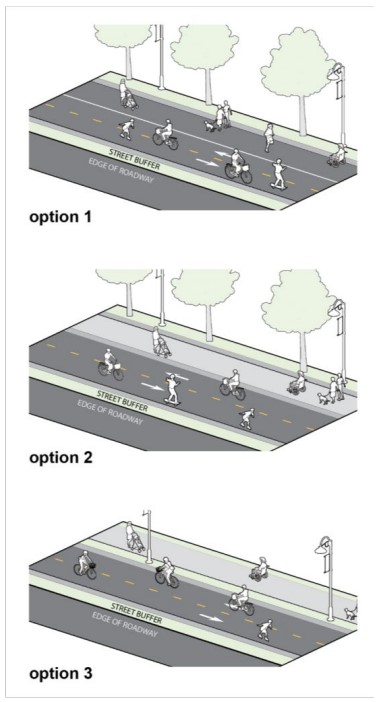
Figure 18-16: Potential Options for Separation of Shared Use Paths
The standard
minimum width
is 10-ft. A minimum width
of 8-ft may be used in rare circumstances where all the following conditions are met:- Bicycle traffic is expected to be low (< 50 bicyclists/hour) during peak hours on the path;
- Pedestrian use of the facility is not expected to be more than occasional or less than 30% of total path traffic;
- Horizontal and vertical alignments provide frequent, well-designed passing and resting opportunities where the width is at least 10-ft; and
- The path will not be regularly subjected to maintenance vehicle loading conditions that would cause pavement edge damage.
In
constrained conditions
, a minimum width of 8-ft may be used for short distances to avoid physical constraints such as bridge abutments, utility structures, and environmental constraints.Segment Name | Path Width | Centerline | Volume (users per hour in 1 direction) and Mode Split | ||||||
Name | Width (ft | 1=Center-line | One-Way (per hour) | Adult Bicyclists | Peds | Runners | In-Line Skaters | Child Bicyclists | SUPLOS grade |
More Peds | 12.0 | 0 | 100.0 | 20.0% | 60.0% | 15.0% | 2.0% | 3.0% | C |
18.4.1.2.1 Street Buffer Width and Considerations
The space between the inside edge of sidepath and adjacent edge of outside travel lane (uncurbed), or face-of-curb (if curbed) is the street buffer. It is desirable to provide as much distance from the road as is practicable given project conditions.
The
minimum street buffer
is shown in
Roadway and Speed Condition | Minimum Street Buffer |
Curbed low-speed (45 mph or less) | 4-ft from FOC 1 |
Curbed high-speed (50 mph or greater) | 6-ft from FOC 1 |
Uncurbed all speeds | 10-ft |
Notes: | |
1. For curb and gutter sections with a shoulder, bike lane or any buffer in addition to the curb offset the minimum street buffer measurement begins at the edge of through travel lane (through travel lanes do not include turn lanes, accel lanes, or decel lanes). This minimum width is 10-ft. The required minimum street buffer for the sidepath then becomes the lesser of the 10-ft measurement, or the face of curb (FOC) minimum in Table 18-6. | |
The desirable street buffer would be the respective desirable clear zone values from
. Increasing the buffer width in the vicinity of driveways provides better alignment and visibility and is beneficial to all users.
A minimum shy space of 2-ft should be provided to intermittent (e.g., signs, streetlights, and utility poles) and continuous (e.g., walls, railings, fences, and barriers) vertical objects to minimize crash risks and increase the comfort of path users. Where space is available, wider shy spaces are desirable. In constrained conditions, the shy space may be reduced to 1-ft except to post mounted signs.
A graded shoulder with a minimum 2-ft width, 5- ft desirable, and a maximum cross-slope of 1V:6H should be provided on both sides of all shared use paths where natural terrain is present adjacent to the path alignment.
Where a bikeway is adjacent to a hazardous condition such as a parallel body of water or steep downward slope, a shoulder between the bikeway and the top of the slope of 5-ft is desirable. For steep slopes where the shoulder is less than 5-ft, physical barriers or rails are recommended in
. Specific railing considerations for bicyclists are provided in
.
18.4.1.2.2 Signing and Marking
Signs installed in the vicinity of sidepaths shall be installed in accordance with the applicable
criteria.
The
requires that no portion of a sign or its support be placed within 2-ft laterally from the near edge of a shared use path. Where space is available, wider shy spaces are desirable.
Refer to
– Section 9C.03 Marking Patterns and Colors on Shared Use Paths for information about markings for sidepaths. Additional information is provided in
regarding mid-block shared use path crossings.
18.4.1.2.3 Bicyclist Design Speed
A target design speed of 15 mph is generally appropriate to accommodate bicyclists on a shared use sidepath given the fact bicyclists are operating with pedestrians and may encounter driveways and intersections due to the alignment alongside the roadway.
For shared use paths with lower volumes of users expected now and in the future, a design speed of 18 to 30 mph may be appropriate where pedestrian volumes are low (less than 30 percent). The primary purpose of the shared use path is to provide a higher speed bicycling opportunity between destinations.
On unpaved path surfaces, bicyclists tend to travel slower to compensate for reduced braking ability, so a lower design speed of 12 mph may be used.
18.4.1.2.4 Cross Slope and Grade
Cross slopes of 1 to 1.5% percent are more comfortable for people with disabilities and people bicycling with more than two wheels (e.g., cargo bike, adult tricycles, or trailers). To meet pedestrian accessibility guidelines the cross slope cannot exceed 2.0 percent.
For shared use paths on independent alignments, longitudinal grades must meet pedestrian accessibility guidelines as they are expected users of the facility.
provides minimum design guidance for pedestrian accessibility of shared use paths.
reinforces that grades on shared use paths on an independent alignment are limited to 5 percent to maximize pedestrian accessibility.
Certain conditions such as physical constraints (existing terrain or infrastructure, notable natural features, etc.) or regulatory constraints (endangered species, the environment, etc.) may prevent full compliance with the 5 percent maximum grade. In those cases, mitigations should be considered to assist pedestrians. Grades may also exceed 5 percent at overpasses and underpasses if ramps and landings complying with
, Section R407, are provided.Options to mitigate excessive grades on shared use paths include the following:
- Use higher bicycle design speeds for horizontal and vertical alignments, stopping sight distance, and other geometric features;
- When steep grades occur over a long distance, consider an additional 4 to 6-ft of width to permit slower bicyclists to dismount and walk uphill, and to provide more maneuvering space for faster downhill bicyclists (see );
- Install the Hill Warning Sign for Bicyclists (W7-5) and advisory speed plaque in conditions where the steep grade is unexpected and not visible;
- Exceed minimum shy distances, add recovery areas and/or protective railings;
- If other designs are not practicable, use a series of short switchbacks to traverse the grade. If this is done, an extra 4-ft to 6-ft of path width is recommended to provide maneuvering space at each horizontal curve used to form the switchback;
- Provide resting intervals with flatter grades to permit users to stop periodically and rest; and
- Consider the provision of accessible pedestrian handrails.
Note
: Grades steeper than 3 percent may not be practical for shared use paths with crushed stone or other unpaved surfaces for both bicycle handling and drainage erosion reasons.When shared use paths follow the same alignment of the roadway, the sidepath grades will typically match the grade of that adjacent roadway. A sidepath within the roadway ROW of a road with a grade that exceeds 5 percent may not exceed the adjacent roadway grade.
18.4.1.3 Horizontal Geometric Design
provides the minimum radii for horizontal curves for paved shared use paths for various design speeds. These values use a 20-degree lean angle.
In general, a greater than 60-ft radii is preferred for horizontal alignment. For Shared Use Paths 10-ft or less in width in constrained locations where environmental or physical constraints limit the ability to apply a 60-ft radius, slower design speeds (12 to 16 mph) may be appropriate to allow the use of sharper horizontal curves to minimize impacts; however, the design should not result in a path with continuous combination of sharper curve. In these situations, wider paths or curve widenings of 2-ft to 4-ft should be considered to let users navigate the effects of substandard curves.
The
should be consulted where it is desired to develop curves using the superelevation method keeping in mind that shared use paths must meet accessibility guidelines which limit cross slopes to a maximum of 2.0 percent
Design Speed (mph) | Minimum Radius (ft) |
8 | 12 |
10 | 18 |
12 | 27 |
14 | 36 |
15 | 41 |
16 | 47 |
18 | 60 |
20 | 74 |
25 | 115 |
30 | 166 |
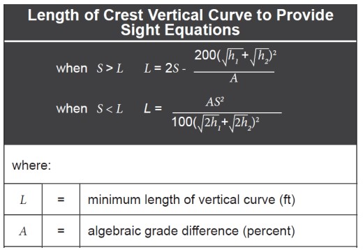
18.4.1.4 Vertical Geometric Design
provides the vertical curve length needed based on stopping sight distance and algebraic grade difference on crest vertical curves.
provides the equation for calculating this length for scenarios not shown in
. A recumbent bicyclist is recommended to establish design criteria and the following assumptions should be used:
- The eye height of the recumbent bicyclists is 3.83-ft; and
- The object height is at the ground surface (i.e., 0-in) to recognize that impediments to bicycle travel can exist at pavement level.
Table 18-8: Minimum Vertical Curve Length Based on Stopping Sight Distance
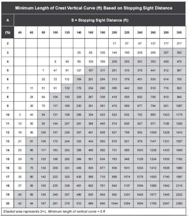
Table 18-9: Crest Vertical Curve Equation
18.4.1.5 Other Considerations
Crashworthy barriers, when used on locations with sidepaths, should be located between the roadway and sidepath. A minimum of 1-ft of shy distance is needed between the vehicular traffic and the barrier, and between the sidepath traffic and the barrier.
On roadways which do not have roadside obstacles requiring a barrier, a barrier or railing may be considered to improve path user safety where the facility has all these conditions present:
- The road is uncurbed;The road is uncurbed;
- If shoulders are present, the road has shoulders less than 4-ft in width; and
- The road is a high-speed facility.
provides additional details on the design of barriers and railings. Designers should see
for further details on bridges and underpasses for shared use paths
To improve the safety of contra-flow bicyclists who may be unexpected by motorists, the following measures should be considered during design:
- Provision of 6 to 20-ft street buffers at crossings to create space for motorists to stop and yield to path users while turning;
- Provision of clear sight lines allowing motorist to see approaching bicyclists, pedestrians, and motorists;
- Provision of traffic control signs, and clearly marked bicycle crossings following (Part 9) to alert motorists of bicycle travel;
- Reduction and consolidation of driveways to the greatest extent practicable to reduce conflict points;
- Constructing driveways at sidewalk level to emphasize bicycle use along a sidepath to motorists entering/exiting driveways to slow turning motorists and improve their likelihood of stopping and yielding to crossing path users; and
- At signalized intersections consider:
- Provide a leading interval or phase separation to minimize conflicts where path volume exceeds 100-150 users/hour and right turning vehicle volume exceeds 100 vehicles/hour;
- Provide a leading interval or phase separation to minimize conflicts where path volume exceeds 100-150 users/hour and left turning vehicle volume exceeds 50 vehicles/hour or roadway operating speeds exceed 35 mph; and
- Prohibit right turns on red where vehicles frequently block the crosswalk.
Each end of a sidepath should directly connect to an on-street bike facility, another trail or path, or to a bicycle-compatible local street. Where no interconnecting bikeways exist, advanced signage should be installed informing roadway users that the path ends, and bikes may use the full lane. Additional signage in conformity with
can be provided that directs bicyclists to interim facilities along alternate routes.
The minimum vertical clearance to obstructions over the path that may be used in constrained areas is 8-ft. The desirable vertical clearance to obstructions is 10-ft. In some situations, vertical clearance greater than 10-ft may be needed to permit passage of maintenance and emergency vehicles, or where equestrian use may be expected.
18.4.2 Separated Bike Lanes
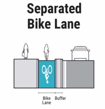
Figure 18-17: Example Separated Bike Lane Schematic
A separated bike lane is a bicycle lane that is physically separated from the adjacent motor vehicle traffic by vertical elements in the street buffer. They typically are designed to operate one-way but may also operate two-way. These are sometimes also referred to as protected bike lanes or cycle-tracks. Separated bike lanes combine the user experience of a shared use sidepath with a designated area for bike use only like a conventional bicycle lane, separate from pedestrians. They are distinct from the sidewalk but may be at sidewalk level (see Cambridge, MA, example). Vertical elements separating the bike lane from the travel lane may include continuous raised medians, flexible posts, intermittent concrete curbing (see Austin, TX, example), or parked vehicles
Separated bicycle lanes are more appealing to a wider range of bicyclists on higher volume and higher speed roads than striped bike lanes. They avoid the conflict with an opening car door and prevent motor vehicles from driving, stopping, or waiting in the bikeway. They also provide greater comfort to pedestrians by separating them from bicyclists operating at higher speeds and further separating pedestrians from motor vehicles. Full guidance can be found in FHWA Separated Bike Lane Planning and Design Guide,
and the
. See
for examples of separated bike lanes.
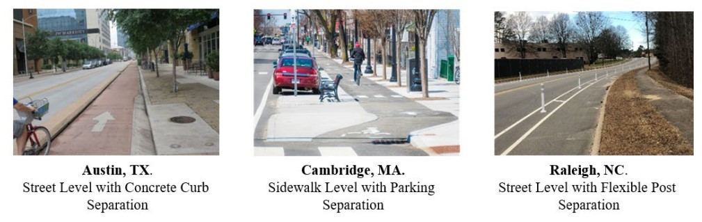
Figure 18-18: Examples of Separated Bike Lanes by Separation Types
The cross section of a separated bike lane has three distinct zones (see
):
- Bike lane– The bike lane is the space in which the bicyclist operates. It is located between the street buffer and the sidewalk buffer.
- Street buffer– The street buffer separates the bike lane from motor vehicle traffic.
- Sidewalk buffer– The sidewalk buffer separates the bike lane from the sidewalk.
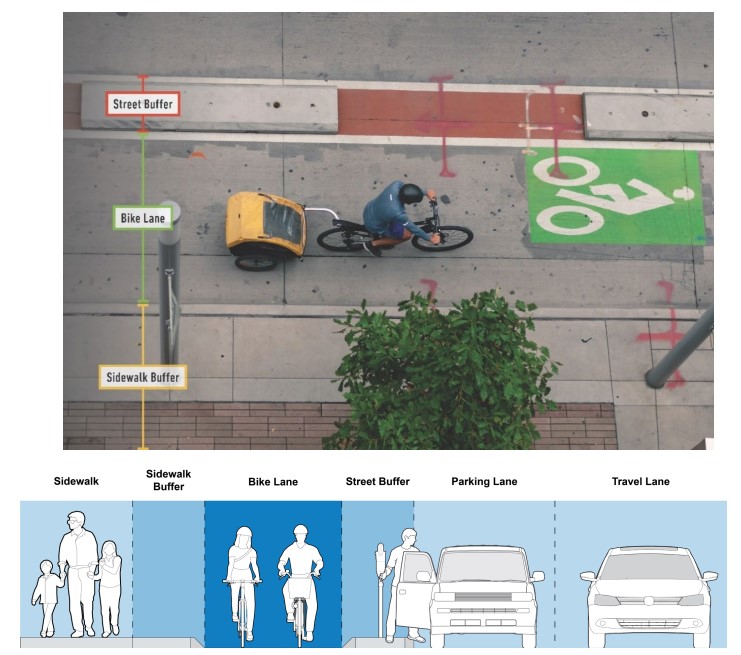
Figure 18-19: Separated Bikeway with Three Distinct Zones
18.4.2.1 Application
Raised medians, curbs, or other low-profile, hard separated bike lanes should only be used in locations with speeds of 45 mph or less.
Separated bike lanes with flexible posts or crashworthy barriers are allowable for highspeed roadways.
Raised separated bike lanes (at sidewalk level) are allowable for all speeds.
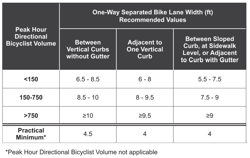
18.4.2.2 Bike Lane Width
The desirable width of a separated bike lane depends upon the volume of users and the context of the design as shown in
for one-way separated bike lanes. Two-way separated bike lane widths should follow the previous guidance in
(Shared
Use Path Widths). The use of constrained dimensions should only be considered:
- For limited distances;
- As an interim measure where the larger values will result in the preferred design not being constructible; and
- At locations with low volumes of bicyclists where those volumes are anticipated to remain low (< 50 bicyclists/hour).
- See for guidance on buffers on two-way separated bike lanes.
Table 18-10: One-Way Separated Bike Lane Widths (Recommended)
The sidewalk buffer zone separates the sidewalk from the separated bike lane to communicate the sidewalk and the separated bike lane are distinct spaces. There is no minimum width, however, it is necessary to consider the needs of vegetation or street furniture if that is provided as the buffer. Sidewalks buffers need to include a detectable edge so pedestrians with vision disabilities can distinguish between the bike lane zone and the sidewalk. The sidewalk buffer zone may include:
- Street furniture or other vertical elements (such as a row of street trees);
- Continuous landscaping; or
- A curb to separate the bike lane from the adjacent sidewalk.
Separated bicycle lanes that are raised to sidewalk level with a wider buffer from traffic provide a high level of separation from traffic, but often require road reconstruction. The street buffer between the bike lane and travel lanes is needed to improve bicyclists’ comfort and to create space for vertical elements to reinforce the separation:
- For one-way separated bike lanes separated from vehicular traffic by a raised median or curb (low-speed), a minimum 2-ft buffer (measured from face of curb to face of curb) is required (see above);
- For non-curbed separated bike lanes, a minimum of a 2-ft buffer is required for low-speed conditions, and 3-ft for highspeed conditions;
- Additional buffer area is recommended to improve bicyclists’ comfort and to increase separation between bicyclists and vehicular traffic;
- See the for guidance on buffers on two-way separated bicycle lanes. Two-way separated bicycle lanes also need to meet the guidance in and with respect to intersecting driveways, and conflict points; and
- In scenarios where there is none, or limited space for a street buffer, designers may consider a raised bike lane, see
Continuous or intermittent vertical elements such as raised medians or flexible delineator posts are needed in the street buffer to provide separation between motor vehicle traffic and the bike lane. Designers should ensure that the vertical elements are visible to approaching bicyclists and motorists. In some cases, vertical elements should be supplemented with a striped buffer to clearly delineate the buffer zone. The placement of vertical elements within the street buffer should also consider the need for shy distance to the bikeway and to the travel lane, and the door-swing of parked cars adjacent to areas of on-street parking. See
for additional guidance for the marking of buffers.
18.4.2.3 Signing and Marking
18.4.2.4 Bicyclist Design Speed
For separated bike lanes in urban areas, a target design speed of 15 mph is generally appropriate. Higher design speeds may introduce safety challenges where bicyclists interact with motorists and pedestrians. Lower bicyclist and motorist operating speeds at conflict points allow bicyclists and motorists more time to perceive potential conflicts. This is particularly important at intersections with separated bike lanes.
18.4.2.5 Cross Slope and Grade
Cross slopes of 1 percent are more comfortable for people with disabilities and people bicycling with more than two wheels (e.g., cargo bike, adult tricycles, or trailers); however, cross slope may match existing roadway conditions without a maximum where necessary
18.4.2.6 Other Considerations
Separated bicycle lanes that are protected from traffic by a row of on-street parking offer a greater degree of separation. Additional vertical elements may be required to keep parked vehicles within the parking lane.
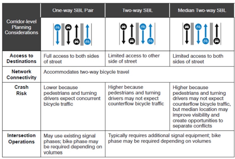
During the concept design stage for a separated bikeway, it is necessary to determine if it would be more appropriate to place a one-way separated bike lane on each side of the street, or to place a two-way separated bike lane or sidepath on one or both sides of the street. Selecting the appropriate configuration requires an assessment of many factors, including safety, overall connectivity, ease of access, available ROW, curbside uses, intersection operations, ingress and egress at the termini, maintenance, and feasibility.
and
provide an overview of trade-offs for various scenarios.
Table 18-11: Separated Bike Lane Configurations on a One-Way Street
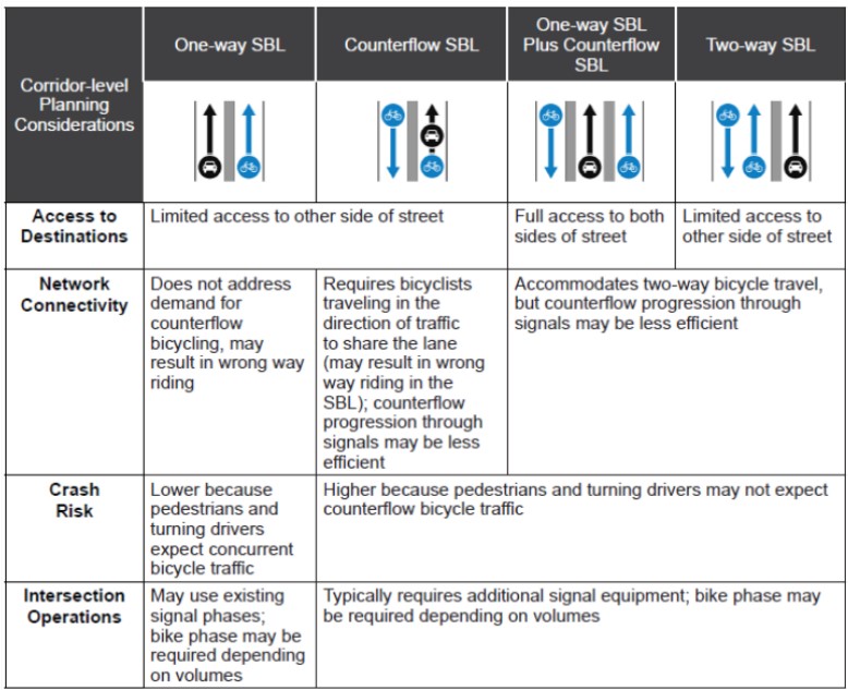
Table 18-12: Separated Bike Lane Configurations on a Two-Way Street
NOTE: A raised curb separator on a separated bike lane may be a tripping hazard if it is located near a pedestrian path. Mitigation may include high visibility markings, offset the raised curb separator from the crosswalk, and add flexible delineators.
18.4.3 Buffered Bike Lanes
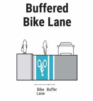
Figure 18-20: Example Buffered Bike Lane Schematic
A buffered bike lane is a one-way bike lane that is separated from the adjacent motor vehicle lane or parking lane by a striped buffer area that may include chevrons, diagonal lines, or wide pavement marking stripes. When sufficient roadway width is present, or if the number of travel lanes is reduced, a buffer may be striped between a bike lane and travel lane to provide additional comfort for both bicyclists and motorists. This provides space for bicyclists to pass one another or ride side by side without encroaching into a motor vehicle travel lane. The buffer adds to the perception of safety and encourages greater use of the on-street bicycle network. Providing added separation between motorists and bicyclists who may be traveling at substantially different speeds appeals to a wider array of bikeway users.
18.4.3.1 Application
See
in
for initial recommendations on when to use a buffered bike lane. The criteria below defines the criteria for all available applications for all speeds.
18.4.3.2 Bike Lane Width
The desirable useable width of a buffered bike lane is 5 to 7-ft exclusive of the buffer. The minimum useable width is 4-ft exclusive of the buffer. The usable width of the bike lane is measured from the outside buffer stripe to either the gutter joint or 1-ft from the nominal face of a monolithic curb.
18.4.3.3 Buffer Width and Considerations
Buffers should be a minimum of 2-ft wide for speeds of 45 mph or less, and 3-ft wide for 50 mph or greater.
Buffers generally consist of a combination of standard longitudinal markings and crosshatching. Diagonal or chevron crosshatch markings are optional; however, they are recommended in locations with buffers that exceed 2-ft in width.
Where provided, crosshatching should be provided at a regular interval. Typical spacing is 20-ft with some locations reduces to as low as 5-ft where engineering judgement determines a more frequent spacing is desirable. See
for examples of bike buffer lane types.
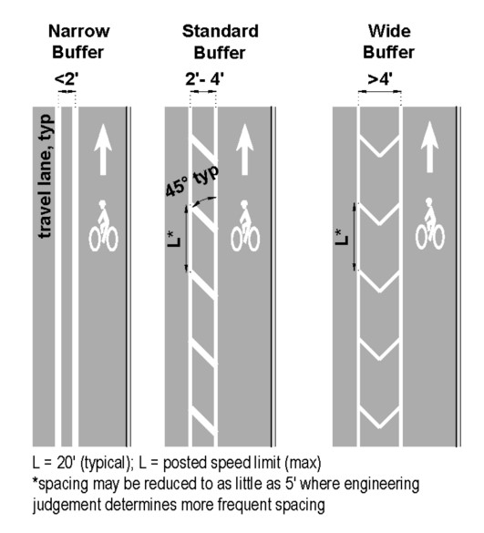
Figure 18-21: Examples of Buffered Bike Lane Types
18.4.3.4 Signing and Marking
The stripe near the travel lane should be 6-in wide, while the stripe near the bicycle lane can be four inches. If buffer is 3-ft wide, diagonal hatching should also be marked. If buffer is wider than 3-ft, chevron hatching should also be marked.
Buffers can be striped between travel lanes and bike lanes, between bike lanes and parking lanes, or both.
Bicycle markings and signage should be used and are the same as a conventional bike lane.
18.4.3.5 Bicycle Design Speed
Not applicable as the roadway will be designed to accommodate motorist target design speeds which will exceed bicyclist’s design speed.
18.4.3.6 Cross Slope and Grade
Not applicable.
18.4.3.7 Other Considerations
Not applicable.
18.4.4 Bike Lanes
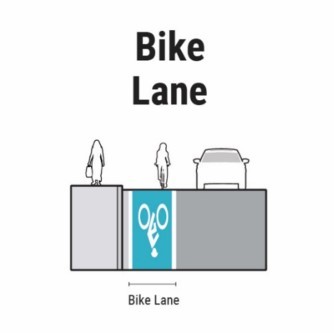
Figure 18-22: Example Bike Lane Schematic
Bike lanes are one-way facilities on a roadway that typically carry bicycle traffic in the same direction as adjacent motor vehicle traffic. Bike lanes are provided for the exclusive use of bicyclists and are identified through signage, striping, or other pavement markings. These lanes allow bicyclists to ride at comfortable speeds and encourage a position within the roadway where they are more likely to be seen by motorists. Bike lanes are typically on the right side of the street, between the outside travel lane and curb, parking lane, or road edge. While the bike lane distinguishes predictable areas for bicyclist and automobile movement, bicyclists may leave the bikeway to pass other bicyclists or avoid debris and other traffic conflicts.
18.4.4.1 Application
Bike lanes should only be used in locations with speeds of 45 mph or less. For high-speed locations, a buffered bike lane is recommended.
In locations where space allows and additional protection and conspicuity is desired, designers may consider a raised bike lane, see
. This can be particularly beneficial at intersections, see
.
18.4.4.2 Width
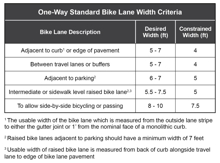
The width of a bike lane has a significant impact on a bicyclists’ comfort and their central operating position within a bike lane. See
for one-way standard bike lane width criteria. As the adjacent motorized traffic volume and speed increases, or as the relative percent of heavy vehicles increases, bicyclists will try to move away from vehicles operating in the adjacent travel lane, positioning themselves closer to parked vehicles or the edge of roadway which can increase their crash risk.
Table 18-13: One-Way Standard Bike Lane Width Criteria
18.4.4.3 Signing and Marking
A solid white edge line (6-in wide) should be placed between the bike lane and travel lane. Lane lines between parked cars and the bike lane are optional.
Standard bike lane symbols and arrows, per the
, should be used to inform bicyclists and motorists of the restricted nature of the bike lane, and markings should be placed at periodic intervals to remind motorists of the presence of bicyclists.
Bike lane symbol markings should be placed no more than 50-ft downstream from an intersection. The first marking after an intersection or driveway should be placed outside of the wheel path of turning vehicles to reduce wear:
- In urban areas, it may be appropriate to space the symbols closer than 250-ft where motorist conflicts may be higher such as approaches to areas with significant parking turnover, intersections, driveways, or turn lanes; and
- In suburban and rural areas, with long distances between intersections and little roadside activity, bike lane symbols may be spaced 1,000-ft apart or more.
18.4.4.4 Bicycle Design Speed
Not applicable as the roadway will be designed to accommodate motorist target design speeds which will exceed bicyclists.
18.4.4.5 Cross Slope and Grade
Not applicable.
18.4.4.6 Other Considerations
The effective width of a bike lane should not include rumble strips or standard drainage inlets.
Drainage grates located in the bike lane should be designed to prevent bicycle tires from catching in the grate pattern. See
for more information on drainage inlet grates in bicycle facilities
18.4.5 Raised Bike Lanes
A conventional bicycle lane can be raised above the street grade to create more separation from vehicles when a separated bike lane (see
) with horizontal separation is not feasible or desired. In general, a separated bike lane is preferable to a raised bike lane to prevent motor vehicle encroachment and to reduce the potential for a bicyclist to crash while transitioning from the raised bike lane to the roadway at intersections. While a mountable curb between the raised bike lane and travel lane can reduce crash risk for bicyclists, it will not discourage motorists from encroaching into the raised bike lane. Raised bike lanes should not be installed adjacent to on-street parking due to the greater risk of dooring.
Raised bike lanes can be raised slightly, between street level and sidewalk height (intermediate level), or it can be located at sidewalk height (sidewalk level). Specific information on the curb types adjacent to raised bike lanes are discussed in
.
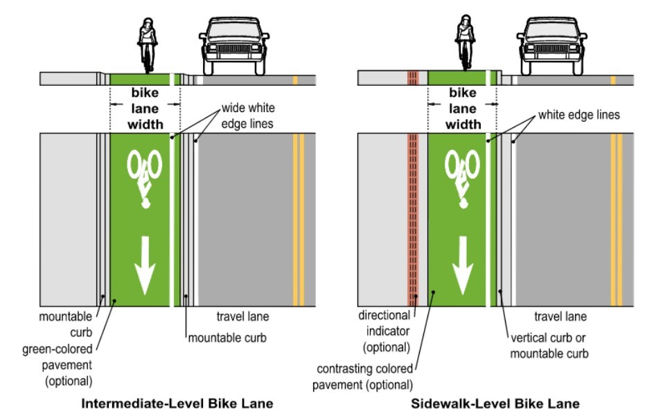
Figure 18-23: Raised Bike Lane Considerations
(Refer to the
and
for additional signing and pavement marking guidance.)
18.4.5.1 Application
A raised bike lane can be paired in a corridor with either a separated bike lane or a conventional bike lane in scenarios where cross sections vary and/or additional conspicuity is desired for the bikeway users. These are most commonly used on roadways which do not have sufficient width to provide separated bike lanes with desirable street buffers where the alternative would be to provide a standard bicycle lane. Raised bike lanes require bicyclists to merge into the travel lane or a standard bike lane at intersections or to transition to a sidewalk (see
).
18.4.5.2 Width
The width of raised bike lanes should accommodate the anticipated bicyclist demand and reduce the likelihood that a bicyclist will have to transition to an adjacent travel lane or sidewalk to pass other bicyclists or to avoided hazards such as debris, surface defects, or objects in the bike lane. The width should also consider the elevation of the bike lane.
provides minimum and constrained widths for both raised bike lane scenarios
18.4.5.3 Signing and Marking
A white edge line should be located at the edge of the travel lane to clarify the boundary with the bike lane. A wide white edge line may be used, but it is recommended at locations with an intermediate height bike lane to provide additional emphasis of the mountable curb or the lower height curb (see
). To further differentiate the raised bike lane from an adjacent travel lane or sidewalk and increase awareness of the elevation change the raised bike lane may:
- Be built with contrasting paving materials;
- Include a normal width white edge line adjacent to the sidewalk curb; and/or
- Include BIKE LANE (R3-17) regulatory signs.
18.4.5.4 Bicycle Design Speed
For raised bike lanes, a target design speed of 15 mph is generally appropriate as these bikeways are typically narrower than separated bike lanes and bicyclists do not have the ability to enter the roadway. Higher design speeds may introduce safety challenges where bicyclists interact with motorists and pedestrians. Lower bicyclist and motorist operating speeds at conflict points allow bicyclists and motorists more time to perceive potential conflicts. This is particularly important at intersections with raised bike lanes where bicyclists must merge into the roadway or enter a shared pedestrian space.
18.4.5.5 Cross Slope and Grade
Cross slopes of 1 percent are more comfortable for people with disabilities and people bicycling with more than two wheels (e.g., cargo bike, adult tricycles, or trailers) while allowing for adequate conveyance of drainage; however, cross slope may match existing roadway conditions without a maximum where necessary.
18.4.5.6 Other Considerations
To prevent motor vehicle encroachment into the bike lane, a sidewalk-level raised bike lane built with a curb between the bike lane and travel lane is preferred. Where sidewalks are adjacent to the raised bike lane, a detectable edge should be provided to reduce the likelihood people with vision disabilities will enter the bike lane. This may lead to the construction of an intermediate-level bike lane.
provides additional guidance for sidewalk buffer design.
At locations where an intermediate-level raised bike lane is less than 7-ft in width, the bike lane should have a continuous mountable curb on both sides, between the bike lane and travel lane and the bike lane and the sidewalk, allowing bicyclists to traverse the curb if necessary. While the provision of a curb along the travel lane is more likely to discourage motorists from entering the raised bike lane, it may also decrease the comfort and safety of bicyclist if the bike lane is not sufficiently wide or if it is necessary for the bicyclist to exit the bike lane.
The bike lane elevation may vary within a single corridor via bicycle transition ramps which raise or lower the bike lane as needed at pedestrian crossings, transit stops, driveways, and intersections. Additional details on the design of intersections are discussed in
later in this guide. Frequent elevation changes along a corridor should be avoided because they reduce the comfort of the bicycling environment and can create maintenance challenges.
Raised bike lanes will require special considerations for maintenance activities as it may be difficult to maintain a debris free surface with standard street maintenance practices. For example, street sweepers cleaning an adjacent travel lane may push additional debris onto an intermediate level bike lane. Additionally, drainage will be based on the curb type used and may require inlets instead of drainage grates.
Raised bike lanes on roadways with frequent driveways should be considered carefully. The driveway design may require the bikeway to be lowered, resulting in frequent elevation changes which may be uncomfortable.
18.4.6 Bike Accessible Shoulders
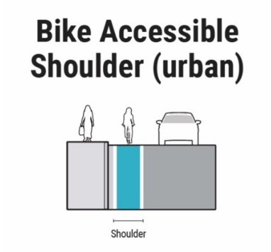
Figure 18-24: Example Bike Accessible Shoulder Schematic
Bike accessible shoulders are one-way facilities on a roadway that carry bicycle traffic in the same direction as adjacent motor vehicle traffic. A bike accessible shoulder is one that is at least as wide or wider than a bike lane to accommodate bicyclists and paved to provide a smooth, solid surface across its width. While the bike accessible shoulder distinguishes areas for bicyclist and automobile movement, bicyclists may leave the shoulder to pass other cyclists or avoid debris and other traffic conflicts.
18.4.6.1 Application
See
for guidance on recommended shoulder width. In rural environments, see
for guidance on desirable shoulders widths.
18.4.6.2 Width
For any given roadway, the determination of the appropriate paved shoulder width should be based on the roadway’s context and traffic conditions following the guidance in
for shoulder requirements on new location and reconstruction projects. However, it should be noted that the shoulders in the RDM may consist of graded (soft) and paved (hard) surfaces. To ensure accommodation of bicyclists, it is desirable for paved shoulders to conform to the widths in
.
Some shoulders should be up to 10-ft wide adjacent to higher speed roadways as indicated in
to allow bicyclists to operate with more separation to the high-speed traffic. Roadways indicated in TxDOT’s Bicycle Tourism Trails Study should be designed with a 10-ft shoulder (8-ft minimum) shoulder, a shared use path, or another locally preferred facility type should be available. Contact TxDOT’s Public Transportation Division (PTN) for more information. The minimum widths for a bike accessible shoulder are defined below.
- A minimum width of 4-ft is allowable in low speed (45 mph or less) conditions;
- A minimum width of 5-ft is allowable for high-speed conditions; and
- A minimum width of 5-ft is required for shoulders adjacent to bridge railings, MBGF, and other vertical elements.
The width of the bike accessible shoulder does not include rumble strips. See below for more information on rumble strip considerations.
18.4.6.3 Signing and Marking
A solid white edge line (6-in wide) should be placed between the shoulder and travel lane.
Bike accessible shoulders typically do not have bike lane markings, but they may include signage indicating the presence of bicyclists.
A bike accessible shoulder may transition to a bike lane with signage and markings at intersections to communicate the exclusive use of the space by bicyclists.
18.4.6.4 Bicycle Design Speed
Not applicable as the roadway will be designed to accommodate motorist target design speeds which will exceed bicyclists.
18.4.6.5 Cross Slope and Grade
Cross slopes of 1 percent are more comfortable for people with disabilities and people bicycling with more than two wheels (e.g., cargo bike, adult tricycles, or trailers) while allowing adequate conveyance of drainage; however, cross slope may match existing roadway conditions without a maximum where necessary.
18.4.6.6 Other Considerations
Rumble strips are used to warn the driver that they are leaving the travel way and therefore may have a beneficial effect on the safety of bicycles using the shoulder. If rumble strips are to be used, or are anticipated in the future, allowances should be made in the shoulder to provide an adequate width for bike accommodations beyond the rumble strip.
Profile pavement markings serve a similar function as milled rumble strips and can be considered as an option to avoid a reduction in the width of the accessible shoulder. Where bicycle traffic is expected, rumble strips should be designed as follows to minimize crash risk for bicyclists (see
). Refer to the latest RS Standards for additional guidance on rumble strips.
Periodic gaps (
) should be provided to allow bicyclists to safely enter or exit a shoulder as needed (e.g., to avoid debris, pass other bicyclists or disabled vehicles, make left turns, etc.) without having to ride over the rumble strips.
- Where bicyclists are operating at 20 mph or less, a minimum 15-ft gap every 40 to 60-ft allows half a second for a bicyclist to cross the rumble strip; and
- Where bicyclists are operating over 20 mph, the gap should be increased to 20- ft or more or the rumble strips should be located on the right side of the shoulder to allow bicyclists to avoid them if they encounter a need to enter the travel lane (e.g., a downhill location).
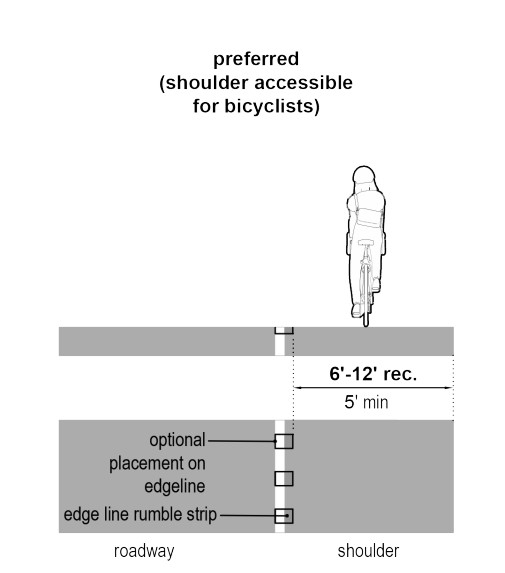
Figure 18-25: Rumble Strip Placement in a Shoulder
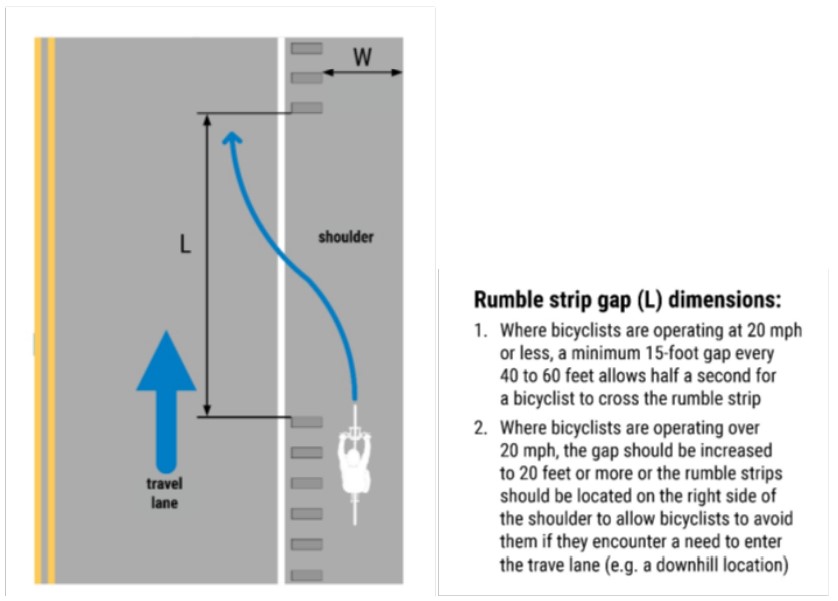
Figure 18-26: Rumble Strip Design and Gap Placement
18.4.7 Shared Lanes (wide outside lane)
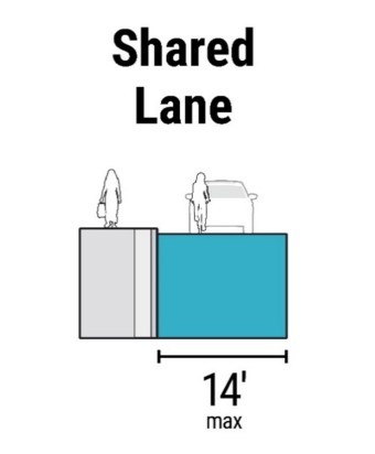
Figure 18-27: Example Shared Lane Schematic
Shared lanes (wide outside lane) are lanes that allow compatibility of operation for both motorized vehicles and bicycles. Since bicycles may be operated on all roadways except where prohibited by statute or regulations, shared lanes without markings already exist in many different urban, urban core, suburban and rural town settings.
Note that although marked shared lanes are allowed in the
for certain conditions, TxDOT as a general policy does not recommend marked shared lanes for TxDOT roadways due to the higher speed nature of TxDOT roadways as compared to local jurisdictions.
18.4.7.1 Application
Shared wide outside lanes in urbanized applications should only be used in locations with low volumes (3,000 ADT or lower) and low speeds (35 mph or less).
18.4.7.2 Width
The usable width for a wide outside lane should be 14-ft maximum and 13-ft minimum. The usable width is measured from the lane stripe to either the gutter joint or 1-ft from the nominal face of a monolithic curb.
If the usable width is greater than 14-ft, a bike lane should be provided instead. Use of minimum travel lane widths may be necessary to incorporate the bike lane.
18.4.7.3 Signing and Marking
Typical supplemental signage may include: BICYCLES MAY USE FULL LANE (R4-11). Refer to the
for signing applications.
Custom signage may include language instructing vehicles to change lanes to pass or use a 3-ft passing distance.
18.4.7.4 Bicycle Design Speed
Not applicable as the roadway will be designed to accommodate motorist target design speeds which will exceed bicyclists.
18.4.7.5 Cross Slope and Grade
Not applicable.
18.4.7.6 Other Considerations
Lighting can be a beneficial element for Shared Lane facilities. It can significantly enhance safety and visibility for cyclists, particularly at night or in low-light conditions. Effective intersection lighting should be prioritized when considering lighting as a part of this facility. It can assist all users to navigate the intersection safely and confidently, reducing the risk of conflicts.
18.4.8 Rural Bikeway Types
The following bikeway types are the most common in rural areas. Other bikeway types may be considered where a higher degree of comfort is desired for bicycling following the guidance of
. For example, On the
Texas Bicycle Tourism Trail Example Network
, other bikeway types, such as a buffered bike lane, may be desirable in place of a shoulder.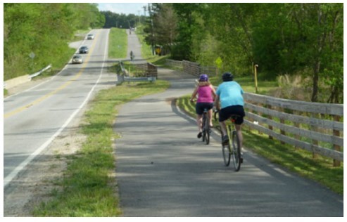
Figure 18-28: Example Photo of Rural Shared Use Path
18.4.8.1 Shared Use Path
A Shared Use Path adjacent to roadway (sidepath) with separation from the roadway is an option on rural facilities. An additional option is a Shared Use Path on an independent alignment. While it is recognized that these types of facilities are not usually feasible on most rural projects, consideration should be given to using them on the
Texas Bicycle Tourism Trails Example Network
and rural roadways with ADT over 6000. If they are used, see
and the
for further design guidance.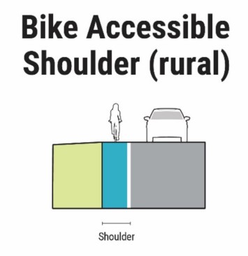
Figure 18-29: Example Rural Bike Accessible Shoulder Schematic
18.4.8.2 Bike Accessible Shoulders
Bike accessible shoulders in rural areas function the same as bike accessible shoulders in urban areas with the exception that the roadway will generally not have curb at the edge. If they are used, see
, and the
for further design guidance.
18.4.8.3 Shared Lanes (wide outside lanes)
Shared lanes (wide outside lane) are lanes that allow compatibility of operation for both motorized vehicles and bicycles. Since bicycles may be operated on all roadways except where prohibited by statute or regulations, shared lanes without markings already exist in many rural settings.
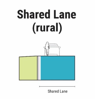
Figure 18-30: Example Rural Shared Lane Schematic
Note that although marked shared lanes are allowed in the
for certain conditions, TxDOT as a general policy does not recommend marked shared lanes for TxDOT roadways due to the higher speed nature of TxDOT roadways as compared to local jurisdictions. Also, shared lane markings alone do not provide any additional safety for bicyclists and do not substantiate a dedicated bicycle facility. In a rural applications, shared wide outside lanes should only be used in locations with low volumes (1,000 ADT or lower) and speeds of 45 mph or less.