18.5 Intersections and Crossings
The design of bikeways at intersections will come in many configurations as they are natural locations to transition between bikeway types and to respond to conditions where bikeways are discontinued. Each intersection is unique and requires engineering judgment to determine an appropriate design to maximize safety. The following guidance provides examples for how to transition bikeways at intersections for common conditions Due to the mixed nature of traffic at intersections (pedestrians, bicyclists, and motorists), the designer should keep in mind the speed of each travel mode and its resulting effect on design values when considering design treatments. The fastest vehicle should be considered for approach speeds (typically the bicyclist and motor vehicle) because these modes require the greatest stopping distance. By contrast, for departures from a stopped condition, the characteristics of slower users (typically pedestrians and bicyclists) should be considered due to their greater exposure to cross traffic.
A bicycle crossing is any location where a bicyclist enters and crosses a roadway from one dedicated bikeway to another. Bikeway crossings of roads can be broadly categorized as mid-block, intersection, or grade separated.
Intersection crossings occur within the functional area of an intersection of two or more roadways (see
). Intersection crossings for bicyclists are typically parallel to at least one roadway and have unique operational challenges. Geometric design guidance for intersections should also be applied to driveway crossings and alley crossings to promote safety and visibility for bicyclists and pedestrians. Mid-block crossings are those located outside of the functional area of any adjacent roadway intersection. Grade-separated crossings pass over or under a roadway and eliminate conflicts between bicyclists and motorists.
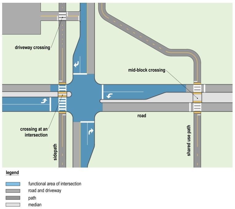
Figure 18-31: Crossing Locations Relative to Intersections Functional Area
(Refer to the
and
for additional signing and pavement marking guidance.)
18.5.1 Principles of Intersection Design
18.5.1.1 Minimize exposure to conflicts
Intersections with bikeways should be designed to minimize bicyclist exposure to motorized traffic and minimize bicyclist conflicts with both motorists and pedestrians. Exposure to conflicts can be eliminated with:
- Geometric design treatments;
- Restricting turn movements;
- Providing traffic signal phasing that manages conflicts; or
- Providing grade separation where appropriate.
Where elimination of conflicts is not possible or practical, intersection designs should limit the amount of time and space where bicyclists are exposed to moving or crossing traffic in locations where:
- Bicyclists cross multiple vehicular travel lanes;
- Bicyclists operate between moving vehicular travel lanes;
- Bicyclists wait in areas exposed to moving motor vehicle traffic (e.g., waiting to turn left in a shared lane);
- Motorists merge with, or turn across the path of, bicyclists; and
- Bicyclists cross pedestrian travel paths or other bikeways.
A primary concern for safety and comfort on facilities where bicyclists and pedestrians operating in shared space is the relatively higher speeds bicyclist operate compared to pedestrians. To mitigate crash risk between bicyclists and pedestrians and improve comfort for both users it is important to:
- Provide clear sight distance between pedestrians and approaching bicyclists at locations where bicyclists cross a pedestrian facility (see );
- Provide facilities with widths which can accommodate the volume of users; or
- Separate bicyclists from pedestrians.
18.5.1.2 Reduce speeds at conflict points
If conflict points cannot be eliminated, intersection design should minimize the speed differential between users at the points where travel movements intersect by reducing motorist speeds at these locations. Intersections where bicyclists operate should be designed to ensure slow speed motorist turning movements (10 mph or less) and weaving movements (20 mph or less) across the path of bicyclists.
18.5.1.3 Communicate right of way priority
Intersection design should provide bicyclists, pedestrians, and motorists with cues that both clearly establish which user(s) have the right of way and consistently communicate expected stopping or yielding behavior.
Traffic control devices should communicate the priority right of way through the provision of:
- Marked crosswalks at shared use path crossings;
- Marked bicycle crossings of roadways and driveways;
- Audible and vibrotactile devices for people with disabilities at crossings of bikeways where appropriate;
- Marked pedestrian crossings of bikeways;
- Regulatory or warning signs for crossing, merging, or turning traffic where appropriate; and
- Signalization where appropriate
18.5.1.4 Provide adequate sight distance
It is necessary to provide adequate sight distances and visibility between bicyclists, motorists, and pedestrians as they approach intersections. Adequate sight distance is needed to perceive, react to, and avoid potential conflicts. See
for more details.
18.5.1.5 Provide clear transition between bikeway types
Intersections are likely to be locations where bicyclists transition between different types of bikeways. These transitions should be intuitive to all users of the intersection. Transitions from off-street bikeways to on-street facilities should be clearly communicated with advance warning signs to bicyclists and in some instances, motorists where bicyclists entering the roadway may be unexpected. Advance warning signs or pavement markings should be considered at locations where a bikeway may unexpectedly narrow at a transition. Transitions can also benefit from the provision of wayfinding to guide users along the preferred path of travel. It is also important to provide clear and direct paths for pedestrians across bikeways. Protected intersection designs may reduce the likelihood that pedestrians will use a bike lane as a walkway. See
for more details.
18.5.1.6 Accommodate people with disabilities
Intersections must be designed in accordance with accessibility guidelines. Designs should ensure that people with limited or no vision are given sufficient cues to prevent them from unintentionally moving into the street or a bike-only bikeway. See
and other general information in the pedestrian guidance.
18.5.2 Intersection Approach Treatments
Managing potential conflicts with merging or crossing motor vehicle traffic is a fundamental challenge for bicyclists operating within bikeways at intersections. As a bikeway approaches an intersection, designers should aim to provide a continuous and direct route through the intersection, driveway, or alley that is recognizable to all users of the roadway. Designers should also aim to minimize or eliminate conflict areas and to maintain bikeway continuity up to and through an intersection, as intersections can be the most stressful locations for bicyclists to navigate.
Constrained environments may occur at intersections where additional motorist capacity is needed to accommodate turn lanes. Designers have several options when balancing bikeway designs with the need to accommodate turning traffic. Given the operational reality that bicyclists are operating on the right-side of the roadway as a slower, vulnerable roadway user, a key design influence is the interaction of bicyclists with right turning traffic and the geometric design of the intersection where this interaction occurs. The design of the intersection approach is influenced significantly by the bikeway design on the approach and departure of the intersection.
The following guidance covers the most common transition scenarios. For all scenarios described in this section, a high-comfort optional bicycle ramp to a sidewalk or protected intersection (see
) should be considered where the bikeway selection guidance in
indicates a need for additional separation and the existing condition is a shared lane, shoulder, or bicycle lane.
The following treatments are not presented in order of priority. The bikeway selection guidance of
should be used when evaluating intersection treatments in addition to the principals of
. It is preferable to provide the same level of accommodation as mid-block sections of a roadway.
18.5.2.1 Shoulder or Bicycle Lane Terminated to a Shared Through Lane
shows an intersection where a shoulder or bicycle lane is terminated because the roadway narrows or the lane becomes an additional through travel lane. The bicycle lane or shoulder should be dotted between 50 and 200-ft prior to the point where it ends to clarify this is a location where bicyclist must either merge into the traffic lane or where a bicycle ramp is provided with the option to exit to a sidewalk, separated bike lane, or sidepath. A BICYCLE warning sign (W11-1) or BICYCLES MERGE sign may be considered at the start of the dotted lane line followed by a BICYCLES ON ROADWAY or BIKES MAY USE FULL LANE sign. At locations with bicycle lanes, a BICYCLE LANE ENDS sign may be posted in lieu of a BICYCLES MERGING sign.
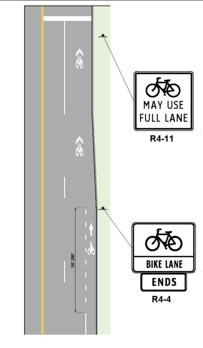
Figure 18-32: Example Shoulder or Bike Lane Terminating to a Shared Through Lane
(Refer to the
and
for additional signing and pavement marking guidance.)
18.5.2.2 Shoulder or Bicycle Lane Terminated to a Shared Right Turn Lane
Where there is insufficient space for a bike lane and a right turn only lane, designers must assess the risk to bicyclists when considering which of the following is a preferred option based on operational conditions at the location:
- Bike lane transitions to a shared right-turn lane ( );
- Bike lane transitions to a shared through lane ( );
- Bike lane transitions to a protected intersection ( ) or sidewalk via a bike ramp.
Shared lane markings may be located within the left side of the turn lane (
) if the lane is a minimum 14-ft, otherwise the shared lane markings should be located within the center of the right turn lane or located within the adjacent through travel lane (
) following
guidance. At locations where the lane is 15 or more feet in width, provision of a bicycle lane should be considered.
Designers should consider the volumes for each movement, the queuing length, time spent queuing, and operational speeds when determining if bicyclists should be placed in the through or right-turn lane.
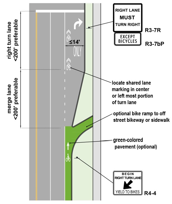
Figure 18-33: Example Bike Lane Transitions to a Shared Lane Markings in Right Lane
(Refer to the
and
for additional signing and pavement marking guidance.)
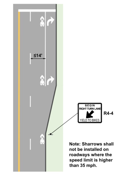
Figure 18-34: Example Bike Lane Transitions to a Shared Lane Markings in Through Lane
(Refer to the
and for
additional signing and pavement marking guidance.)
18.5.2.3 Shoulders and Bicycle Lanes Continue with Addition of Right Turn Lanes
shows an intersection where a through travel lane becomes a right turn only lane. In this scenario, the bike lane should shift to the left of the turn lane. The bike lane should remain along the curb until it is within 400-ft of the intersection. The bike lane drops at this point and is re-introduced on the left side of the right turn lane within 200-ft of the intersection.
In this scenario, the bike lane should not be striped diagonally across the travel lane, as this inappropriately suggests to bicyclists that they do not need to yield to motorists when moving laterally. Where operating speeds are less than 30 mph, shared lane markings may be used to delineate the likely path of travel of bicyclists transitioning across the shared lane between the bike lanes. A BICYCLE warning sign (W11-1) or BICYCLES MERGE sign should be placed where the curb side bike lane ends.
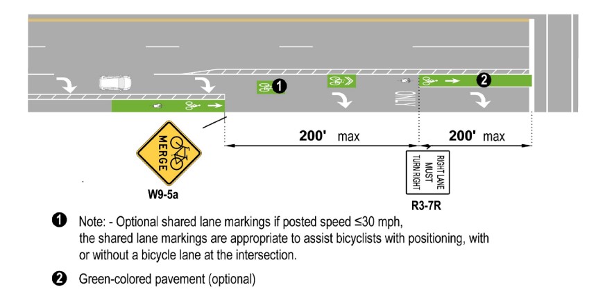
Figure 18-35: Bike Lane Transitions to Through Bike Lane with Right Turn Lane
(Refer to the
and
for additional signing and pavement marking guidance.)
shows an intersection that transitions a bike lane to a separated bike lane on the right side of right-turning vehicles. This may be desirable at locations where there are more than 150 right turning vehicles during the peak hour or an existing crash history. Signal phase separation of bicyclists and motorists should be considered with a bicycle signal. In this scenario, it is preferable the separated bike lane provide:
- A 6-ft bike lane width desirable exclusive of a gutter, 4-ft minimum; and
- A 6-ft buffer width desirable, 2-ft minimum.
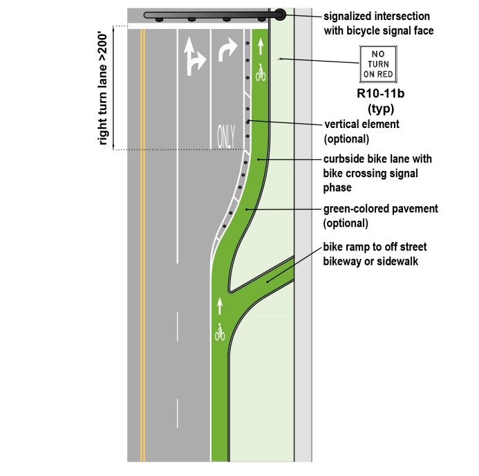
Figure 18-36: Example Bike Lane Approach to a Right Turn Only Lane
(Refer to the
and
for additional signing and pavement marking guidance.)
shows a right turn lane which requires drivers to physically cross the bike lane within a constricted area formed by vertical elements, such as medians or flexible delineators to force motorists to enter the turn lane at a clearly defined location, thus providing a more predictable conflict point. The opening must be designed to accommodate the desired motorist operating speed. A target speed of 35mph or less is preferred for the use of this design.
In this scenario it is preferable the separated bike lane provide:
- A 6-ft bike lane width desirable, 4-ft minimum; and
- A 2-ft minimum buffer width is required; otherwise provide maximized width bike lane ( ).
provides additional design options to accommodate bike lanes as they approach an intersection.
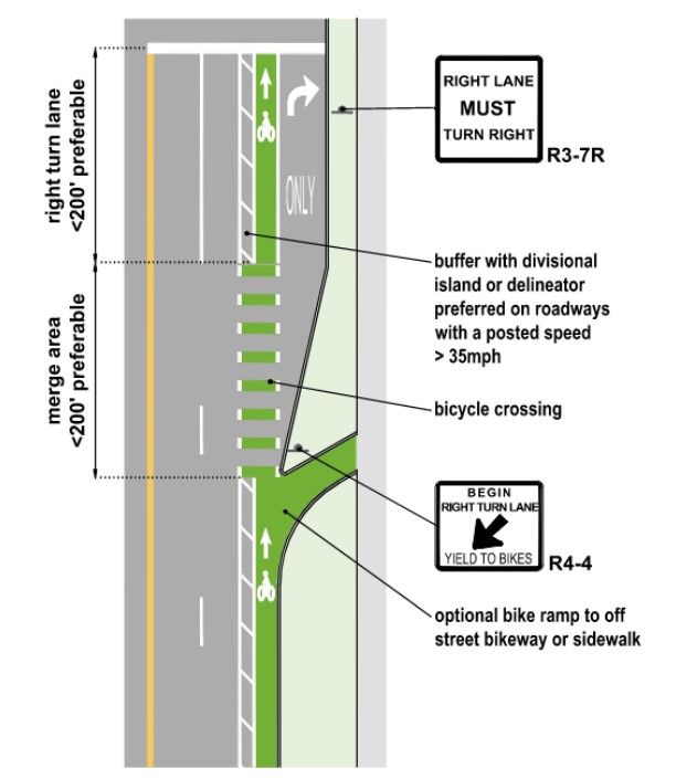
Figure 18-37: Bicycle Lane with Constricted Motorist Entry Point
(Refer to the
and
for additional signing and pavement marking guidance.)
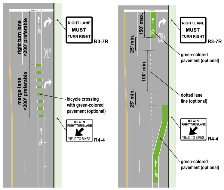
Figure 18-38: Standard Bicycle Lane with Right Turn Lane
(Refer to the
and
for additional signing and pavement marking guidance.)
18.5.2.4 Shoulder Transition to Bicycle Lane
Designers can transition a shoulder to a bicycle lane prior to intersections where it is desired to emphasize bicyclists have the ROW at the intersection as through moving vehicles, and then transition back to a paved shoulder on the far side of the intersection (
). Transitioning a paved shoulder to a bicycle lane at intersections may be desirable at locations near high-speed exit and entrance ramps (greater than 35 mph) where shoulders are the predominant bicycle accommodation in the area
Where shoulders are a part of a bike route, the striping should not taper towards the cross street at intersections, but it should transition to a dotted edge line where motorists are expected to use the shoulder to begin their turning movement (see
). The right edge of the shoulder for the turning roadway can be marked with a solid white line where delineating this edge is important for safety reasons
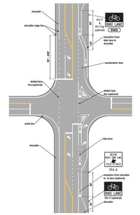
Figure 18-39: Example Shoulder Markings to Accommodate Bicycling
(Refer to the
and
for additional signing and pavement marking guidance.)
18.5.2.5 Shoulder Transition to Bicycle Lane at T-Intersections with Bypass Lanes
Bypass lanes at T‐intersections of two-lane roadways can be designed to facilitate the passing of motorists stopped to make left turns onto intersecting roads without encroaching into a bicyclists operating space (
). Where this is done on a roadway with paved shoulders, at least 4-ft of usable shoulder pavement clear of rumble strips should be carried through the intersection along the outside of the bypass lane and designated as a bike lane. At locations where guardrails are present, an additional 2-ft of shoulder width is recommended. This is especially critical on roadways with higher volumes and operating speeds where bicyclists operating on the shoulder are likely to be in conflict with traffic using the bypass lanes.
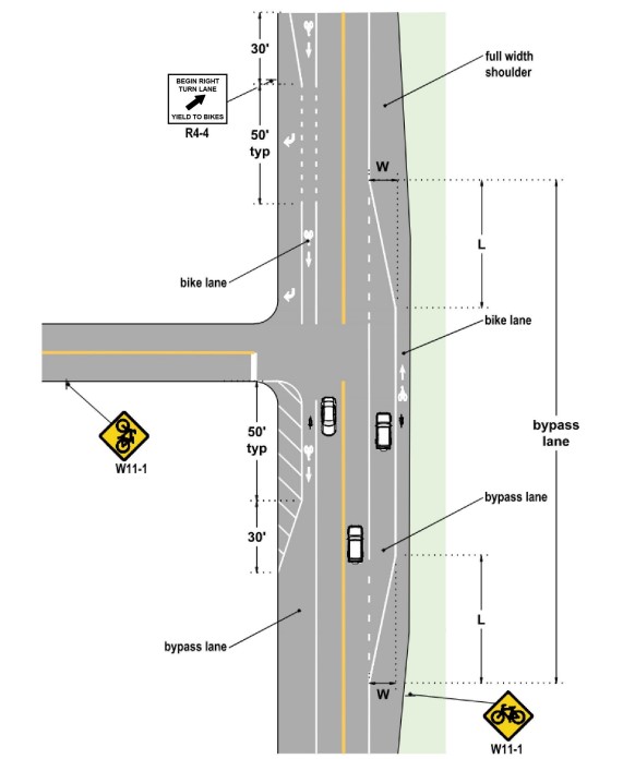
Figure 18-40: Motorist Bypass Lane with Bicycle Lane
(Refer to the
and
for additional signing and pavement marking guidance.)
18.5.2.6 Protected Intersection or Continuation of Separated Bike Lane or Sidepath
Protected intersections result from the application of a separated bike lane or sidepath up to the intersection (
). They may also be developed by transitioning a shared lane, shoulder, or bicycle lane into a separated bike lane or sidepath in advance of an intersection. They may be used at signalized and unsignalized intersections and driveways.
The defining features of protected intersections are a recessed bicyclist crossing and intersection corner geometry designed to slow right turning motorist speeds to improve motorist stopping or yielding to through moving bicyclists and parallel crossing pedestrians. Designers should aim to create an offset between the adjacent vehicle lane and the bike crossing between 6-ft and 16.5-ft from the adjacent motor vehicle lane. This treatment has been shown to significantly reduce crashes at uncontrolled and permissive conflict locations.
Additional guidance on protected intersections may be found at:
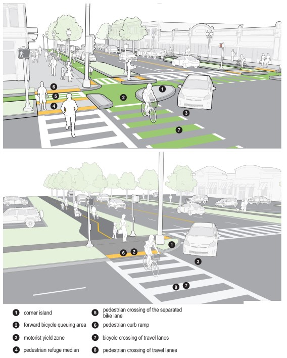
Figure 18-41: Protected Corner Treatment and Intersection Design Components
(Refer to the
and
for additional signing and pavement marking guidance.)
18.5.2.6.1 Corner Island
A key component of a protected intersection is the corner island, which provides the following benefits:
- Is used as a design control to set the horizontal offset between the adjacent motor vehicle lane and the bike crossing, to create a motorist stop or yield zone;
- Is used as a design control to slow turning vehicles to a desired turning speed in combination with truck aprons where necessary;
- Positions bicyclists waiting to cross in front of adjacent stopped motorists improving their visibility to motorists;
- Creates queuing space for bicyclists making a two-stage turn, outside of the path of through bicyclists; and
- Allows for a pedestrian refuge island, shortening their crossing and reducing exposure.
A corner island is a raised island between the bike lane and travel lane that defines the motorist’s turning radius and slows their turning speed. They are typically constructed using concrete and curbing. The corner island should be constructed with a standard vertical curb to discourage and prevent motor vehicle encroachment. In retrofit projects, they may be constructed with low-cost materials, such as paint and flexible delineator posts or engineered rubber curbs and/or rubber speed cushions.
shows details for corner islands in a protected intersection.
When on-street parking is located along the corridor, parking restrictions at intersection approaches will provide space for a street buffer to install a corner island. When there is no parking along the corridor, the bike lane can be offset away from the travel lane to create space for the desired corner island and motorist stop or yield zone. The corner island geometry will also impact the size of the motorist stop or yield zone and can be designed to slow approaching bicyclists’ speeds at the point of potential conflict by requiring some deflection of the bicyclists’ travel path. That deflection should generally not exceed the width of the bicycle lane.
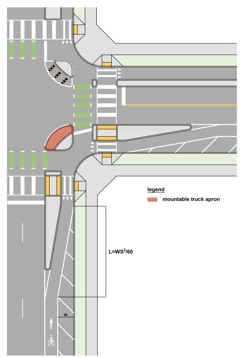
Figure 18-42: Protected Intersection Treatments with Truck Apron
(Refer to the
and
for additional signing and pavement marking guidance.)
18.5.2.6.2 Truck Aprons
A truck apron is a design feature of some corner islands and is designed to accommodate the turning needs of large vehicles while slowing the turning speeds of smaller vehicles. The truck apron portion of the corner island is designed to be mountable by larger vehicles (the design vehicle) to accommodate their larger effective turning radius. The outside edge of the truck apron is constructed with a mountable curb (i.e., the interface between the pavement and truck apron) and should be designed for a passenger (P) or delivery vehicle (SU-30), to turn outside the apron at a slower speed.
below shows the larger vehicle’s effective turning radius traversing the truck apron and the passenger vehicle’s actual radius at the edge of the truck apron, noting that the bicycle stop bar (a.k.a., stop line) is located behind the larger vehicle turning path.
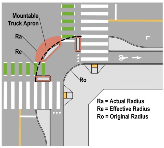
Figure 18-43: Actual vs Effective Radius
(Refer to the
and
for additional signing and pavement marking guidance.)
18.5.2.6.3 Pedestrian Considerations
When the street buffer is at least 6-ft in width, it may be used as a pedestrian refuge island, which shortens the crossing distance. In this case, pedestrians would cross the separated bike lane at an uncontrolled crossing, then cross the motor vehicle lanes as a separate crossing. When the crossing is located at a signalized intersection, the designer can consider reducing the signal timing for the pedestrian crossing to reflect this shorter crossing distance if the push buttons are located within the pedestrian refuge median. Stop bar markings (and associated R1-5b sign) and crosswalk markings should indicate the right of way between bicyclists and pedestrians at these locations.
below details various protected corner treatment methods.
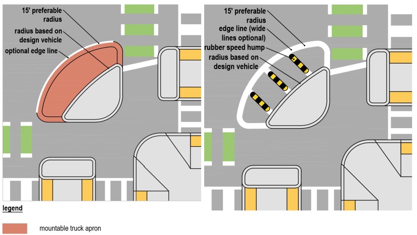
Figure 18-44: Protected Corner Treatment Details: Truck Apron (left) and Turning Wedge (right)
(Refer to the
and
for additional signing and pavement marking guidance.)
18.5.2.6.4 Traffic Control Considerations
At all intersections, the designer should consider using a TURNING VEHICLES YIELD TO PEDESTRIANS AND BICYCLES (R10-15) sign to communicate where turning motorists need to stop and yield to these street users. Use of a modified sign similar to the TURNING VEHICLES STOP FOR PEDESTRIANS (R10-15a) sign with a bicycle symbol may be considered.
In scenarios where a separated bike lane approaches an intersection that does not have adequate space for a protected intersection, the separated bike lane will have to transition to a bike lane or shoulder in advance of the intersection with a bicycle ramp.
18.5.2.7 Transitions from Protected Intersection to Other Bicycle Facility Types
When a protected intersection is provided for any bikeway type, the preference is for that protection to continue through the intersection and for the transition to a bikeway with less separation to occur on the far side of the intersection as shown below with the exception of sidepath transitions which require special considerations for pedestrians.
18.5.2.7.1 Transition from Separated Bike Lane to Shared Lane
It is preferable for the transition into a shared lane to occur after crossing a roadway to allow bicyclists time to stop and ascertain when it is safe to enter the roadway without conflict from approaching motorists who may be turning from the crossed roadway or approaching from the main roadway (
). Where this is not an option, the transition on the approach to the intersection should be in advance of the stop line on the roadway.
This location should ensure a clear sight line between all approaching motorists and the bicyclist. It may be desirable to add a BICYCLES MAY USE FULL LANE (R4-11) sign at the location where the bicyclist enter the roadway. A yield sign may be considered at the point where the bicyclists enters the roadway.
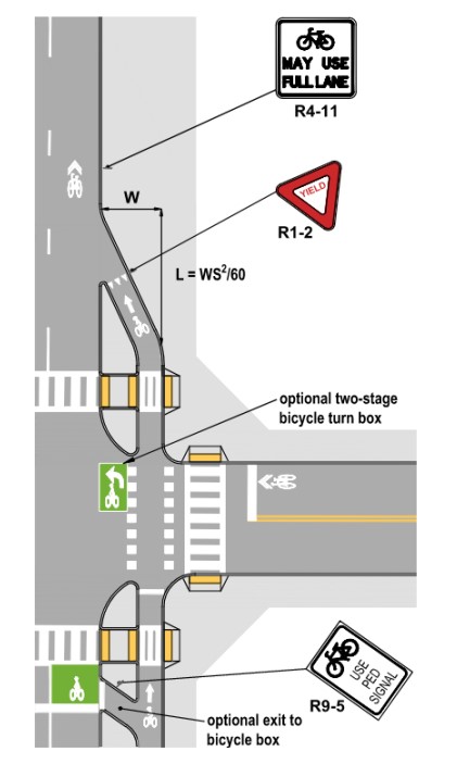
Figure 18-45: Transition to Shared Lane
(Refer to the
and
for additional signing and pavement marking guidance.)
18.5.2.7.2 Farside Transition from Separated Bike Lane to Bicycle Lane or Shoulder
The transition into a bicycle lane on the far side of the crossing may occur at any point after the bicyclist crosses the pedestrian crossing (
). This will minimize the pedestrian crossing of the roadway.
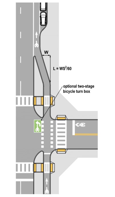
Figure 18-46: Transition to Bike Lane
(Refer to the
and
for additional signing and pavement marking guidance.)
18.5.2.7.3 Transitions from Two-Way Separated Bike Lanes to One-Way Separated Bike Lanes
Transitions of two-way separated bikeways into bikeways with one-way operation require additional considerations. Bicyclists operating in the contraflow direction will be required to cross at least two directions of travel and failure to provide a clear transition to the desired location may result in wrong way bicycle riding as shown in
and
. The crossing may warrant bicycle signals at signalized crossings (see
). The use of directional, tapered islands can provide positive direction for bicyclists to follow the desired transition route. It may also be desirable to use green-colored pavement within crossings and two-stage bicycle turn boxes to improve legibility and provide strong visual guidance of the intended path across the intersection to all users. The crossing may warrant bicycle signals at signalized crossings. The signal should be coordinated with the intersecting street signal phase.
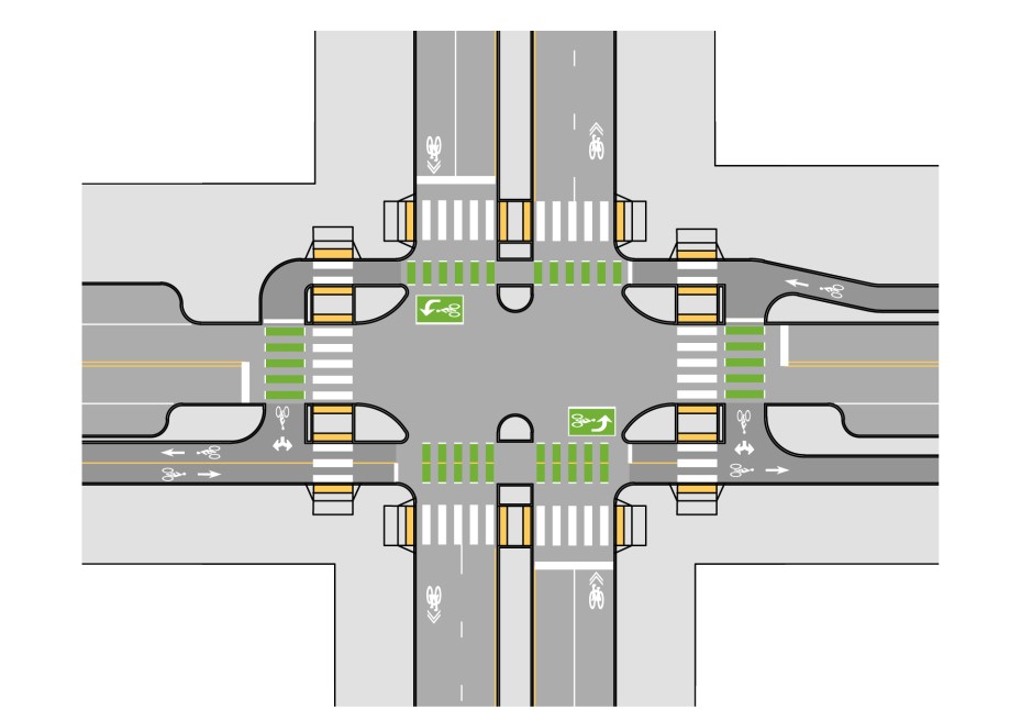
Figure 18-47: Transition from One-Way to Two-Way Separated Bike Lanes with Protected Intersection
(Refer to the
and
for additional signing and pavement marking guidance.)
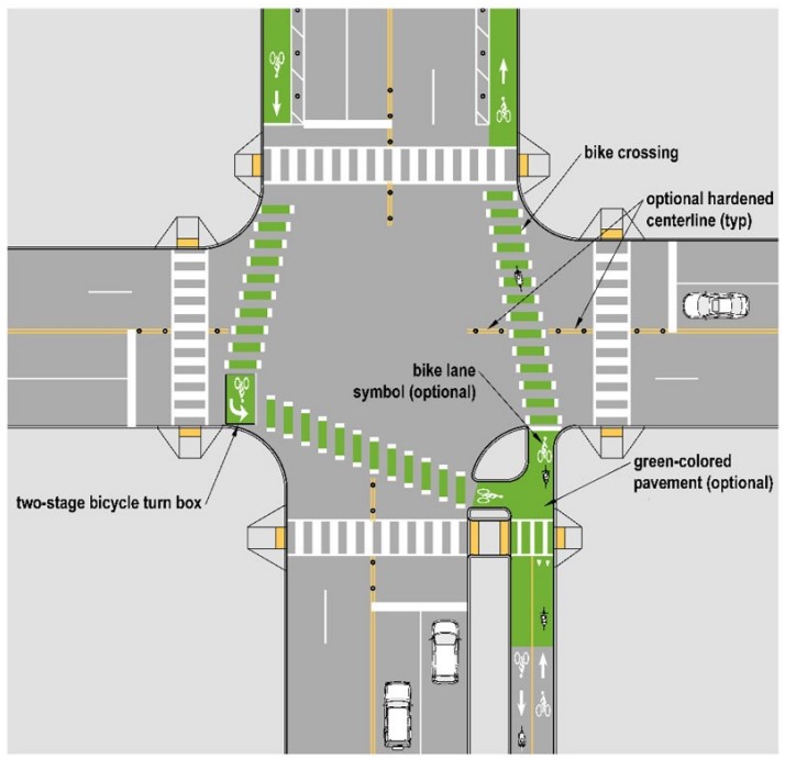
Figure 18-48: Transition from One-Way to Two-Way Separated Bike Lanes with Protected Corner and Two-Stage Turn Queue Box
(Refer to the
and
for additional signing and pavement marking guidance.)
18.5.2.8 Raised Bike Lane Considerations at Intersections
At locations where bike lanes are raised and located adjacent to a travel lane, the raised bike lane must transition to street level into a bike lane or shared lane, or it must bend away from the travel lane into a sidewalk, sidepath, or separated bike lane (see
). It is preferable to transition the raised bike lane to bend away from the travel lane to form a protected intersection which minimizes conflicts with turning motorists. From the point where the bicycle lane shifts to become a separated bike lane, the design should follow the Protected Intersection Guidance in
(Option 1).
Where protected intersections are not feasible, the raised bike lane should transition to street level. At intersections with low volumes of right turning traffic (less than 50 per hour) or locations where a phase separated right turn lane is provided, it is preferable for the raised bike lane to continue to the intersection and return to street level on a ramp within 10-ft to 30-ft of a pedestrian crosswalk (Option 2).
Where it is determined to transition the raised bike lane to a right turn lane, standard bike lane or shared lane, that transition should occur between 50-ft to 200-ft prior to the intersection (Option 3). At locations with higher volumes of right turning traffic, a bike ramp should be considered to allow bicyclists to transition to the adjacent sidewalk or sidepath.
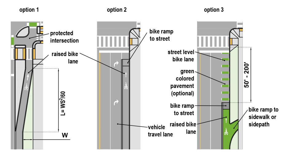
Figure 18-49: Raised Bike Lanes at Intersections
(Refer to the
and
for additional signing and pavement marking guidance.)
18.5.3 Bicycle Ramps to Transition Between Bicycle Facilities
18.5.3 Bicycle Ramps to Transition Between Bicycle Facilities
Bicycle ramps can be used to transition bicyclists between on road bicycle facilities (shared lanes, bicycle lanes, and shoulders) to off road facilities (separated bike lanes, sidewalks, and sidepaths) as discussed in previous guidance. Bike ramps have commonly been used on the approaches to interchange ramps, areas with heavy weaving or merging, intersections with high turning volumes, or the approaches to and departures from roundabouts.
It is preferable to design bike ramp transitions to occur with a gradual taper as depicted in Detail 1 of
following the guidance of
. This is more feasible at locations with a wider buffer with a ramp width of 6-ft to 8-ft recommended.
In constrained conditions, where a buffer is narrower, a more abrupt shift as depicted in Detail 2 of
may be considered or a parallel ramp may be necessary where a buffer is non-existent (Detail 3). These constrained bike ramps can present the following challenges:
- Narrow bike ramp widths less than 8 ft in width with abrupt approach angles can force bicyclist to encroach on adjacent motorist travel lanes, pedestrian zones, or on-coming bicycle traffic on two-way facilities in order to navigate the ramp; and
- If grade breaks at the top and bottom of the bike ramp are not perpendicular to the bicyclist path of travel, bicyclists with more than two wheels (i.e., adult tricycles, bikes with trailers, etc.) can experience instability or overturning and will need to slow significantly to navigate the bicycle ramp.
In constrained buffer situations, a minimum ramp width of 8-ft can help to address these issues. However, consideration should be given to the potential for the ramp to appear like a driveway to motorists. Where driver confusion is likely, it may be necessary to add design elements which clarify that the access is only intended for bicyclists. The provision of bicycle lane symbols, buffers, or green colored pavement may be considered. Where hardened restrictions are necessary, the guidance for restricting motorist access onto shared use paths in
should be followed.
Bike ramps are intended for the exclusive use of bicyclists and therefore need not comply with pedestrian accessibility guidelines but grades similar to pedestrian curb ramps can help to address issues of bicyclist comfort.
Where the bike ramp connects directly to a sidewalk or shared use path, a detectable warning surface, a directional indicator surface, or both may be used at the top of the bike ramp to warn pedestrians and/or guide pedestrians away from the ramp as shown in
.
A directional indicator is a tactile surface comprised of raised bars detectable underfoot and with a white cane that may be deployed parallel to the pedestrian path of travel to help pedestrians follow an accessible pathway or navigate a large open space. They may also be deployed across the pedestrian path of travel to provide guidance to pedestrians with disabilities regarding when to turn (e.g., to locate a mid-block curb ramp, bus island, or transit door).
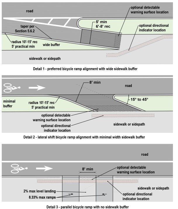
Figure 18-50: Bicycle Ramps
(Refer to the
and
for additional signing and pavement marking guidance.)
18.5.4 Driveways
18.5.4.1 Driveway Crossings of Shoulders and Bicycle Lanes
When on-street shoulders or bicycle lanes cross driveways, their pavement markings should extend through the conflict point as follows:
- Low Volume Driveways (<25 veh/day)- Shoulder and bicycle lane markings should be maintained across driveway with solid white lines. Stop or yield control is optional for the motorists approaching the crossing from private property.
- Medium Volume Driveways (25-500 veh/day)- Bike Crossing Markings should be used (see ); Stop or yield control should be considered for the motorists approaching the crossing from private property.
- High Volume Driveways (>500 veh/day)- Bike Crossing Markings should be used (see ); These driveways may be designed according to the intersection design principles laid out in this chapter. Traffic control should be evaluated with an engineering study.
18.5.4.2 Driveway Crossings of Separated Bicycle Lanes and Sidepaths
For separated bicycle lanes at street level, vertical elements such as flex-posts should be used to control turning motorist speeds into and out of the driveway. They should be placed to define the driveway limits while accommodating the expected turning requirements of the design vehicle. At higher medium to high volume driveways, consideration can be given to developing a raised crossing. See
and
below for details on raised crossings.
For separated bike lanes and sidepaths at sidewalk level, that level should be maintained through the driveway crossing to maintain the raised crossing.
18.5.4.2 Driveway Crossings of Separated Bicycle Lanes and Sidepaths
For separated bicycle lanes at street level, vertical elements such as flex-posts should be used to control turning motorist speeds into and out of the driveway. They should be placed to define the driveway limits while accommodating the expected turning
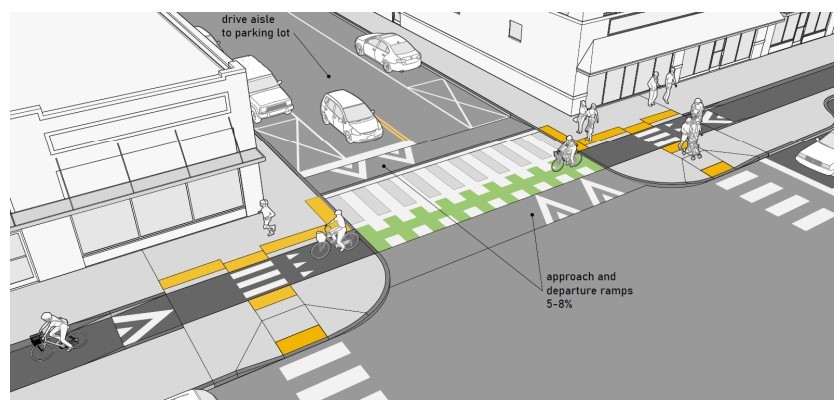
Figure 18-51: Raised Driveway Crossing
(Refer to the
and
for additional signing and pavement marking guidance.)
For all scenarios, adequate sight distances should be provided to ensure motorists exiting the driveway can see oncoming bicyclists and pedestrians and motorists entering the driveway and can see bicyclists and pedestrians approaching the driveway entrance and stop or yield appropriately. On-street parking, especially if it is serving as the vertical element for a separated bike lane, may need to be restricted on either side of the driveway to achieve desired sight lines.
Designers have two options for evaluating the sight distance. They must consider if motorists will take a two-stage approach and be permitted to block a separated bike lane or sidepath to view approaching motor vehicle traffic, or if there is a need for drivers to exit the driveway in a single movement. The single-stage scenario may be appropriate in locations where the motorist would otherwise block the bike facility for extended periods of time or where bicycle volumes or motorist volumes are anticipated to be high.
As discussed previously,
establishes recommended sight triangles that will generally result in sufficient sight distance for bicyclists.
18.5.5 Mid-Block Shared Use Path Crossings
It is preferable for mid-block crossings to intersect the roadway at a 90 degree angle to minimize the crossing distance and maximize sight distance. Mid-block crossings crossings may be controlled (signalized) or uncontrolled (signing and markings only). Designers should consider traffic volumes and speeds of motorists, sight distances, the bicyclist target design user profile, and the walking speed of pedestrians when designing mid-block crossings. This is particularly important for uncontrolled crossings because the crossing users are reliant on motorist stopping and yielding or finding gaps in traffic. The
provides recommendations for appropriate treatments to consider for uncontrolled crossings, which can be used for shared use path crossings. Additionally,
signal warrants may be used (with bicyclists counted as pedestrians) to identify if a full signal is appropriate. The signal warrant should consider the anticipated volumes of pathway users during the peak riding period (which may be on weekends).
through
illustrate various examples of mid-block crossing control treatments. These figures show typical pavement marking and sign crossing treatments. The diagrams are illustrative and are not intended to show all signs and markings that may be necessary or advisable, or all types of design treatments that are possible at these locations. Each figure assumes the appropriate minimum sight distances are provided for the roadway and the shared use path. Refer to the
guide for recommended treatments and countermeasures to address motorist stopping and yielding
Refer to the
for additional guidance for shared use path crossings
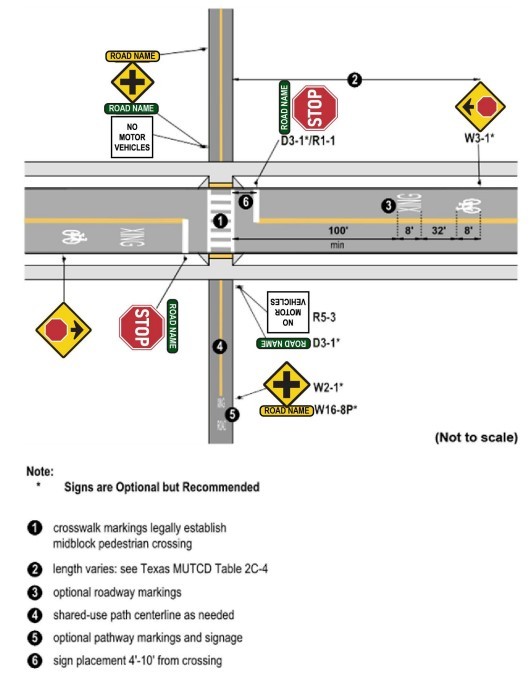
Figure 18-52: Road Stops
(Refer to the
and
for additional signing and pavement marking guidance.)
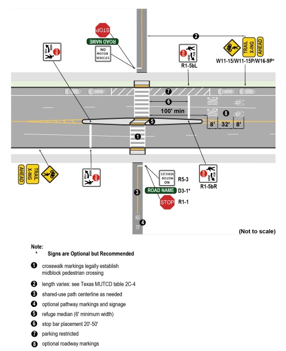
Figure 18-53: Multilane Road Uncontrolled with Advance Stop Bar Line
(Refer to the
and
for additional signing and pavement marking guidance.)
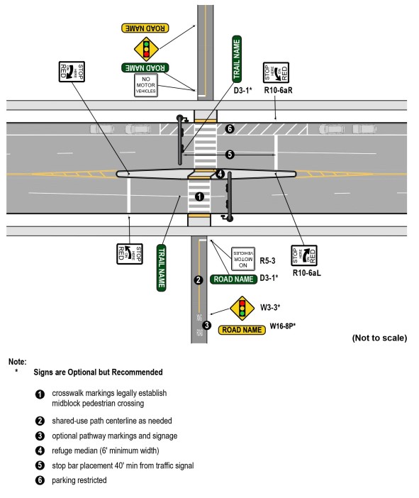
Figure 18-54: Multilane Road with Signals
(Refer to the
and
for additional signing and pavement marking guidance.)
18.5.6 Roundabouts
provides guidance on roundabouts, which provide non-signalized traffic control at intersections with a circulating lane (or lanes) around a central island traveling counterclockwise
While the Highly Confident bicyclist may be comfortable traversing a roundabout in a shared lane environment, many bicyclists will not feel comfortable navigating roundabouts with vehicular traffic, especially multilane roundabouts. Per the
, standard bike lanes are not permitted to be located within the circulatory roadway of a roundabout. For comfort and safety reasons, roundabouts may be designed to facilitate bicycle travel outside of the circular roadway on a separated bike lane or shared use path.
This transition from on-road to separated bikeway should be located a minimum of 100-ft from the edge of the roundabout circulatory roadway (see
and
). If on-street bike lanes are present, they should be terminated in advance of the roundabout at the transition to the separated bikeway. As shown on
, a bicycle ramp should be provided to transition between an on-street bikeway and a raised bikeway, such as a shared use path. Designers should provide an appropriate taper of the bike lane to narrow the entry width for the roundabout to only the motorist travel lanes. The bike lane line should be dotted for 50 to 200-ft in advance of the taper to provide guidance to bicyclists who wish to travel the roundabout in the shared lane.
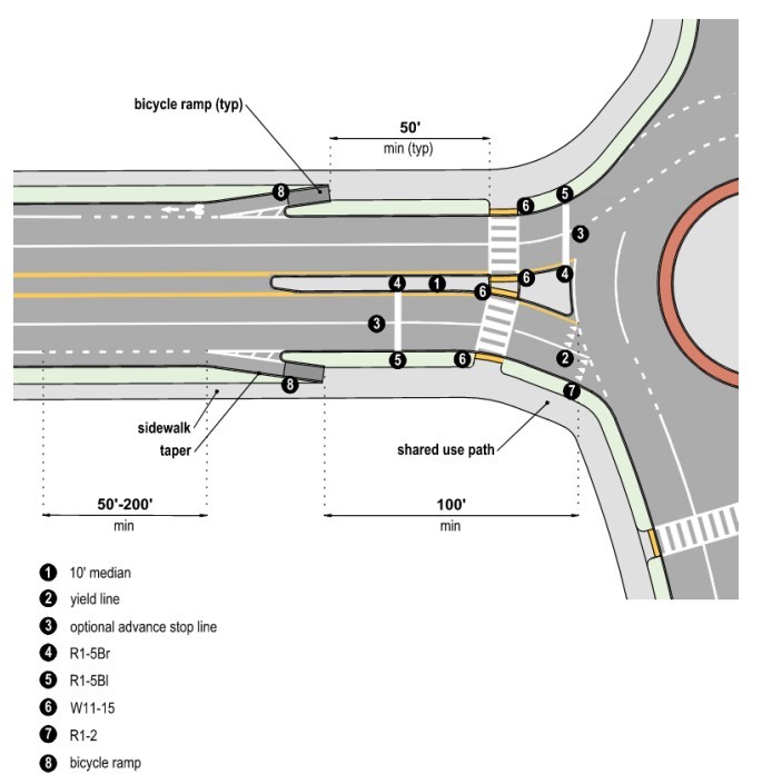
Figure 18-55: Typical Layout of Bike Lane Transitions to Shared Use Path at Multilane Roundabout with Bike Ramps
(Refer to the
and
for additional signing and pavement marking guidance.)
When separated bike lanes are provided on approaches to roundabouts, they may be continued around the intersection by maintaining their separation from the roadway to maintain the continuity of the bikeway. When bike lanes are provided on approaches to roundabouts, and if it is desirable to maintain separation between bicyclists and pedestrians, the bike lanes may transition to separated bike lanes around the roundabout. Standard bicycle lanes are not allowed within roundabouts. Separated bike lanes at roundabout crossings should provide the following features:
- Stop and yield control for motorists at the bicycle and/or pedestrian crossing;
- Channelizing islands or detectable surfaces to maintain separation between bicyclists and pedestrians throughout the crossings;
- BICYCLE/PEDESTRIAN WARNING (W11- 15) signs at the bicycle and pedestrian crossings; and
- STOP HERE FOR PEDESTRIANS AND BICYCLES (R1-5b modified) sign, supplemented with stop bars may be considered for bike crossings at roundabout exits to reinforce motorist stopping and yielding.
Additional signs or pavement markings may be appropriate to reinforce the bicyclist’s and motorist’s responsibility to stop and yield.
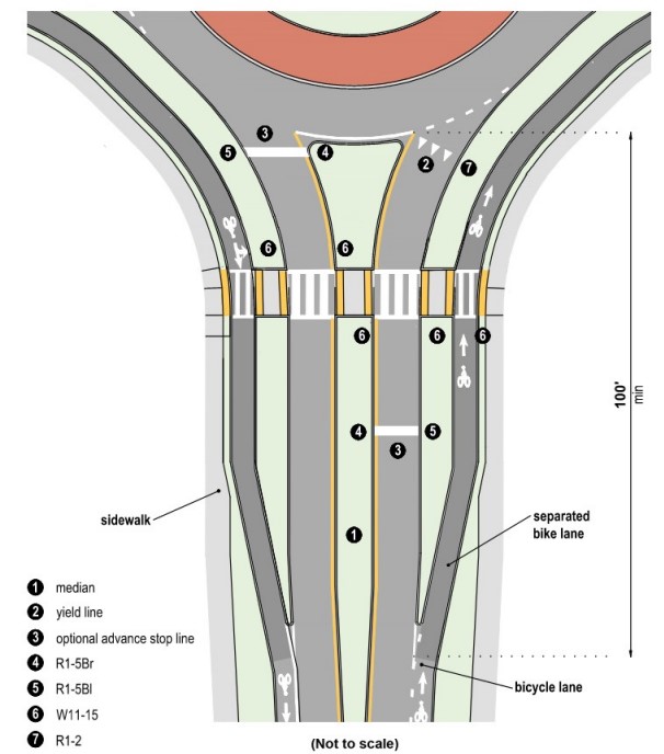
Figure 18-56: Typical Layout of Separated Bike Lanes at Roundabout
(Refer to the
and
for additional signing and pavement marking guidance.)
When shared use paths are provided approaching a roundabout, they should be continuous around the circulating roadway. Shared use path design at roundabouts is similar to separated bike lane design, and should include the following features:
- Minimum shared use path width of 10- ft;
- Widened curb ramps that match the shared use path width at crosswalks to facilitate pedestrians and bicyclists at the crossings;
- Supplemental stop bars for crossings at roundabout exits to reinforce motorist stopping and yielding;
- BICYCLE/PEDESTRIAN WARNING (W11- 15) signs at the shared use path crossings; and
- Bicycle crossing/conflict markings to delineate the bicyclist path of travel may be provided.
At multilane roundabouts at least one of the following additional treatments to alert motorists to the presence of pedestrians or to require them to slow or stop traffic may be required to accommodate people with disabilities at the crossing:
- A raised crosswalk;
- An actuated rapid flashing beacon;
- A pedestrian hybrid beacon; and
- A traffic control signal with pedestrian signal heads.
18.5.7 Railroad Crossings
Railroad tracks that interface with bikeways can be hazardous to bicyclists. The following design considerations are important for bikeways located near tracks:
- Design the bicycle crossing of the tracks to be between 60 degrees and 90 degrees;
- Provide, as practical, the best track surface treatment for bicyclists;
- Provide firm, stable, and slip-resistant pavement;
- Reduce the flangeway width;
- Provide clear delineation with pavement markings that indicates to bicyclists where they should travel to cross railroad tracks at an optimal location;
- Provide warning signs to alert bicyclists of the crossing; and
- Provide adequate sight distances for approaching bicyclists to see the crossing ahead.
Generally, there are two conditions for bikeways and railroad interfaces: tracks located parallel to the bikeway, and tracks located crossing the bikeway.
18.5.7.1 Parallel Tracks
Tracks that are located parallel to a bikeway can be located in the street (e.g., streetcar) or adjacent to the roadway. These tracks are potentially hazardous to bicyclists, both when travelling parallel to the track and when crossing over the track.
While traveling parallel to the track, a bicyclist’s wheel may fall into the flangeway if they travel too close to the track. This may be particularly noteworthy where bikeways are located in the street, in close proximity to rail tracks. In this case, the bikeway should be clearly delineated, and the distance between the bikeway and the track should be maximized.
Bicyclists may need to cross parallel tracks when turning onto or off of the corridor. When turning right, bicyclists should be encouraged (through pavement markings) to cross the track at an angle between 60-degrees and 90- degrees. This reduces the chance of a bicycle wheel falling into the flangeway and a bicyclist slipping on the rail. If tracks are located to the left of the bikeway, bicyclists should be encouraged to use a two-stage turn box to turn left so that they cross the tracks at a 90-degree angle.
shows the design detail of a bikeway crossing parallel tracks.
18.5.7.2 Crossing Tracks
Railroad tracks that cross a street typically cross at an angle near 90-degrees.
shows an example treatment for a bikeway crossing railroad tracks at a skew.
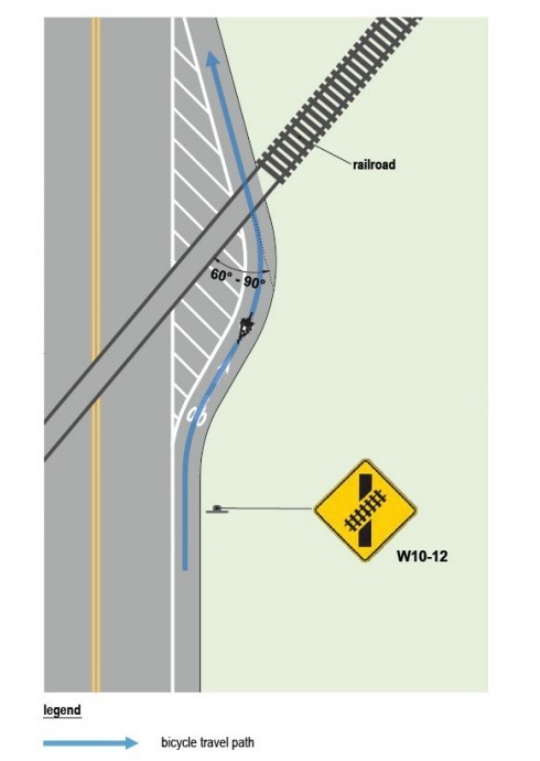
Figure 18-57: Railroad Crossing Example
(Refer to the
and
for additional signing and pavement marking guidance.)