15.8 Frontage Road Turnarounds and Intersection Approaches
Turnaround lanes should be provided at all interchanges with major arterials in urban and suburban areas where the freeway lanes are flanked by one-way frontage roads. Turnaround lanes are not to be provided where two-way frontage roads are used. In urban and suburban areas, overpasses should be arranged so that turnarounds may be added in the future. This includes provisions for end spans and vertical clearance for future turnarounds at overpasses. Underpasses should also allow for vertical clearances on future elevated turnarounds.
When the cross street overpasses the freeway, the resulting turnarounds will be on bridge structures. In these cases, sight lines and distances should be carefully evaluated with respect to any bridge railing sight obstructions. Similarly, sight lines and distances for cross street underpasses must also be evaluated for bridge header and retaining wall obstructions.
The turnaround should be designed to accommodate speeds no more than 15 mph if possible. If lower or higher speeds are justified, a design exception is not required.
shows a typical example of a diamond interchange with frontage roads and turnarounds.
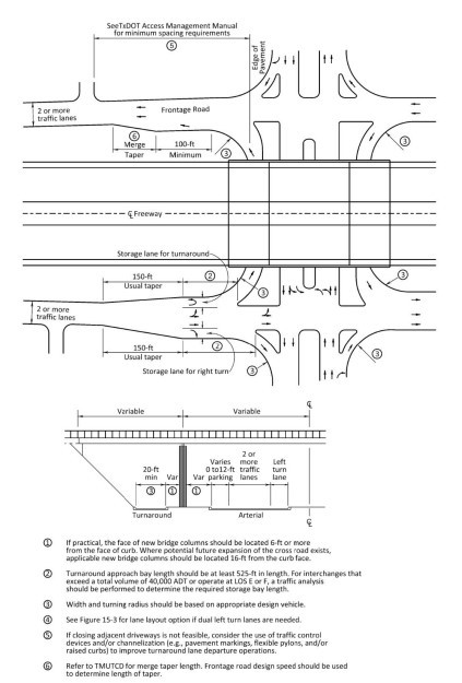
Figure 15-33 Typical Diamond Interchange with Frontage Road
Results from field-based observations, numerous simulations of site improvements with the potential to improve U-turn operations, and a full safety investigation of factors contributing to crashes at interchanges have produced the following guidance on the planning, design, and operation of turnaround lanes:
- Turnaround lanes should be considered for future interchanges with a projected (20-year) peak-hour volume of at least 2,000 vph, or roughly 20,000 ADT. For existing interchanges, turnaround lane implementation should be considered when total interchange traffic volume reaches 4,000 vph, or approximately 40,000 ADT.
- Turnaround lane design should include an approach bay with a minimum length of 525 ft. In rural areas, this length primarily provides stopping sight distance on the U-turn approach for higher-speed operations. In urban areas, the bay length requirement is designed to allow U-turning vehicles to avoid interference from left-turn queues in the adjacent lane.
- Operations are improved if the turnaround lane departure features either a full added lane or an acceleration lane (minimum 100-ft length) with taper. Turnaround lane departures featuring stop or yield control, or those that terminate with only a taper transition into a frontage road lane, should only be used where geometric constraints or low-volume conditions exist.
- To minimize delay and queuing in the turnaround lane and to minimize the potential for crashes on the frontage road, consider closing driveways within the distances referred to in TxDOT’s .
- If closing adjacent driveways is not feasible, consider the use of traffic control devices and/or channelization (e.g., pavement markings, flexible delineators, and/or raised curbs) to improve turnaround lane departure operations. Field observation and simulation studies have verified the benefits (e.g., reduced delay and fewer crashes) of constraining weaving maneuvers from turnaround lanes to adjacent downstream driveways.
- Consider right-turn accommodations at the interchange and their impacts on operations and safety. Safety improvements have been observed when right turns are made from the through right lanes (i.e., no dedicated right turn lanes) and without acceleration lanes.
- Signal timing can be used as an interchange management tool to support U-turn operation. Both cycle length and split adjustments have been successfully demonstrated to reduce frontage road queue length and average delay on frontage road approaches. Shorter queue lengths reduce the likelihood of a left-turn queue blocking access to a turnaround lane.
- Consider the use of dotted line markings to improve interchange operations. Dotted lines to extend lane lines into the intersection and guide drivers through the appropriate turning path have shown reduced delay for turnaround lane movements under medium- to high-volume interchange operations. Directing cross street left-turn vehicles to the middle and/or right frontage road lanes provides gaps in the frontage road for vehicles using the turnaround lane.
See
for discussion on the design of bikeways in intersections. Additionally, refer to
for additional information.
15.8.1 Guidelines for Designing Auxiliary Lanes (AL) on Frontage Roads Approaching Intersections
An auxiliary lane (AL) is a type of roadway lane that is built alongside of and typically adjoining to a roadway’s primary lanes for a limited distance that varies depending on site needs and conditions. ALs are typically built to provide additional roadway capacity and help facilitate safe traffic movements such as speed changes and weaving, merging and diverging, entering and exiting, and turning. ALs are used on freeway frontage roads at and between ramp terminals and at intersections of the frontage roads with crossing roadways. They help balance the traffic load and provide transitions, vehicle storage, acceleration/deceleration to and from driveways/cross-streets, turnaround lanes, and interchange approaches and departures.
See
for additional information regarding auxiliary lanes.
15.8.1.1 AL Merge Length
The minimum length of a frontage road merging AL should be 550’,
not including the taper
. Where design (future year) volumes are expected to exceed 1,000 vph per lane or heavy vehicles are expected to exceed 10% of frontage traffic, the minimum length should be extended an additional 200’, for a total AL length of 750’.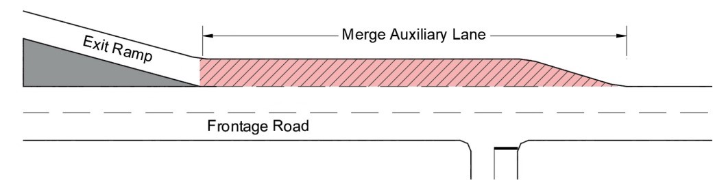
Figure 15-34 Example of a Merge Auxiliary Lane on a Frontage Road
15.8.1.2 X-Ramp Spacing
For X-Ramp configurations, simulation analysis and recent research suggest that the current frontage road minimum weaving section length of 1,000 feet established by the Green Book is applicable only in rural areas and less-developed urban areas without significant current or future frontage road development. However, in urbanizing and urbanized areas with development, the recommended frontage road weaving section length should be 1,500 feet, with a preferred length of 2,000’
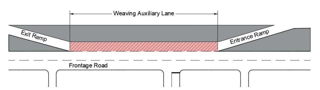
Figure 15-35 Example of a Weaving Auxiliary Lane on a Frontage Road
15.8.1.3 Distance from Exit Ramp to Downstream Intersection:
Fundamentally there are three distinct functional zones between the exit ramp/frontage road merge point and the stop bar for the intersection:
- A storage zone;
- A deceleration zone; and
- And a lane changing or weaving zone.
See
for a visual of these functional zones.
15.8.1.3.1 Queue Storage Zone
Findings confirm that queue lengths of about 180-ft are suitable for rural design and suggest that suburban and urban queue lengths should be even longer than the 420-ft suggested by previous research (
). Queue lengths of at least 700 feet are appropriate for urban signalized intersections.
15.8.1.3.2 Deceleration Zone
The deceleration zone transitions to the storage zone as vehicles slow to a stop behind the longest, reasonably expected intersection queue under design year traffic conditions. Rural frontage roads typically have a higher operating speed than urban locations, so braking distances are greater outside of urbanized areas. See
for additional information on deceleration length.
15.8.1.3.3 Weaving Zone
Through microsimulation and previous research
, the minimum weaving zone for an urban context is 911.8 ft., and 548.2 ft. for rural context as shown in
When designing exit ramps in Texas freeway corridors with diamond interchanges, the minimum recommended spacing between the exit ramp frontage road gore and the downstream intersection is 1,750 ft in urban environments and 925 ft in rural areas. Rural operations improved and stabilized as ramp-to-intersection spacing increased from 500 to 1000 ft, and for urban areas at least 1,500 ft of total ramp-to-intersection spacing was necessary to minimize frontage road travel times/delay.
Context | Assumed Frontage Road Speed (mph) | Weaving Zone Length, Exit Ramp to Right Lane Change(s) (ft) | Deceleration Zone (ft) | Queue Storage Zone (ft) | Total RamptoInterchange Spacing (ft) |
Urban | 45 | 911.8 (two lane changes) | 117.6 | 700 | 1,750 |
Rural | 55 | 548.2 (one lane change) | 194.4 | 180 | 925 |
Figure 15-36: Comparison between Urban and Rural Weaving Zones
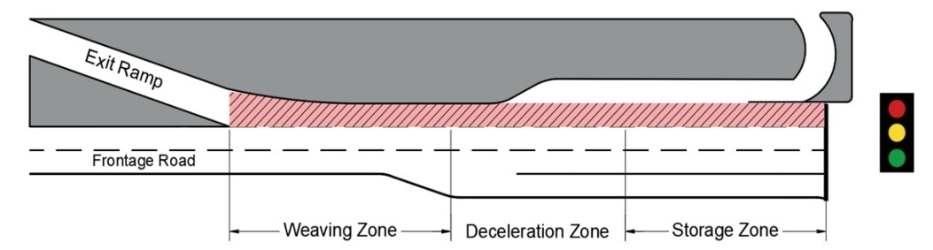
Figure 15-37: Distance from Exit Ramp to Downstream Intersection
15.8.1.4 Left-Turn Deceleration Lane Length
For a left-turn deceleration lane, the total desired length of a frontage road AL (left-turn lane, in this case) includes the sum of the entering taper, the deceleration distance, and the storage length, as shown in
. It also indicates that some deceleration is usually accepted within the through lanes – usually on the order of 10 mph – and that the taper is commonly considered part of the deceleration distance.
Left- and right-turn lanes also consider the taper length to be part of the deceleration length. This guidance provides a sound foundation for frontage road deceleration ALs functioning as intersection left- and right-turn bays as well as right-turn bays servicing driveways and minor side streets.
In rural environments, the 180-foot queue length check value is not long enough to cause blocking of left-turn lanes, since the lanes themselves will exceed this length using the design procedures contained in the RDM. However, for urban design, the left-turn lane length developed using the RDM should be checked against the 700-foot value from research
. If the RDM-based left-turn length is less than 700 feet, the design length should be extended to at least 700 feet to ensure access to the left-turn lane is not blocked by a queue in the adjacent lane.
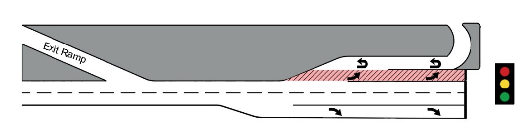
Figure 15-38: Left-Turn Deceleration Lane Length
15.8.1.5 Right-Turn Deceleration Lane Length
The 180-foot queue length check value for rural conditions is not expected to be an issue, since the RDM designed process will always produce a right-turn lane length longer than this value. However, in urban areas the 700-foot long check value should be compared against the RDM-derived right-turn lane length using traditional design procedures. If the urban right-turn lane length is less than 700 feet, extending the lane to at least 700 feet is recommended to lower the chance that access to the right-turn lane will be blocked by a queue in the adjacent lane. See
for a visual of the right-turn deceleration lane length.
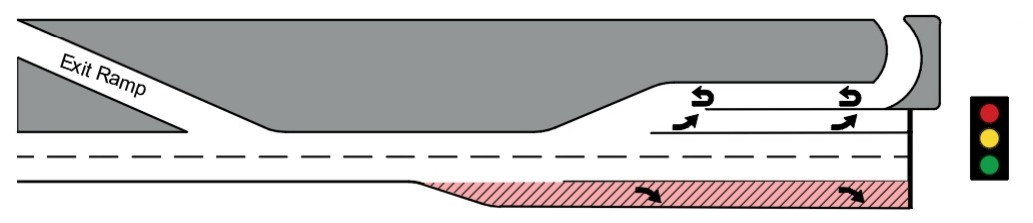
Figure 15-39: Right-Turn Deceleration Lane Length
- Rural Design: 180’ adequate; and
- Urban Design: Recommended minimum 700’ to avoid blocking issues.
15.8.1.6 U-Turn/Turnaround Deceleration Lane
Turnaround lanes are to be provided at all interchanges with major arterials in urban and suburban areas where the freeway lanes are flanked by one-way frontage roads.
Overpasses in these areas should also be arranged to accommodate future turnarounds
. For a typical turnaround design for a diamond interchange, the minimum approach bay length should be 525 feet. However, for interchanges with high ADT (40,000 or greater) or that operate at LOS E or F, storage bay length should be determined through a traffic analysis.When adjacent to left- and right-turn lanes (as shown in
), it is recommended that U-turn lanes in urban areas be at least 700 feet long so that access to left- and right-turn lanes is not blocked by a long queue in the adjacent left turn lane or left turn lane plus through lane at the intersection. Safety analysis of Texas U-turn lane interchanges indicate that longer U-turn lanes were associated with fewer crashes, but this effect is not statistically significant. A minimum length of 525-ft is recommended for U-turn lanes on rural and suburban frontage roads. For high-ADT intersections and/or those with LOS E or F, a traffic analysis should determine if the U-turn lane length is appropriate. The U-turn lane length should be at least 700 feet in length to avoid blocking issues, even if the analysis warrants a shorter length.
For additional information reference
.
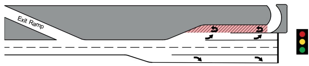
Figure 15-40: U-Turn/Turnaround Deceleration Lane
- Reasonable minimum length (525’) recommended for rural and suburban frontage roads;
- Reasonable RDM recommendation to do a traffic analysis for high ADT intersections and/or those with LOS E or F; and
- : Recommended minimum 700’ to avoid blocking issues.