14.4 Roundabouts
This section discusses the features and design criteria for roundabouts
14.4.1 Overview
A roundabout, in general, is a circular intersection in which traffic travels counterclockwise around a central island and entering traffic yields to circulating traffic. Geometric features slow traffic at the intersection. There are four classifications of roundabouts: mini-roundabouts, compact roundabouts, single-lane roundabouts, and multilane roundabouts (see
). Mini and compact roundabouts are two types of reduced-diameter roundabouts with traversable features. While mini-roundabouts have a fully traversable center island and may have traversable splitter islands, compact roundabouts have a combination of traversable elements but do not provide a fully traversable center island. See
for the varying typical diameters for the four classifications of roundabouts.
Roundabouts have been demonstrated to significantly reduce the number of severe crashes at intersections, improve Level of Service (LOS), and increase capacity. TxDOT has adopted
as the primary source for roundabout design guidelines. The information contained in this section of the RDM is considered a companion guide to
.
Information in Section 14.4 of the RDM takes precedence over NCHRP Report 1043 where a deviation exists within the guidelines.
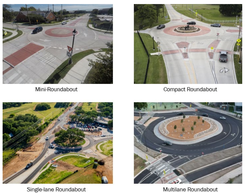
Figure 14-1: Four Classifications of Roundabouts
14.4.2 Goals of a Roundabout Design
Several overarching principles guide the development of all roundabout designs:
- Provide the appropriate number of lanes and lane assignment to achieve adequate capacity, lane volume balance, and lane continuity to ensure that the roundabout operates at an appropriate level of service;
- Design to accommodate the largest anticipated vehicle to enter, circulate and depart efficiently while also providing adequate speed control for passenger vehicles;
- The circulating roadway should be wide enough to accommodate the local jurisdiction largest vehicle (fire truck or city bus), with a truck apron provided around the central island for over-tracking of the rear axles on larger vehicles;
- A central island that is clearly visible from the approach sight distance at the road operating speed in advance of the roundabout. Landscaping or hardscaping within the central island can be effective in restricting sight distance to the minimum requirements while creating a terminal vista on the approach to improve visibility of the central island;
- Drivers must be able to see to the left early enough to safely enter the roundabout. However, excessive intersection sight distance may lead to higher vehicle speeds that reduce the safety of the intersection for all road users (motorists, bicyclists, pedestrians);
- Design such that the driving task is as simple as possible, avoiding the use of spiraled lanes unless warranted by traffic (i.e., dedicated left-turns and other reasons cited in , Section 10.7.7); and
- Site-specific design to meet the needs of pedestrians and cyclists.
14.4.3 Design Process and Design Context
Varying characteristics will determine the selection of a roundabout’s size, lane configuration, and feasibility. Refer to
, Chapter 3, Chapter 8, and Chapter 9 for roundabout performance-based planning and design information and roundabout design principles and objectives.
14.4.3.1 Roundabout Implementation Challenges
It is beneficial to confirm that a roundabout is a feasible solution with respect to site-specific constraints early in the planning process. Advance coordination with adjacent project stakeholders (railroad representatives, neighboring jurisdictions, or local elected officials), review of boundary survey information, and a site visit to observe existing conditions are important steps in validating a potential roundabout installation early in the analysis and design process. Common site-specific constraints consist of:
- Adjacent features that may lead to queue spillback into the roundabout (overcapacity traffic signal, freeway entrance ramp, overcapacity driveway, etc.);
- Unfavorable topography that results in limited visibility, excessive cross slopes in the circulatory roadway, or significantly complicates construction;
- Where the ratio of major roadway traffic to minor roadway traffic exceeds 9:1. Unacceptable delay may result along the minor roadway. Detailed traffic analysis in this situation is recommended. Refer to Chapter 12 of the for additional guidance;
- Significant pedestrian and bicycle movements at a near- or over-capacity roundabout;
- Within a coordinated traffic signal network. A roundabout may disrupt progression and have a negative impact on the efficiency of a signalized corridor. If possible, converting a corridor to all roundabouts may provide operational efficiencies. Refer to Chapter 9 the for more information regarding segment analysis;
- Roadways with reversible lanes for alternating peak period traffic flows;
- At or adjacent to an at-grade railroad crossing; and
- Environmental factors. Proximity of historical sites, ROW constraints, or other environmental constraints adjacent to an intersection.
A performance-based mindset affords the creation of functional designs with the most flexibility. Due consideration of the intersection--specific physical and traffic conditions throughout the life cycle of a subject intersection will be one of the key contributors to the success of a roundabout installation. TxDOT has several tools and resources available for the collection and analysis of traffic data to prepare an operations analysis, including the data sources outlined in the
, Chapters 10, 11 and 12.
14.4.3.2 Identify Design Considerations
Within the planning and conceptual process of a proposed roundabout, a documentation of roundabout parameters is encouraged so the engineer-of-record and corresponding reviewing agencies can agree to the parameters selected for a roundabout’s design. Determination of the following parameters after an operational analysis and prior to the concept roundabout sketch can reduce re-sketching and future requests for changes to a roundabout design:
- Inscribed circle diameter (ICD);
- The proposed surface pavement section (concrete or asphalt);
- Mountable/non-mountable curb types;
- Gutter pan dimensions and slopes, if applicable;
- Minimum and maximum performance check values;
- Truck traffic accommodation (straddled lane design vs non-straddled), formerly known as Case 1, Case 2, and Case 3 (refer to , Section 9.7.1);
- Traditional lane geometries, spiraled lanes, buffered lanes, or turbo roundabout design;
- Pedestrian and bicycle facilities, including buffer width between the back of curb;
- The inclusion of bike ramps;
- Proper illumination on the perimeter roadway and within the center landscaped island;
- Maximum cross slopes in the circulatory;
- Adjacent driveway accessibility; and
- If multilane, the use of a traffic control signal with a pedestrian signal head, a pedestrian hybrid beacon (PHB), a pedestrian actuated rectangular rapid flashing beacon (RRFB), or a raised crossing as a crosswalk treatment.
The performance-based geometric design of a roundabout is an iterative process, as outlined in
, Exhibit 9.1. It may take multiple revisions to the size of the ICD and the location of the ICD before an optimized solution is arrived at for the subject intersection.
Considerations to the ICD size and placement of a roundabout consist of:
- Traffic patterns and volumes;
- Existing and/or proposed ROW boundaries;
- Connecting roadway alignments and centerlines;
- The footprint of the existing intersection;
- Circular versus elliptical design;
- The effect the diameter has on geometric speed control and resulting circulating speeds;
- If intersecting roadway legs are skewed, or normal to the intersection;
- The design vehicle and check vehicle(s) – see for a list of typical design and check vehicles and for an explanation of design and check vehicles;
- Oversize or overweight vehicles (OSOW);
- Environmental considerations; and
- Grade considerations.
Table 14-1: Common ICD Ranges
Source: Adapted from NCHRP Report 1043
Roundabout Configuration | Typical AASHTO Design Vehicle 1 | Typical AASHTO Check Vehicle | Common ICD Ranges |
Mini-roundabout | Local jurisdiction largest apparatus (fire truck or city bus) 2 | WB-62TX | 70-ft to 90-ft |
Compact Roundabout (non-traversable central island) | Local jurisdiction largest apparatus (fire truck or city bus) 2 | WB-62TX | 90-ft to 110-ft |
Single-lane roundabout (non-traversable central island) | Local jurisdiction largest apparatus (fire truck or city bus) 2 | WB-62TX, WB-67 or OSOW | 110-ft to 150-ft |
Multilane roundabout (2 lanes circulating) 3 | Local jurisdiction largest apparatus (fire truck or city bus) 2 | WB-62TX, WB-67 or OSOW | 140-ft to 200-ft |
Multilane roundabout (3 lanes circulating) 3 | Local jurisdiction largest apparatus (fire truck or city bus) 2 | WB-62TX, WB-67 or OSOW | 180-ft to 220-ft |
Notes: | |||
| |||
Mini-roundabouts are not common on State routes, due to the higher speed context and presence of added large trucks. Locating mini-roundabouts in suburban areas with moderate speed context is feasible with added approach treatment of reverse curves and longer splitter islands.
Compact and single-lane roundabout design is commonly influenced by design vehicle swept path requirements. Rural design requires provision of a visibility package of approach geometry (frequently using reverse curves), signs, illumination, and markings.
14.4.4 Design Parameters
The following design parameters and their associated values shall be documented and agreed upon by all relevant parties prior to a conceptual or schematic roundabout design. Advance determination of these parameters and values is beneficial to reduce the potential for future re-work of the roundabout design.
- Inscribed Circle Diameter, face of curb to face of curb (FOC-FOC);
- Circular ROW Footprint (ICD plus sidewalk and buffer strip, ft.);
- Design and Check Vehicle(s), per movement (i.e. If a larger vehicle is known to only make a right-turn at a given intersection, the remaining turning movements may be assigned a separate check vehicle) (see );
- Fastest Path Geometric Entry Speed, R1 (method: , Section 9.4);
- Fastest Path Entry/Circulating Speed Differential (V1 to V2) (see );
- Minimum Circulatory Cross Slope (%);
- Maximum Longitudinal Grade (% approach or circulating);
- Maximum Cross Slope (low side if circulatory roadway is tipped [i.e. tilted plane design]);
- Volume Range (sum of entering and conflicting volumes);
- Splitter Island Length (length will vary depending on if posted regulatory speed is less than or equal to 35 mph, or greater than 35 mph);
- Entry Curb Radius (near the yield line, ft.);
- Exit Curb Radius (ft.);
- View Angle (angle in degrees from a straight-ahead driver’s view) (see );
- Entry Width (see );
- Exit Width (see );
- Circulatory Roadway Width, FOC-FOC (ft.);
- Inner Circulatory Lane Width (ft.);
- Outer Circulatory Lane Width (ft.);
- Truck Apron Width (ft.) (see );
- Exit tangency (for path overlap check). Refer to , Exhibit A.18, and see RDM Section 14.4.5.6;
- Curb Offsets (ft.);
- Buffer Width (FOC to Sidewalk, ft.);
- Crosswalk Pedestrian Refuge Width (ft.);
- Crossing Accommodation (Traffic Control Devices and/or the use of raised crosswalks); and
- Maintenance of Traffic during construction (highway and/or lane closures).
, Section 10.7 provides justification for added emphasis of the following in multilane roundabout design:
- Geometric speed control;
- Avoidance of complicated lane configurations and use of single-lane entries and exits where the capacity trade-off is negligible;
- Development of natural parallel entry and exit paths;
- Provision of optimal approach lane markings; and
- Overhead signs for lane designation.
to
highlight ranges of common design considerations for various geometric parameters of roundabouts for the four different classifications.
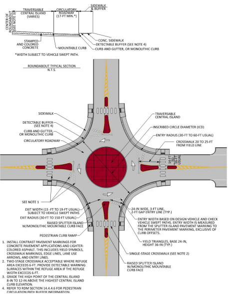
Figure 14-2: Mini-Roundabout Design Parameters
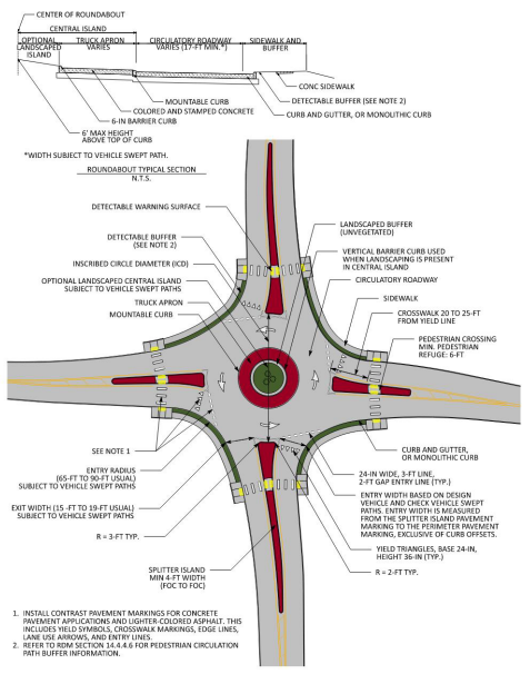
Figure 14-3: Compact Roundabout Design Parameters
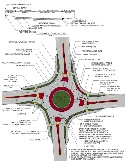
Figure 14-4: Single-Lane Roundabout Design Parameters
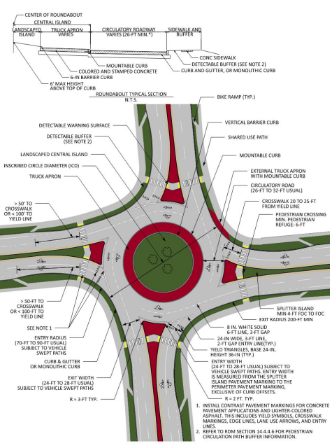
Figure 14-5: Multilane Roundabout Design Parameters
14.4.4.1 Entry and Exit Geometry
, Section 10.6.4 and Section 10.6.5 detail entry and exit design for roundabouts.
The entry width is measured from the center of the pavement marking that is adjacent to the splitter island to the center of the pavement marking adjacent to the exterior curb, or if a gutter section is present, the width is measured to the edge of the traveled way.
The design vehicle and check vehicle must be able to navigate the entry of a single-lane roundabout with a one-foot shy distance from the wheel path to the face of curb or edge of traveled way. When a WB-62TX is to be accommodated at a single-lane roundabout as the check vehicle, a wider entry width may be required due to the swept path of the rear tandem axle tires relative to the cab’s front tires.
At multilane roundabouts the entry width will depend on the design case. If stay-in-lane design is employed, then the resulting entry width will be greater than the typical straddle lane design entry width to accommodate the check vehicle in-lane while providing the necessary gore width between adjacent entry lanes. Individual lane widths for two-lane entries should remain in the 12-ft to 13-ft range. Maintaining trucks in-lane has safety consequences for other users including longer pedestrian crossings and higher in-lane speeds. Generally, promoting in-lane design for the design vehicle should be restricted to interchanges.
Exit design will rely heavily on single-lane or multilane designation, subsequent performance checks (fastest path and check vehicle), and the exit alignment that connects the roundabout to the adjacent roadway. Straighter exit paths provide ideal sight of the exit crosswalks, but exit speeds can increase, which places a greater emphasis on controlling entry speed.
14.4.4.2 Circulatory Roadway
For single-lane roundabouts, an 18-ft to 20-ft (face of curb to face of curb) circulatory roadway width is typical. For two-lane straddle-lane roundabouts, circulatory width is commonly in the range of 26-ft to 32-ft. For two-lane stay-in-lane design for trucks (“buffered lane design”), the circulatory width may be wider to accommodate the check vehicle being analyzed for both lanes in combination with the gore area separating the two circulatory lanes. Circulating lane widths should split the remaining circulatory roadway evenly.
14.4.4.3 Splitter Islands
, Section 10.6.1 and 10.14.2 discusses splitter island types and lengths. Splitter island design discussion can be found throughout
due to a splitter island’s influence on pedestrian and bicycle accommodation, speed control, deterring wrong-way driving, and space allocation for traffic control devices. Splitter islands may be bounded by full-height barrier curb, mountable curb, or a flush fully traversable painted area. The context of the intersection should dictate the elements chosen for the splitter island. The minimum length of a splitter island for low-speed urban design is 50-ft. See
for additional guidance for splitter islands at highspeed context roundabouts.
14.4.4.4 Truck Apron
, Section 10.5.2 discusses truck aprons. Guidance for truck apron sizing, materials, and even the relationship that truck aprons provide to maintenance can be found within
. It is important for the truck apron to have contrasting color and texture from the circulating pavement within the roundabout. This contrast allows drivers, especially during nighttime conditions, an increased ability to identify the limits of the circulatory roadway.
Consider the installation of yellow raised pavement markers spaced at 4-ft to 6-ft along the perimeter of the truck apron curb for mini-roundabouts to enhance nighttime visibility of the central island.
14.4.4.5 External Truck Apron
When performing the check vehicle performance checks, the usage of an external truck apron (a.k.a. “perimeter truck apron”) may be required to accommodate the wheel path of the check vehicle. The horizontal geometry of external truck aprons relies on the designer’s understanding of how to navigate the check vehicle through the respective movement (typically the right-turn but may also be required for through movements).
, Section 11.6 discusses the use of external truck aprons. The use of external truck aprons should be avoided, if possible, by incremental modifications to the approach and entry geometry, entry radius, exit geometry, and exit radius, such that the modifications still result in a design that is validated by the standard performance checks.
14.4.4.6 Pedestrian and Shared-Use Crossings
, Section 10.4.7 highlights the three basic types of pedestrian and bicycle crossings at roundabouts, angled, straight, and z-crossing. A best practice at roundabouts, especially where bike ramps are implemented, is the use of tactical directional indicators (TDIs). Refer to
, Section 10.4.3 for information regarding TDIs. Key considerations for pedestrian and bicycle crossing design at roundabouts consist of:
- Adequate space for pedestrian and bicycle refuge within the splitter islands;
- Bicycles that haul child trailers or cargo trailers may require additional width beyond the minimum prescribed six feet from face-of-curb to face-of-curb;
- Single-stage crossings where the refuge width in the splitter island is less than 6- ft and detectable warning surfaces (DWS) are omitted, versus a typical two-stage crossing where pedestrian refuge is accounted for between opposing directions of travel within the splitter island;
- Positioning and alignment of TDIs, when applicable; and
- 20-ft to 25-ft distance from the entry line adjacent to the nearest point of the designated crossing. Refer to .
Pedestrian circulation paths at roundabouts between crosswalks shall be separated from the curb with landscaping or other nonprepared detectable surface with a minimum width of 24 inches. Exception: If a curb-attached pedestrian circulation path is provided, it shall have a continuous and detectable vertical edge treatment along the street side of the path, from crosswalk to crosswalk. The bottom edge of the vertical edge treatment shall be 15 inches maximum above the pedestrian circulation path. Refer to Section R306.4.1.1. and R306.4.1.2. of the
, or latest version.
14.4.5 Performance Checks
The validation of a roundabout’s horizontal geometry is one of the most important steps in the design process. Roundabout performance checks should be completed prior to any vertical design or supplemental detailing of a roundabout.
, Chapter 9 highlights the various current industry standard performance checks associated with fastest path speeds, sight distance, view angles, vehicle path alignments, design and check vehicles, and bicycle and pedestrian wayfinding and crossing assessment. Appendix A of
outlines performance check techniques. Performance checks completed in CAD software are required to remain a part of the project’s design files throughout the project life cycle, including postconstruction, in case an audit of the roundabout occurs after the roundabout is constructed.
14.4.5.1 Documentation Requirements
A roundabout design performance checks package is required. The documentation should be compiled in a series of design check diagrams as follows:
Series 1 –
Overview and Horizontal Design - A dimensioned general layout drawing showing:- Inscribed circle diameter, circulatory roadway width, entry and exit widths, splitter island lengths, and truck apron widths;
- Pedestrian crossing locations/width, composition, raised/flush, markings, when applicable;
- Bicycle lane/approach & termination point, when applicable;
- A typical cross-section of the roundabout’s central island (mounded), roadway and truck apron compositions and integration, widths, slopes, and curb standards;
- Location of nearest entrances from the inscribed circle diameter and the nature of the land use; and
- Proximity of roundabout to traffic signal or other intersections.
Series 2 -
Geometric design speed (‘fast path’) diagrams for each approach, entry, circulating, and exit are required. Roundabouts must be designed to promote geometric speed control per theoretical fastest path speeds in accordance with
, Section 9.4 and
. Left offset of the approach alignment increases the space for the approach curve to be well-developed for entry speed reduction. Geometric entry speeds, measured according to
, must be less than 25 mph along the fastest through movement path for single-lane roundabouts and less than 28 mph for the fastest through path for multilane roundabout entries. Approach roadway design speeds and fastest theoretical paths are to be shown. Fast path radii and the range of corresponding speeds based on a (+)2.0% cross slope and (- )2.0% cross slope are to be annotated on the design checks submittal Series 2 diagrams.Series 3 -
Truck swept-path diagrams are to be developed using AutoTURN®, Vehicle Tracking, or similar software, with depiction of the design and check vehicle(s) for all of the anticipated turning movements. Design and check vehicles will validate the width of lanes and the circulatory roadway, e.g., S-BUS-40 or CITYBUS. The check vehicle shall validate the width of the central island truck apron and entry and exit widths using a 1-ft shy distance from face of curb (FOC) to the vehicle wheels. The truck cab of a design and check vehicle will typically stay on the circulatory roadway when running swept-path analysis with all tires remaining at least 1-ft from the face of curb.Series 4 –
Stopping sight, intersection sight and view angle diagrams accounting for both vertical approach grades and horizontal alignments. Sight distances must account for driver eye height and height of objects. This is for the purpose of user safety and to establish limits to planting scheme/landscaping for the mounded central island and splitter islands. Refer to
, Section 9.5.Series 5 –
Ancillary elements diagrams include light pole locations and traffic control devices such as signing and pavement markings (refer to the
). These elements are generally developed after schematic design; however, with multilane roundabouts, it is necessary to design markings at the concept or schematic stage to validate the use of exclusive lanes and spiraled geometry.14.4.5.2 Geometric Speed Control (Fastest Path Speed Measurement)
, Section 9.4.1 and Appendix A.1 covers the assessment of speed control for a roundabout’s horizontal geometry. Section 9.4.2 of
outlines the process for developing fastest path alignments using the spline technique. Key considerations for fastest path speed assessment for roundabouts consist of:
- Correct placement of node points to develop the associated spline;
- Using Control Points (MicroStation) as a method for creating the spline within CAD software;
- Using the correct offset dimension for the center of vehicle location relative to curbs or pavement markings;
- Producing a spline that is located within 5.0-ft to 5.1-ft of the controlling offset feature (face of curb or pavement marking), or 3.0-ft to 3.1-ft where opposing traffic adjacent to the roadway centerline is separated by 5-ft or greater;
- Avoiding the addition of node points beyond the typical nine nodes for a through movement, seven nodes for a right-turn movement, and nine nodes for a left-turn movement;
- Adjusting node points along the 165-ft, 215-ft, or 265-ft offset arcs from the ICD when creating a spline that does not cross the minimum 5.0-ft offset along the approach or exit geometry of the roundabout;
- Maintaining less than a maximum differential between V1 to V2 and V1 to V4 of 10 mph;
- Use of a maximum allowable fastest path entry speed, V1, to a value of 28 mph for a multilane entry design;
- Use a consistent 70-ft arc length along the spline when calculating the corresponding R-value; and
- Comparing R2 values on opposite sides of the central island. Unbalanced R2 values can be an indicator that the ICD chosen for the roundabout design may not be optimized and should be shifted in the direction of the higher R2 value to provide enhanced and balanced speed control.
provides a graphical representation of the corresponding theoretical maximum fastest path speed alignments for a left-turn (R4/V4), through movement (R1/V1, R2/V2, R3/V3), and a right-turn (R5/V5).
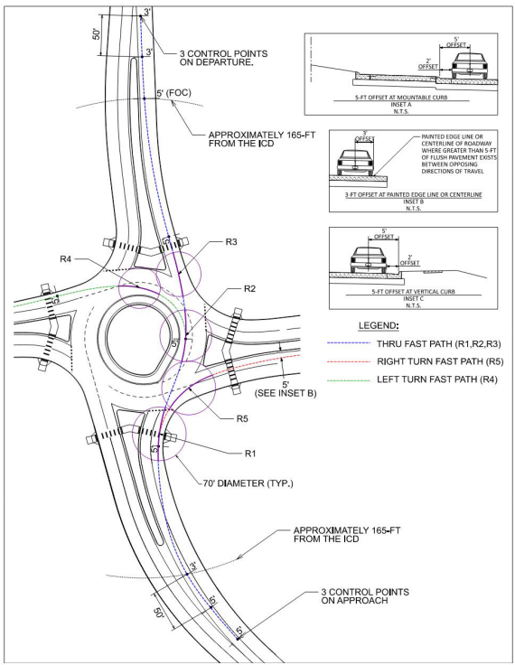
Figure 14-6: Geometric Speed Control Fastest Path Performance Design Checks
14.4.5.3 Path Overlap
Path overlap is a detrimental condition that can arise from inadequate horizontal geometry of multilane roundabout entries and exits, as discussed in
, Section 9.6. Providing tangency to adjacent entry and exit lanes has emerged as an important feature of multilane design to discourage vehicle lane changing within the circulating/conflicting conflict zone areas of a roundabout.
visualizes the method for checking path overlap. The amount of tangent to avoid entry path overlap and exit path overlap between point A to point B and point B to point C, respectively, is 30-ft to 50-ft and 40-ft to 60- ft. One check of adequate entry geometry is for the tangent point at point A to be located within 5-ft of the entry yield line. Additional tangency beyond 5-ft prior to the entry line should be avoided so the speed-controlling entry radius is not shifted too far in advance of the typical crosswalk location.
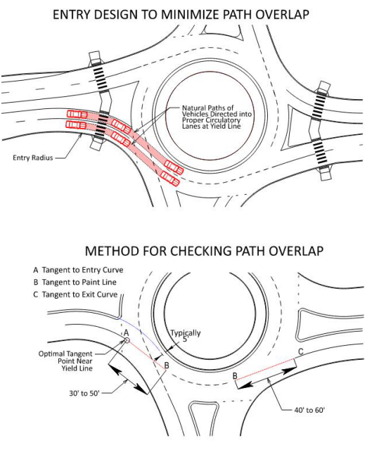
Figure 14-7: Natural Path Performance Design Checks
14.4.5.4 Design and Check Vehicles
, Section 9.7 covers the topic of design vehicles. The largest anticipated non-articulated vehicle that is needed to be fully accommodated in the circulating roadway within the roundabout (the “design vehicle”), and the largest anticipated articulated vehicle subject to use a given roundabout (the “check vehicle”) are key roundabout design parameters. Typical design vehicles are the largest local jurisdiction fire department apparatus or a city bus. An additional check vehicle that includes articulation, such as a WB-40, WB-62TX, or WB-67, should be analyzed in properly sizing entry widths, circulatory roadway widths, truck apron widths, exit widths, and determining the final location of proposed curbing within and adjacent to a given roundabout.
The selection of the design vehicle and the check vehicle to navigate the intersection throughout the life cycle of the intersection is necessary prior to preliminary design. Consideration should be given for individual movements at an intersection. The design vehicle and check vehicle may only need to make thru movements and may not need to make left or right-turn movements on or off the major roadway. Adjacent land use, trip generators, and local and regional routing may factor into the verification of movements of the check vehicle on a case-by-case basis. The selection of the appropriate vehicles should be vetted with TxDOT staff, and possibly with local agency staff, local stakeholders, and potential permitted load routing.
, Chapter 9 and Appendix A.4 outlines vehicle performance checks for design vehicles and check vehicles.
Key considerations for design vehicles and check vehicles at roundabouts consist of:
- The appropriate design case- straddle lanes or stay-in-lane (refer to , Section 9.7.1 for more information);
- The width of outer lane or inner lane curb offsets;
- If curb and gutter is proposed, the dimensions of curb and gutter are important in keeping design and check vehicle wheel paths off the gutter pan;
- Allowance of a shy distance between the vehicle’s outer wheel path and face of curb (or edge of traveled way);
- Analyzing left-turning articulated vehicles within the inner lane of a multilane circulatory to determine the appropriate truck apron width;
- Selection of the largest anticipated vehicle (i.e., the check vehicle) that may need to navigate the roundabout. OSOWs would be classified as a check vehicle if determined to be needed along the route where a proposed roundabout is being considered. For the check vehicle, external truck aprons may be used to facilitate the proper accommodation of an OSOW to avoid widening travel lanes adjacent to and within the roundabout; and
- The use of a WB-62TX check vehicle in lieu of a WB-67 or WB-62 check vehicle. WB-62TX represents a WB-62 with a 53- ft trailer instead of the WB-62’s 48-ft trailer. Given that most tractor-trailer combinations will haul 53 ft trailers with their rear tandems moved, it is appropriate to use the WB-62TX at locations other than interstate ramp terminals or near truck terminal locations.
shows common design and check vehicle specifications based on
for a CITY-BUS and a WB-67. The WB-62TX designation, although not an official designation by AASHTO, is a common tractor-trailer configuration in Texas and is recommended to be used as a check vehicle where a WB-67 configuration is not anticipated.
of this manual has additional information on Design and Control Vehicles.
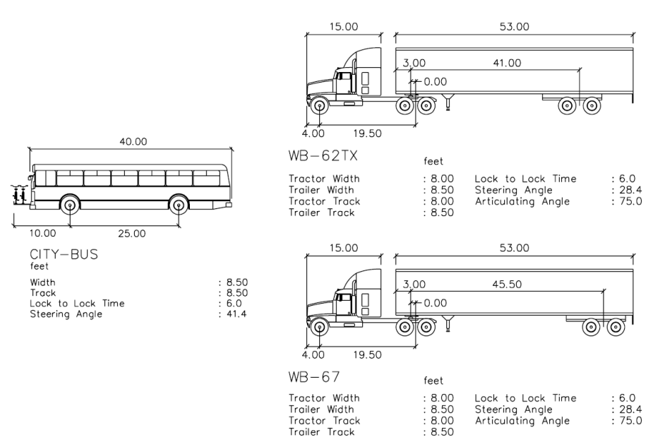
Figure 14-8: Design Vehicle and Check Vehicle Templates
14.4.5.5 Truck Accommodation at Multilane Roundabouts
Straddle lane design is presumed unless it can be shown that a given intersection is anticipated to accommodate a significant amount of daily or peak period truck traffic. If an intersection is anticipated to have 120 trucks per hour, or more, (one truck every 30 seconds) on a given approach, stay-in-lane design is recommended to be implemented. Contexts for stay-in-lane design will be roundabouts proposed at interchanges, near common OSOW facilities and freight trip generators.
The need for stay-in-lane design increases at roundabouts that are anticipated to experience near- or at-capacity conditions in the peak periods. This is due to the additional time gap needed for large trucks to be able to enter safely into the circulatory while yielding to circulating/conflicting vehicles. A stay-in-lane design in this situation allows passenger vehicles to accept smaller gaps in traffic and proceed through the roundabout while the large truck waits for an extended gap in traffic.
14.4.5.6 View Angle
View angle is the angle created by a driver yielding at the entry line while looking to their left to identify oncoming vehicles that will conflict with their entry path. As the angle that a driver is required to turn their head to identify oncoming traffic increases, vision and detection of potential conflicts becomes increasingly difficult. This may especially be the case with drivers with chronic neck pain, injuries, or elderly drivers. View angle is also a factor with large trucks, whereby the side window placement is commonly a constraint for sight to the left at acute angles.
, Exhibit A.16 and
depict the arrangement of vehicles for angle of visibility checks. If an oncoming vehicle’s location crosses out of the 105- degree cone of vision for this visibility-to-the-left performance check, drivers will not be able to move close to the yield line for normal sight of oncoming traffic to the left. In such cases, the approach and entry geometry must be modified to improve the view angle. Skewed intersections and right-turn yielding bypass lanes are typical examples where view angle performance checks are vital to providing visibility-to-the-left.
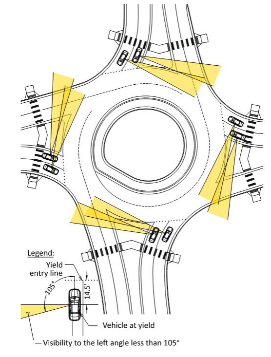
Figure 14-9: View Angle Example
14.4.5.7 Sight Distance and Visibility
, Section 9.5 documents the relevant sight distance checks for roundabouts. Stopping sight distance, intersection sight distance, and decision sight distance are all relevant to roundabout geometric design. Key considerations for adequate sight distance at roundabouts consist of:
- Proper grading and clear zones within the central landscaped island of the roundabout to accommodate the circulatory roadway’s stopping sight distance requirement (refer to , Exhibit 14.9);
- Avoidance of perimeter landscaping, signage, street furniture, franchise utility equipment, and other appurtenances that may restrict sight distance;
- Avoidance of splitter island treatments that may restrict stopping sight distance, especially for approach geometries of skewed intersections and offset left designs. Trees, vertical walls, and franchise utility equipment are a few common obstructions that should be avoided in a splitter island within 50- ft of a roundabout’s ICD; and
- Avoidance of an abundance of sight distance. When the central landscaped island of a roundabout is graded flat or lacking berm height, it allows approaching motorists to see through a roundabout. Similarly, if the approaching splitter island and perimeter quadrant to the left of an approaching driver is vacant, it can allow for an approaching motorist to identify the absence of potential circulating/conflicting traffic upon their arrival at the entry of the roundabout. This abundance of sight distance can result in drivers maintaining faster speeds as they recognize no conflicts will be present upon their arrival at a roundabout. Providing restrictive sight elements outside of sight distance envelopes can reinforce speed reduction for approach drivers resulting in safer driving conditions at the crosswalk and entry of a roundabout.
14.4.6 Special Considerations
To supplement
, the following roundabout design considerations are presented to increase design flexibility for complicated design context of roundabouts in Texas.
14.4.6.1 Oversized and Overweight Vehicles
Oversized and overweight vehicles are common on Texas roads. Due to the presence of wind turbine tower trailers, heavy construction equipment trailers, and other large transport trucks, it can become necessary to specifically modify a roundabout design to accommodate an OSOW. Coordination should take place between the intersection location’s TxDOT Area Office and the engineer-of-record to determine if permitted loads are present at the subject intersection, and if so, the specifications of the largest anticipated vehicle.
, Section 10.5.4 discusses the design of roundabouts for OSOWs.
14.4.6.2 High-speed or Intermediate Speed Approach Design
Note for the general purposes of superelevation methodologies, intermediate speeds are classified as between 50-60 mph (see
). Roundabouts installed in these contexts require recognition of the human factors needs of the driver to detect, recognize, and react to the presence of a roundabout while approaching the intersection at a higher rate of speed.
The primary safety concern in intermediate/high-speed context is clarity of the driving situation, that is, to make drivers aware of the roundabout with ample distance to comfortably decelerate to the appropriate speed. Therefore, designs should abide by these principles:
- Provide the desirable forward stopping sight distance of the entry point based on approach operating speed;
- Align approach roadways and set vertical profiles to make the central island conspicuous and mound the central island 3.5-ft. to 6-ft;
- Splitter islands should extend upstream of the yield line to the point at which entering drivers are expected to begin decelerating. A minimum length of 200- ft is recommended for high-speed approaches;
- It is typical for the approach treatment to extend the project limits to greater than 500-ft from the center of the roundabout. Approach curves should be gentle, become successively smaller and should be sized based on the design speed and expected speed change of 15 to 20 mph per successive horizontal curve; and
- The use of a tangent between horizontal curves is recommended unless the curves have large radii and there is no required superelevation of either curve. A common tangent length is 100ft. The use of a tangent has been shown to eliminate truck rollovers where curve radius and curve length are relatively small in a high-speed context. Refer to the on TxDOT.gov for additional information.
For approaches to roundabouts see
for appropriate superelevation methods.
Guidance provided in
, Section 10.14 combined with
aids in designing splitter island length, horizontal curves, and superelevation to treat roundabouts in an intermediate/high-speed context.
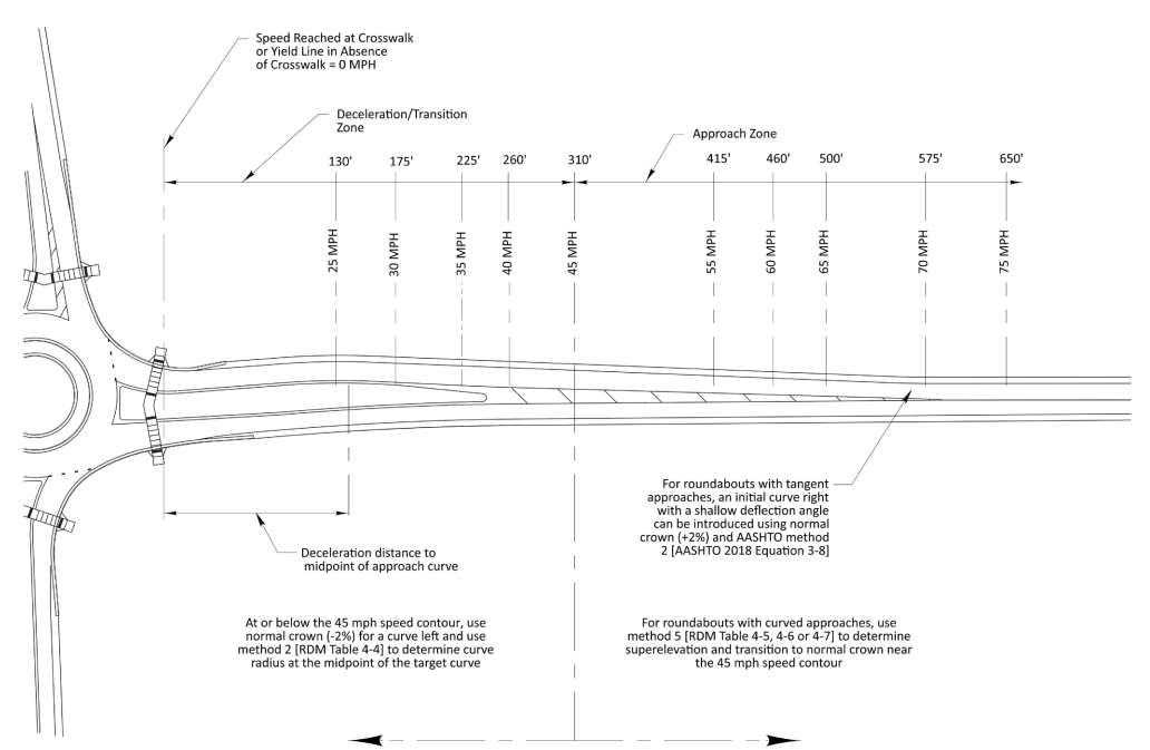
Figure 14-10: High-Speed Approach Design Approach and Deceleration Zones
14.4.6.3 Spiral Design
Spiral circulatory geometry is commonly used when a dedicated left-turn lane is implemented at a multilane roundabout.
shows an example of a spiraled movement. Spirals can also be applied for any 2x1 lane configuration roundabout where the single circulating lane spirals to the portion of the roundabout where a resulting two lanes are located within the circulatory. Benefits of using spirals in roundabouts consist of:
- Guiding the circulating vehicle to the outer lane of the two-lane circulatory;
- Where adjacent driveways are located close to the roundabout, or a heavy right-turn movement is common at the adjacent downstream intersection;
- Reduces the size of the conflict zone, the area where entering vehicles interact with circulating/conflicting vehicles; and
- Reinforce yield behavior for the outer lane entering driver that is yielding at the two-lane entry because the spiral makes it more apparent that the circulating vehicle will cross the entry path of this entering lane.
Figure 14-11: Spiral Design Example
Source: Kyle Kruppa
14.4.6.4 Buffered Lane Design
The concept of buffered lane design has emerged from discussions in the U.S. of how to adapt turbo roundabout design to conventional U.S. multilane roundabout design. Buffered lane design is also emerging as a retrofit solution where constructed roundabouts may have excessive ICDs and/or circulatory widths.
The benefits of buffered lane roundabouts are evident with improved lane discipline for passenger vehicles, reduced vehicle speeds and failure-to-yield conflicts, while also providing lane discipline for articulated trucks. Where existing multilane roundabouts have been built with a surplus of circulatory width, buffered lane design represents a low-cost solution to narrow circulating lanes which in turn enhances speed reduction and lane discipline without having to consider full-depth reconstruction as part of a safety improvement.
Applying buffered lane design to initial installation is done more deliberately while upholding the basic principles of ICD size, geometric speed control, and approach alignment.
shows an example of a buffered lane design roundabout.
Figure 14-12: Buffered Lane Example (applied as a retrofit without moving curbs)
14.4.6.5 Turbo Roundabouts
By definition, a turbo roundabout includes a radial entry and exit design, employs orbiting geometry within the circulatory to facilitate the origin-destination path through the roundabout, and makes use of raised dividers to channelize vehicles to enforce in-lane driving. Implementation of turbo roundabouts is in its infancy stage in the U.S. since only a handful of turbo roundabouts have been built in the U.S. Designers must exercise caution when selecting this type of roundabout. Refer to Section 10.7.8 in
for additional information regarding turbo roundabouts. An example of a constructed turbo roundabout in the U.S. is shown in
.
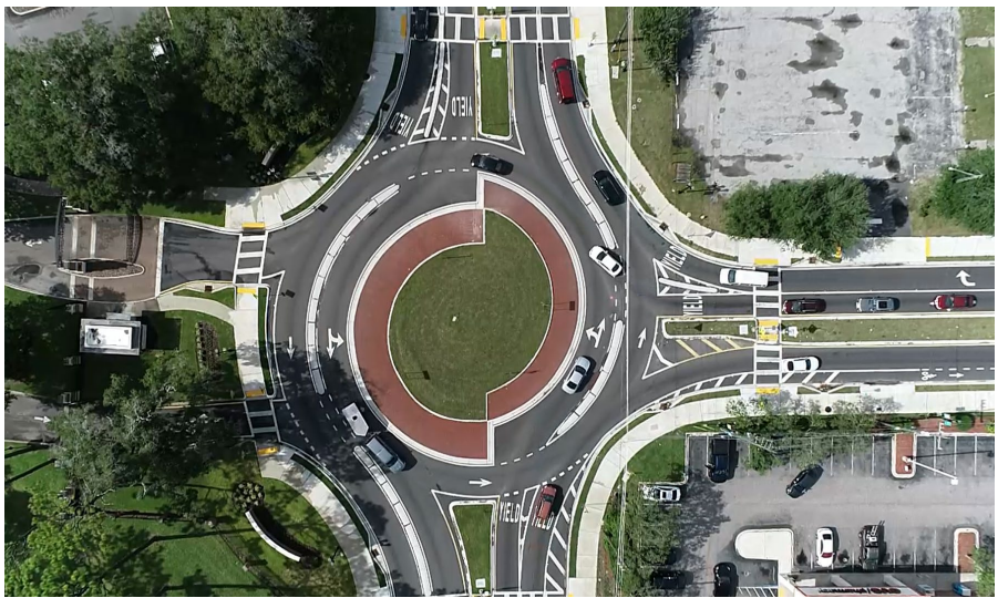
Figure 14-13: Example Turbo Roundabout (Jacksonville, FL)
14.4.6.6 Expandable Design
Interim and ultimate lane configuration roundabout analysis may result in a preferred method of using future expandable design. If within the operational analysis a roundabout is shown to benefit from a reduced lane configuration on opening day for the first 10 to 15 years of its existence, then expandable design should be considered. Reducing the number of entry lanes on a given approach will result in less conflict points, shorter crossing distances for pedestrians and bicyclists, and provide for safer operations.
, Section 10.8 discusses the use of expandable design, including commentary on the advantages and disadvantages of expanding outward versus expanding inward.
14.4.6.7 Railroads and Preemption
, Section 12.7 provides guidance on roundabouts near rail crossings. Roundabouts with at-grade rail crossings nearby or within the roundabout have been constructed at many locations in the U.S., including downtown Daingerfield, TX. The decision of whether to install crossing gates at a roundabout may be considered early in the planning or design process. Early and up-front coordination is highly recommended with the governing railroad agency if a roundabout is proposed near an at-grade rail crossing. Risk analysis, traffic queue calculations, train crossing frequency and duration, and proximity of the roundabout to the rail crossing are important factors when considering a potential roundabout installation in this type of context.
14.4.6.8 Median and Access Management Benefits and Considerations
Various topics arise when considering the effect of roundabouts and access management. Roundabout corridors can replace median-opening cross-access along an undivided or divided roadway. Motorists can make use of U-turn movements at a roundabout to facilitate what would previously be a left-turn movement to access a property on the opposite side of the street.
A corridor of roundabouts combined with continuous raised medians provides amplified safety benefits by eliminating high severity crash types such as head-on and right-angle or side-impact collisions. Roundabouts provide U-turns for all vehicle types at low speeds, eliminating the risks of mid-block left-turns and U-turns across opposing high-speed traffic. Median width can thereby often be reduced since mid-block turning movements are prohibited. This strategy is called “wide nodes and narrow roads”. Severe crash risks are reduced within the narrowed mid-block roadway section and at the intersections. Roundabout spacing in this type of corridor is important to consider to limit the distance required for a vehicle to make a U-turn to access adjacent property.
Driveway locations relative to a roundabout can typically be moved closer to the intersection with a roundabout, as compared to a conventional traffic signal installation, due to shorter queue lengths. Other factors influencing the location of a driveway relative to a roundabout consist of:
- The location of a bike ramp or crosswalk that may conflict with the driveway;
- A queue spillback analysis at the entry of a roundabout;
- The frequency of left-turns wanting access to the driveway; and
- The resulting storage length for a yielding right-turn bypass lane.
14.4.7 Preliminary and Final Design
14.4.7.1 Pavement Design
Determination of a concrete or asphalt pavement section is important to the schematic and preliminary design of a roundabout due to the subsequent performance checks for fastest path and design vehicles. Determining whether the roadway will have a monolithic curb, or a separate curb and gutter section may have a direct impact on the curb offset location and the subsequent performance checks performed for a roundabout.
14.4.7.2 Vertical and Grading Design Best Practices
For constructability and grade control, setting up additional alignments and profiles of the edge of pavement produces optimal grade control for retrofit designs. Developing a grading surface that closely follows existing topography or the natural grade of the intersection often results in a tilted plane, also known as “tipping the circle”. Tipping the circle requires gradual transition from sloping in on the high side to sloping out on the low side. The preferred maximum cross-slope of the low side should be 2-percent to prevent truck roll-overs.
Additional considerations for the proper accommodation of OSOWs may be needed for vertical clearance checks of lowboys and other vehicles that have a reduced vertical envelope. In rare cases, the height of the center island truck apron and the circulatory grade may need to factor into the check vehicle vertical clearance.
For additional guidance, refer to
, Chapter 11.
14.4.7.3 Drainage
Ideally, drainage structures will be installed outside of the limits of the ICD of a roundabout. Inlets upstream of crosswalks in advance of a roundabout and downstream of the ICD typically provide enough capture from runoff within the footprint of a roundabout. Minimum and maximum slopes should be analyzed, including a typical cross slope within the circulatory roadway of 1.5 percent to 3.0 percent. Chapter 10 of
provides guidance on drainage best practices and examples.
14.4.7.4 Pavement Markings
Pavement marking plans should be separated from signing plans for clarity. Legends are encouraged on pavement marking sheets to convey the TxDOT bid item numbers and an accurate description of the bid item, including color, width, length, and gap length of the pavement marking.
to
represent TxDOT’s preferred pavement markings for roundabouts.
, Chapter 12 contains supplemental information regarding pavement markings at roundabouts. The
also serves as a resource in preparing pavement marking designs. Key considerations for pavement markings at roundabouts consist of:
- The use of standard arrows in lieu of fish-hook arrows ( , Exhibit 12.6). TxDOT’s preference is to use traditional arrows for all approach and circulating area lane use arrows;
- Worded or route destination shield symbols used at interchanges or other designated facilities;
- The selection of circulating lane separation line types for multilane roundabouts. Several different methods of marking the circulatory roadway have emerged in roundabout guidelines and in practice, including a solid-dotted combination ( , Exhibit 12.26), a dashed consistent pattern ( , Exhibit 12.27), and a double solid lane pattern (a.k.a “buffered lane design). ( , Exhibit 12.28).TxDOT’s preference is to make use of the dashed consistent pattern as shown in ;
- The use of yield triangles (a.k.a. yield line) in lieu of YIELD words at the entry points of each lane. TxDOT’s preference is to use yield triangles in lieu of YIELD words. The yield triangles shall be placed where the top of the triangles are perpendicular to the travel lane;
- The widths of entry line markings and circulatory pavement markings. Pavement markings, at minimum, must be 6 inches adjacent to and within a roundabout. Some marking types will have increased widths of 8 inches (lane edge lines) up to 36 inches (entry yield line); and
- The use of contrast markings on newly constructed concrete pavement to improve the visibility of the markings is required.
14.4.7.5 Signage
The most current version of the
must be sourced for providing signage at roundabouts. Key considerations for signage at roundabouts include:
- Mount the R6-4 series regulatory sign within the central island at a height equal to the bottom of sign being 48-in from the finished elevation of the circulatory pavement adjacent to the truck apron curb;
- D1-5 Exit Destination signs should be considered for on-system non-urban roadways;
- If a splitter island yield sign is installed, angle the face of the sign perpendicular to a vehicle a distance equal to the SSD on the approach to the roundabout; and
- Angle the face of the yield sign that is located behind the perimeter curb perpendicular to the adjacent curb.
14.4.7.6 Overhead Signage
Advance overhead lane assignment signage on multilane roundabouts is strongly recommended for wayfinding and driver recognition, especially at interchange roundabouts and roundabouts that are located near other alternative intersections, interstate access points, or where more than two lanes may exist along the approach to a roundabout. Exhibit 12.8 of
provides an example of the preferred lane assignment sign assembly and placement for a two-lane roundabout.
14.4.7.7 Illumination
, Sections 14.1, 14.2 and 14.3 focus on illumination considerations, lighting levels, and illumination equipment type and location. Since agency illumination policies vary widely across the State, it is important to factor in local restrictions or requirements such as Dark Sky Initiatives.
14.4.7.8 Landscaping
Section 14.4 of
provides guidance for roundabout landscaping. Key considerations for landscaping include:
- Avoid vertical obstructions being placed within the sight distance envelopes calculated based on , Section 9.5. This includes walls and rigid objects within the central landscaped island, the splitter island (within 50-ft of the entry point), and on the perimeters of the roundabout where front vehicle overhang and rear tandem over-tracking may require the use of this space;
- Follow the berm guidance shown on Exhibit 14.9 of . A raised central landscaped island with finished ground elevation 3.5-ft to 6.0-ft above the circulatory roadway elevation is highly recommended; and
- Avoid excessive sight distance and introduce visual blockage outside of calculated sight distance envelopes. Excessive sight distance may encourage drivers to avoid deceleration approaching a roundabout as a driver may identify the absence of circulating/conflicting traffic hundreds of feet in advance of the entry point. The resulting high speed may result in a single-vehicle crash due to driving above the intended speed of the roundabout, or a higher-severity crash if a conflict goes unseen up to the conflict point.
14.4.7.9 Construction Phasing
For roundabout installations where an existing intersection is being reconstructed or modified to accommodate a roundabout, attention to a few factors that influence how the roundabout will be constructed is important. Common considerations consist of:
- Buffers from existing permanent structures or equipment to temporary travel lanes;
- Space for stockpiling and staging of materials and equipment;
- Vertical elevation changes within the limits of construction. This tends to promote keeping the proposed pavement elevations close to existing;
- Traffic routing strategies through the work zone. If the work zone will be closed to traffic with full detours, partial traffic, or full traffic operations;
- Buffer zones between the limits of each phase of construction and adjacent traffic;
- The preparation of a jointing plan that includes the corresponding location of construction joints; and
- The temporary routing and treatment of storm water runoff within construction phases.
- Determining the adequate widths needed for large trucks during traffic handling operations of each phase.
Oftentimes opposing directions will be narrowly separated by a double-yellow pavement marking. If routing bi-directional traffic through a portion of a constructed multilane roundabout, additional width may be needed to accommodate the swept path of an articulated truck or front/rear overhang of an extended vehicle.
14.4.7.10 Concrete Pavement Jointing
For concrete pavement roundabouts, a jointing plan is commonly prepared by the engineer-of-record or supplied by the contractor. Multilane roundabouts should have panels and joint lines such that a pinwheel pattern is developed to favor yielding of entering traffic and priority to existing traffic. Joint and panel patterns must not contradict lane divisions and pavement markings. The optimal jointing plan reveals where lane divisions are and where vehicles circulating can exit a roundabout without changing lanes.
Exhibit 13.8 of
and
show the use of a pinwheel pattern jointing plan. Joints must also be installed using conventional minimum and maximum panel sizes. Utility appurtenances, such as manholes, water valves, and curb inlets, should be accounted for in jointing techniques, to minimize cracking and failure of adjacent concrete pavement.
For roundabouts built under traffic conditions, the jointing plan must factor in the location of construction joints based on the phased construction of the roadway. Construction phasing considerations may result in a deviation from a standard jointing pattern, however, the proposed jointing strategy should place longitudinal and transverse joints as close as possible to a jointing design that would be produced in lieu of phased construction.
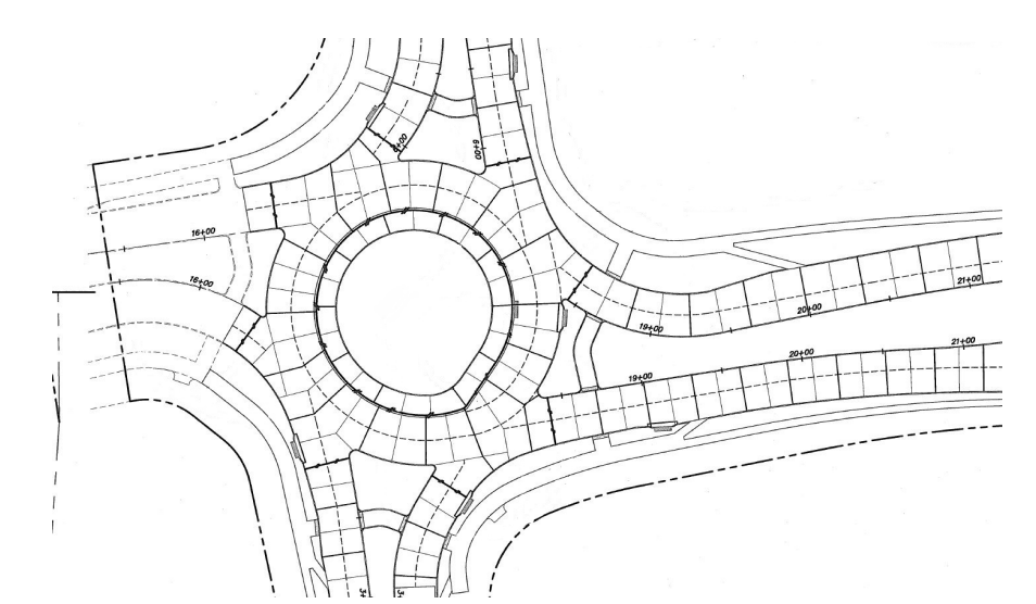
Figure 14-14: Example Pinwheel Jointing Pattern at a Multilane Roundabout
14.4.7.11 Bike Ramps
Bicycle ramps can be beneficial at single-lane roundabouts and are commonly considered at multilane roundabouts where on-street bicycle activity exists or is anticipated.
, Exhibit 10.25 and Exhibit 10.26 show an example of how bikes can transition from the on-street facility to the parkway facility and from the parkway facility to the on-street facility.
14.4.7.12 Pedestrian Crossing Devices
Based on the
publication, multilane pedestrian crossings at roundabouts and channelized turn lanes must have additional treatments that alert motorists to the presence of pedestrians or slow or stop traffic at those crosswalks. Additional treatments can consist of raised crosswalks, pedestrian actuated rectangular rapid flashing beacons (RRFB), pedestrian hybrid beacons (PHB), or a traffic control signal with a pedestrian signal head (R306.4.2).
The August 2023 Rules and Regulations update included additional clarification and guidance for pedestrian facilities consisting of:
- Detectable warning surfaces should be provided at all driveways where the driveways are controlled with stop or yield control (R205.7);
- The cross slope of the pedestrian access route within a crosswalk at a roundabout is permitted to be the same as the grade of the street that it crosses, up to a maximum slope of 5.0% (R302.5.2.2, R302.5.2.3, R302.5.2.4); and
- Where pedestrian crossing is not intended, the pedestrian circulation path shall be separated from the curb, crosswalk to crosswalk, with landscaping or other nonprepared surface 24 inches wide minimum (R306.4.1.1).