14.4.4 Design Parameters
The following design parameters and their associated values shall be documented and agreed upon by all relevant parties prior to a conceptual or schematic roundabout design. Advance determination of these parameters and values is beneficial to reduce the potential for future re-work of the roundabout design.
- Inscribed Circle Diameter, face of curb to face of curb (FOC-FOC);
- Circular ROW Footprint (ICD plus sidewalk and buffer strip, ft.);
- Design and Check Vehicle(s), per movement (i.e. If a larger vehicle is known to only make a right-turn at a given intersection, the remaining turning movements may be assigned a separate check vehicle) (see );
- Fastest Path Geometric Entry Speed, R1 (method: , Section 9.4);
- Fastest Path Entry/Circulating Speed Differential (V1 to V2) (see );
- Minimum Circulatory Cross Slope (%);
- Maximum Longitudinal Grade (% approach or circulating);
- Maximum Cross Slope (low side if circulatory roadway is tipped [i.e. tilted plane design]);
- Volume Range (sum of entering and conflicting volumes);
- Splitter Island Length (length will vary depending on if posted regulatory speed is less than or equal to 35 mph, or greater than 35 mph);
- Entry Curb Radius (near the yield line, ft.);
- Exit Curb Radius (ft.);
- View Angle (angle in degrees from a straight-ahead driver’s view) (see );
- Entry Width (see );
- Exit Width (see );
- Circulatory Roadway Width, FOC-FOC (ft.);
- Inner Circulatory Lane Width (ft.);
- Outer Circulatory Lane Width (ft.);
- Truck Apron Width (ft.) (see );
- Exit tangency (for path overlap check). Refer to , Exhibit A.18, and see RDM Section 14.4.5.6;
- Curb Offsets (ft.);
- Buffer Width (FOC to Sidewalk, ft.);
- Crosswalk Pedestrian Refuge Width (ft.);
- Crossing Accommodation (Traffic Control Devices and/or the use of raised crosswalks); and
- Maintenance of Traffic during construction (highway and/or lane closures).
, Section 10.7 provides justification for added emphasis of the following in multilane roundabout design:
- Geometric speed control;
- Avoidance of complicated lane configurations and use of single-lane entries and exits where the capacity trade-off is negligible;
- Development of natural parallel entry and exit paths;
- Provision of optimal approach lane markings; and
- Overhead signs for lane designation.
to
highlight ranges of common design considerations for various geometric parameters of roundabouts for the four different classifications.
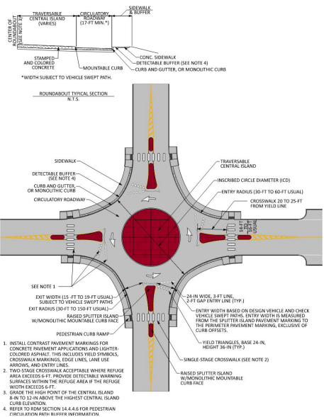
Figure 14-2: Mini-Roundabout Design Parameters
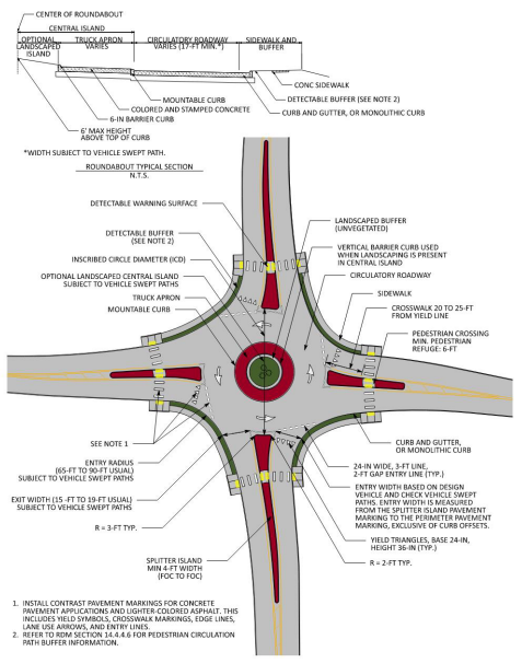
Figure 14-3: Compact Roundabout Design Parameters
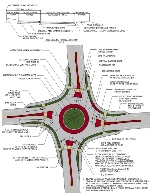
Figure 14-4: Single-Lane Roundabout Design Parameters
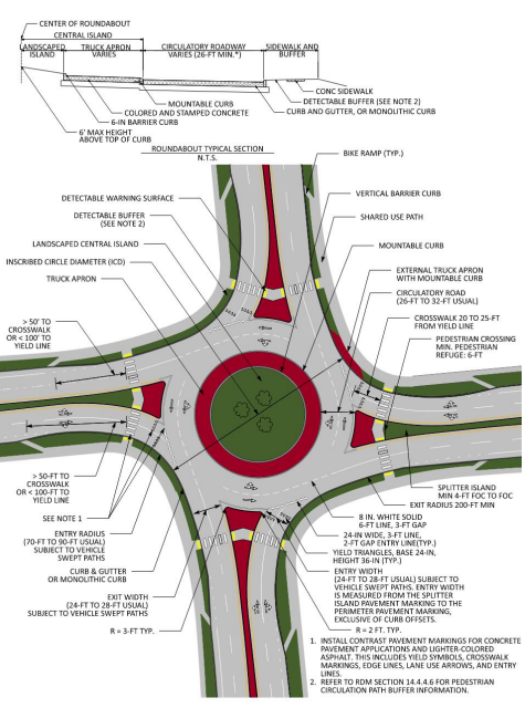
Figure 14-5: Multilane Roundabout Design Parameters
14.4.4.1 Entry and Exit Geometry
, Section 10.6.4 and Section 10.6.5 detail entry and exit design for roundabouts.
The entry width is measured from the center of the pavement marking that is adjacent to the splitter island to the center of the pavement marking adjacent to the exterior curb, or if a gutter section is present, the width is measured to the edge of the traveled way.
The design vehicle and check vehicle must be able to navigate the entry of a single-lane roundabout with a one-foot shy distance from the wheel path to the face of curb or edge of traveled way. When a WB-62TX is to be accommodated at a single-lane roundabout as the check vehicle, a wider entry width may be required due to the swept path of the rear tandem axle tires relative to the cab’s front tires.
At multilane roundabouts the entry width will depend on the design case. If stay-in-lane design is employed, then the resulting entry width will be greater than the typical straddle lane design entry width to accommodate the check vehicle in-lane while providing the necessary gore width between adjacent entry lanes. Individual lane widths for two-lane entries should remain in the 12-ft to 13-ft range. Maintaining trucks in-lane has safety consequences for other users including longer pedestrian crossings and higher in-lane speeds. Generally, promoting in-lane design for the design vehicle should be restricted to interchanges.
Exit design will rely heavily on single-lane or multilane designation, subsequent performance checks (fastest path and check vehicle), and the exit alignment that connects the roundabout to the adjacent roadway. Straighter exit paths provide ideal sight of the exit crosswalks, but exit speeds can increase, which places a greater emphasis on controlling entry speed.
14.4.4.2 Circulatory Roadway
For single-lane roundabouts, an 18-ft to 20-ft (face of curb to face of curb) circulatory roadway width is typical. For two-lane straddle-lane roundabouts, circulatory width is commonly in the range of 26-ft to 32-ft. For two-lane stay-in-lane design for trucks (“buffered lane design”), the circulatory width may be wider to accommodate the check vehicle being analyzed for both lanes in combination with the gore area separating the two circulatory lanes. Circulating lane widths should split the remaining circulatory roadway evenly.
14.4.4.3 Splitter Islands
, Section 10.6.1 and 10.14.2 discusses splitter island types and lengths. Splitter island design discussion can be found throughout
due to a splitter island’s influence on pedestrian and bicycle accommodation, speed control, deterring wrong-way driving, and space allocation for traffic control devices. Splitter islands may be bounded by full-height barrier curb, mountable curb, or a flush fully traversable painted area. The context of the intersection should dictate the elements chosen for the splitter island. The minimum length of a splitter island for low-speed urban design is 50-ft. See
for additional guidance for splitter islands at highspeed context roundabouts.
14.4.4.4 Truck Apron
, Section 10.5.2 discusses truck aprons. Guidance for truck apron sizing, materials, and even the relationship that truck aprons provide to maintenance can be found within
. It is important for the truck apron to have contrasting color and texture from the circulating pavement within the roundabout. This contrast allows drivers, especially during nighttime conditions, an increased ability to identify the limits of the circulatory roadway.
Consider the installation of yellow raised pavement markers spaced at 4-ft to 6-ft along the perimeter of the truck apron curb for mini-roundabouts to enhance nighttime visibility of the central island.
14.4.4.5 External Truck Apron
When performing the check vehicle performance checks, the usage of an external truck apron (a.k.a. “perimeter truck apron”) may be required to accommodate the wheel path of the check vehicle. The horizontal geometry of external truck aprons relies on the designer’s understanding of how to navigate the check vehicle through the respective movement (typically the right-turn but may also be required for through movements).
, Section 11.6 discusses the use of external truck aprons. The use of external truck aprons should be avoided, if possible, by incremental modifications to the approach and entry geometry, entry radius, exit geometry, and exit radius, such that the modifications still result in a design that is validated by the standard performance checks.
14.4.4.6 Pedestrian and Shared-Use Crossings
, Section 10.4.7 highlights the three basic types of pedestrian and bicycle crossings at roundabouts, angled, straight, and z-crossing. A best practice at roundabouts, especially where bike ramps are implemented, is the use of tactical directional indicators (TDIs). Refer to
, Section 10.4.3 for information regarding TDIs. Key considerations for pedestrian and bicycle crossing design at roundabouts consist of:
- Adequate space for pedestrian and bicycle refuge within the splitter islands;
- Bicycles that haul child trailers or cargo trailers may require additional width beyond the minimum prescribed six feet from face-of-curb to face-of-curb;
- Single-stage crossings where the refuge width in the splitter island is less than 6- ft and detectable warning surfaces (DWS) are omitted, versus a typical two-stage crossing where pedestrian refuge is accounted for between opposing directions of travel within the splitter island;
- Positioning and alignment of TDIs, when applicable; and
- 20-ft to 25-ft distance from the entry line adjacent to the nearest point of the designated crossing. Refer to .
Pedestrian circulation paths at roundabouts between crosswalks shall be separated from the curb with landscaping or other nonprepared detectable surface with a minimum width of 24 inches. Exception: If a curb-attached pedestrian circulation path is provided, it shall have a continuous and detectable vertical edge treatment along the street side of the path, from crosswalk to crosswalk. The bottom edge of the vertical edge treatment shall be 15 inches maximum above the pedestrian circulation path. Refer to Section R306.4.1.1. and R306.4.1.2. of the
, or latest version.