14.4.5 Performance Checks
The validation of a roundabout’s horizontal geometry is one of the most important steps in the design process. Roundabout performance checks should be completed prior to any vertical design or supplemental detailing of a roundabout.
, Chapter 9 highlights the various current industry standard performance checks associated with fastest path speeds, sight distance, view angles, vehicle path alignments, design and check vehicles, and bicycle and pedestrian wayfinding and crossing assessment. Appendix A of
outlines performance check techniques. Performance checks completed in CAD software are required to remain a part of the project’s design files throughout the project life cycle, including postconstruction, in case an audit of the roundabout occurs after the roundabout is constructed.
14.4.5.1 Documentation Requirements
A roundabout design performance checks package is required. The documentation should be compiled in a series of design check diagrams as follows:
Series 1 –
Overview and Horizontal Design - A dimensioned general layout drawing showing:- Inscribed circle diameter, circulatory roadway width, entry and exit widths, splitter island lengths, and truck apron widths;
- Pedestrian crossing locations/width, composition, raised/flush, markings, when applicable;
- Bicycle lane/approach & termination point, when applicable;
- A typical cross-section of the roundabout’s central island (mounded), roadway and truck apron compositions and integration, widths, slopes, and curb standards;
- Location of nearest entrances from the inscribed circle diameter and the nature of the land use; and
- Proximity of roundabout to traffic signal or other intersections.
Series 2 -
Geometric design speed (‘fast path’) diagrams for each approach, entry, circulating, and exit are required. Roundabouts must be designed to promote geometric speed control per theoretical fastest path speeds in accordance with
, Section 9.4 and
. Left offset of the approach alignment increases the space for the approach curve to be well-developed for entry speed reduction. Geometric entry speeds, measured according to
, must be less than 25 mph along the fastest through movement path for single-lane roundabouts and less than 28 mph for the fastest through path for multilane roundabout entries. Approach roadway design speeds and fastest theoretical paths are to be shown. Fast path radii and the range of corresponding speeds based on a (+)2.0% cross slope and (- )2.0% cross slope are to be annotated on the design checks submittal Series 2 diagrams.Series 3 -
Truck swept-path diagrams are to be developed using AutoTURN®, Vehicle Tracking, or similar software, with depiction of the design and check vehicle(s) for all of the anticipated turning movements. Design and check vehicles will validate the width of lanes and the circulatory roadway, e.g., S-BUS-40 or CITYBUS. The check vehicle shall validate the width of the central island truck apron and entry and exit widths using a 1-ft shy distance from face of curb (FOC) to the vehicle wheels. The truck cab of a design and check vehicle will typically stay on the circulatory roadway when running swept-path analysis with all tires remaining at least 1-ft from the face of curb.Series 4 –
Stopping sight, intersection sight and view angle diagrams accounting for both vertical approach grades and horizontal alignments. Sight distances must account for driver eye height and height of objects. This is for the purpose of user safety and to establish limits to planting scheme/landscaping for the mounded central island and splitter islands. Refer to
, Section 9.5.Series 5 –
Ancillary elements diagrams include light pole locations and traffic control devices such as signing and pavement markings (refer to the
). These elements are generally developed after schematic design; however, with multilane roundabouts, it is necessary to design markings at the concept or schematic stage to validate the use of exclusive lanes and spiraled geometry.14.4.5.2 Geometric Speed Control (Fastest Path Speed Measurement)
, Section 9.4.1 and Appendix A.1 covers the assessment of speed control for a roundabout’s horizontal geometry. Section 9.4.2 of
outlines the process for developing fastest path alignments using the spline technique. Key considerations for fastest path speed assessment for roundabouts consist of:
- Correct placement of node points to develop the associated spline;
- Using Control Points (MicroStation) as a method for creating the spline within CAD software;
- Using the correct offset dimension for the center of vehicle location relative to curbs or pavement markings;
- Producing a spline that is located within 5.0-ft to 5.1-ft of the controlling offset feature (face of curb or pavement marking), or 3.0-ft to 3.1-ft where opposing traffic adjacent to the roadway centerline is separated by 5-ft or greater;
- Avoiding the addition of node points beyond the typical nine nodes for a through movement, seven nodes for a right-turn movement, and nine nodes for a left-turn movement;
- Adjusting node points along the 165-ft, 215-ft, or 265-ft offset arcs from the ICD when creating a spline that does not cross the minimum 5.0-ft offset along the approach or exit geometry of the roundabout;
- Maintaining less than a maximum differential between V1 to V2 and V1 to V4 of 10 mph;
- Use of a maximum allowable fastest path entry speed, V1, to a value of 28 mph for a multilane entry design;
- Use a consistent 70-ft arc length along the spline when calculating the corresponding R-value; and
- Comparing R2 values on opposite sides of the central island. Unbalanced R2 values can be an indicator that the ICD chosen for the roundabout design may not be optimized and should be shifted in the direction of the higher R2 value to provide enhanced and balanced speed control.
provides a graphical representation of the corresponding theoretical maximum fastest path speed alignments for a left-turn (R4/V4), through movement (R1/V1, R2/V2, R3/V3), and a right-turn (R5/V5).
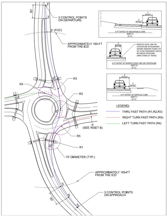
Figure 14-6: Geometric Speed Control Fastest Path Performance Design Checks
14.4.5.3 Path Overlap
Path overlap is a detrimental condition that can arise from inadequate horizontal geometry of multilane roundabout entries and exits, as discussed in
, Section 9.6. Providing tangency to adjacent entry and exit lanes has emerged as an important feature of multilane design to discourage vehicle lane changing within the circulating/conflicting conflict zone areas of a roundabout.
visualizes the method for checking path overlap. The amount of tangent to avoid entry path overlap and exit path overlap between point A to point B and point B to point C, respectively, is 30-ft to 50-ft and 40-ft to 60- ft. One check of adequate entry geometry is for the tangent point at point A to be located within 5-ft of the entry yield line. Additional tangency beyond 5-ft prior to the entry line should be avoided so the speed-controlling entry radius is not shifted too far in advance of the typical crosswalk location.
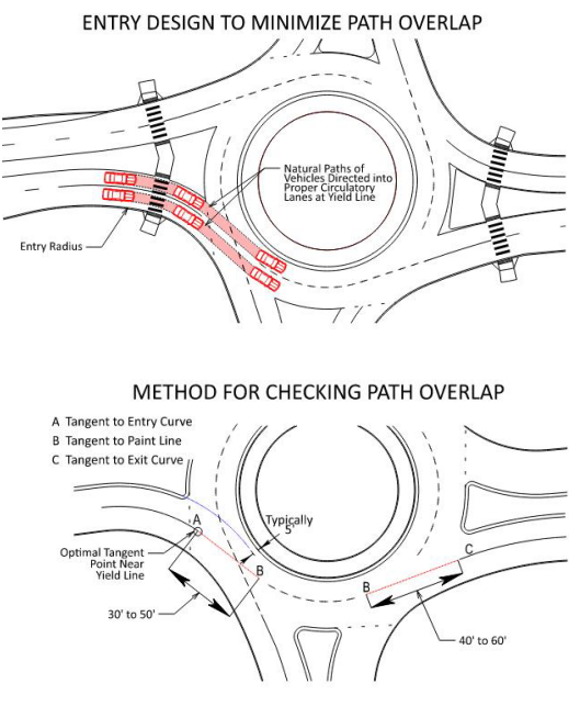
Figure 14-7: Natural Path Performance Design Checks
14.4.5.4 Design and Check Vehicles
, Section 9.7 covers the topic of design vehicles. The largest anticipated non-articulated vehicle that is needed to be fully accommodated in the circulating roadway within the roundabout (the “design vehicle”), and the largest anticipated articulated vehicle subject to use a given roundabout (the “check vehicle”) are key roundabout design parameters. Typical design vehicles are the largest local jurisdiction fire department apparatus or a city bus. An additional check vehicle that includes articulation, such as a WB-40, WB-62TX, or WB-67, should be analyzed in properly sizing entry widths, circulatory roadway widths, truck apron widths, exit widths, and determining the final location of proposed curbing within and adjacent to a given roundabout.
The selection of the design vehicle and the check vehicle to navigate the intersection throughout the life cycle of the intersection is necessary prior to preliminary design. Consideration should be given for individual movements at an intersection. The design vehicle and check vehicle may only need to make thru movements and may not need to make left or right-turn movements on or off the major roadway. Adjacent land use, trip generators, and local and regional routing may factor into the verification of movements of the check vehicle on a case-by-case basis. The selection of the appropriate vehicles should be vetted with TxDOT staff, and possibly with local agency staff, local stakeholders, and potential permitted load routing.
, Chapter 9 and Appendix A.4 outlines vehicle performance checks for design vehicles and check vehicles.
Key considerations for design vehicles and check vehicles at roundabouts consist of:
- The appropriate design case- straddle lanes or stay-in-lane (refer to , Section 9.7.1 for more information);
- The width of outer lane or inner lane curb offsets;
- If curb and gutter is proposed, the dimensions of curb and gutter are important in keeping design and check vehicle wheel paths off the gutter pan;
- Allowance of a shy distance between the vehicle’s outer wheel path and face of curb (or edge of traveled way);
- Analyzing left-turning articulated vehicles within the inner lane of a multilane circulatory to determine the appropriate truck apron width;
- Selection of the largest anticipated vehicle (i.e., the check vehicle) that may need to navigate the roundabout. OSOWs would be classified as a check vehicle if determined to be needed along the route where a proposed roundabout is being considered. For the check vehicle, external truck aprons may be used to facilitate the proper accommodation of an OSOW to avoid widening travel lanes adjacent to and within the roundabout; and
- The use of a WB-62TX check vehicle in lieu of a WB-67 or WB-62 check vehicle. WB-62TX represents a WB-62 with a 53- ft trailer instead of the WB-62’s 48-ft trailer. Given that most tractor-trailer combinations will haul 53 ft trailers with their rear tandems moved, it is appropriate to use the WB-62TX at locations other than interstate ramp terminals or near truck terminal locations.
shows common design and check vehicle specifications based on
for a CITY-BUS and a WB-67. The WB-62TX designation, although not an official designation by AASHTO, is a common tractor-trailer configuration in Texas and is recommended to be used as a check vehicle where a WB-67 configuration is not anticipated.
of this manual has additional information on Design and Control Vehicles.
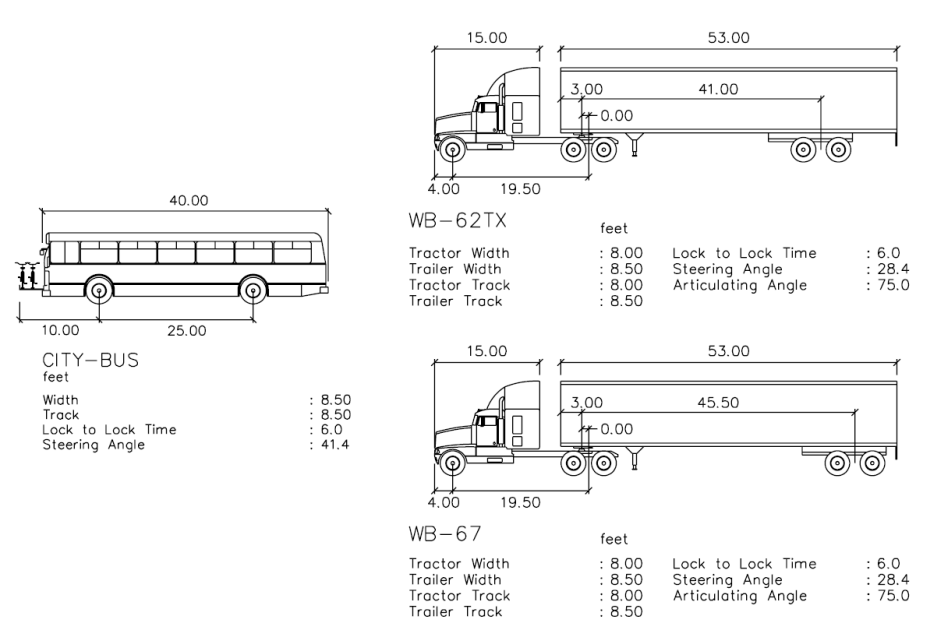
Figure 14-8: Design Vehicle and Check Vehicle Templates
14.4.5.5 Truck Accommodation at Multilane Roundabouts
Straddle lane design is presumed unless it can be shown that a given intersection is anticipated to accommodate a significant amount of daily or peak period truck traffic. If an intersection is anticipated to have 120 trucks per hour, or more, (one truck every 30 seconds) on a given approach, stay-in-lane design is recommended to be implemented. Contexts for stay-in-lane design will be roundabouts proposed at interchanges, near common OSOW facilities and freight trip generators.
The need for stay-in-lane design increases at roundabouts that are anticipated to experience near- or at-capacity conditions in the peak periods. This is due to the additional time gap needed for large trucks to be able to enter safely into the circulatory while yielding to circulating/conflicting vehicles. A stay-in-lane design in this situation allows passenger vehicles to accept smaller gaps in traffic and proceed through the roundabout while the large truck waits for an extended gap in traffic.
14.4.5.6 View Angle
View angle is the angle created by a driver yielding at the entry line while looking to their left to identify oncoming vehicles that will conflict with their entry path. As the angle that a driver is required to turn their head to identify oncoming traffic increases, vision and detection of potential conflicts becomes increasingly difficult. This may especially be the case with drivers with chronic neck pain, injuries, or elderly drivers. View angle is also a factor with large trucks, whereby the side window placement is commonly a constraint for sight to the left at acute angles.
, Exhibit A.16 and
depict the arrangement of vehicles for angle of visibility checks. If an oncoming vehicle’s location crosses out of the 105- degree cone of vision for this visibility-to-the-left performance check, drivers will not be able to move close to the yield line for normal sight of oncoming traffic to the left. In such cases, the approach and entry geometry must be modified to improve the view angle. Skewed intersections and right-turn yielding bypass lanes are typical examples where view angle performance checks are vital to providing visibility-to-the-left.
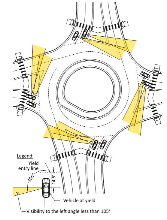
Figure 14-9: View Angle Example
14.4.5.7 Sight Distance and Visibility
, Section 9.5 documents the relevant sight distance checks for roundabouts. Stopping sight distance, intersection sight distance, and decision sight distance are all relevant to roundabout geometric design. Key considerations for adequate sight distance at roundabouts consist of:
- Proper grading and clear zones within the central landscaped island of the roundabout to accommodate the circulatory roadway’s stopping sight distance requirement (refer to , Exhibit 14.9);
- Avoidance of perimeter landscaping, signage, street furniture, franchise utility equipment, and other appurtenances that may restrict sight distance;
- Avoidance of splitter island treatments that may restrict stopping sight distance, especially for approach geometries of skewed intersections and offset left designs. Trees, vertical walls, and franchise utility equipment are a few common obstructions that should be avoided in a splitter island within 50- ft of a roundabout’s ICD; and
- Avoidance of an abundance of sight distance. When the central landscaped island of a roundabout is graded flat or lacking berm height, it allows approaching motorists to see through a roundabout. Similarly, if the approaching splitter island and perimeter quadrant to the left of an approaching driver is vacant, it can allow for an approaching motorist to identify the absence of potential circulating/conflicting traffic upon their arrival at the entry of the roundabout. This abundance of sight distance can result in drivers maintaining faster speeds as they recognize no conflicts will be present upon their arrival at a roundabout. Providing restrictive sight elements outside of sight distance envelopes can reinforce speed reduction for approach drivers resulting in safer driving conditions at the crosswalk and entry of a roundabout.