14.4.6 Special Considerations
To supplement
, the following roundabout design considerations are presented to increase design flexibility for complicated design context of roundabouts in Texas.
14.4.6.1 Oversized and Overweight Vehicles
Oversized and overweight vehicles are common on Texas roads. Due to the presence of wind turbine tower trailers, heavy construction equipment trailers, and other large transport trucks, it can become necessary to specifically modify a roundabout design to accommodate an OSOW. Coordination should take place between the intersection location’s TxDOT Area Office and the engineer-of-record to determine if permitted loads are present at the subject intersection, and if so, the specifications of the largest anticipated vehicle.
, Section 10.5.4 discusses the design of roundabouts for OSOWs.
14.4.6.2 High-speed or Intermediate Speed Approach Design
Note for the general purposes of superelevation methodologies, intermediate speeds are classified as between 50-60 mph (see
). Roundabouts installed in these contexts require recognition of the human factors needs of the driver to detect, recognize, and react to the presence of a roundabout while approaching the intersection at a higher rate of speed.
The primary safety concern in intermediate/high-speed context is clarity of the driving situation, that is, to make drivers aware of the roundabout with ample distance to comfortably decelerate to the appropriate speed. Therefore, designs should abide by these principles:
- Provide the desirable forward stopping sight distance of the entry point based on approach operating speed;
- Align approach roadways and set vertical profiles to make the central island conspicuous and mound the central island 3.5-ft. to 6-ft;
- Splitter islands should extend upstream of the yield line to the point at which entering drivers are expected to begin decelerating. A minimum length of 200- ft is recommended for high-speed approaches;
- It is typical for the approach treatment to extend the project limits to greater than 500-ft from the center of the roundabout. Approach curves should be gentle, become successively smaller and should be sized based on the design speed and expected speed change of 15 to 20 mph per successive horizontal curve; and
- The use of a tangent between horizontal curves is recommended unless the curves have large radii and there is no required superelevation of either curve. A common tangent length is 100ft. The use of a tangent has been shown to eliminate truck rollovers where curve radius and curve length are relatively small in a high-speed context. Refer to the on TxDOT.gov for additional information.
For approaches to roundabouts see
for appropriate superelevation methods.
Guidance provided in
, Section 10.14 combined with
aids in designing splitter island length, horizontal curves, and superelevation to treat roundabouts in an intermediate/high-speed context.
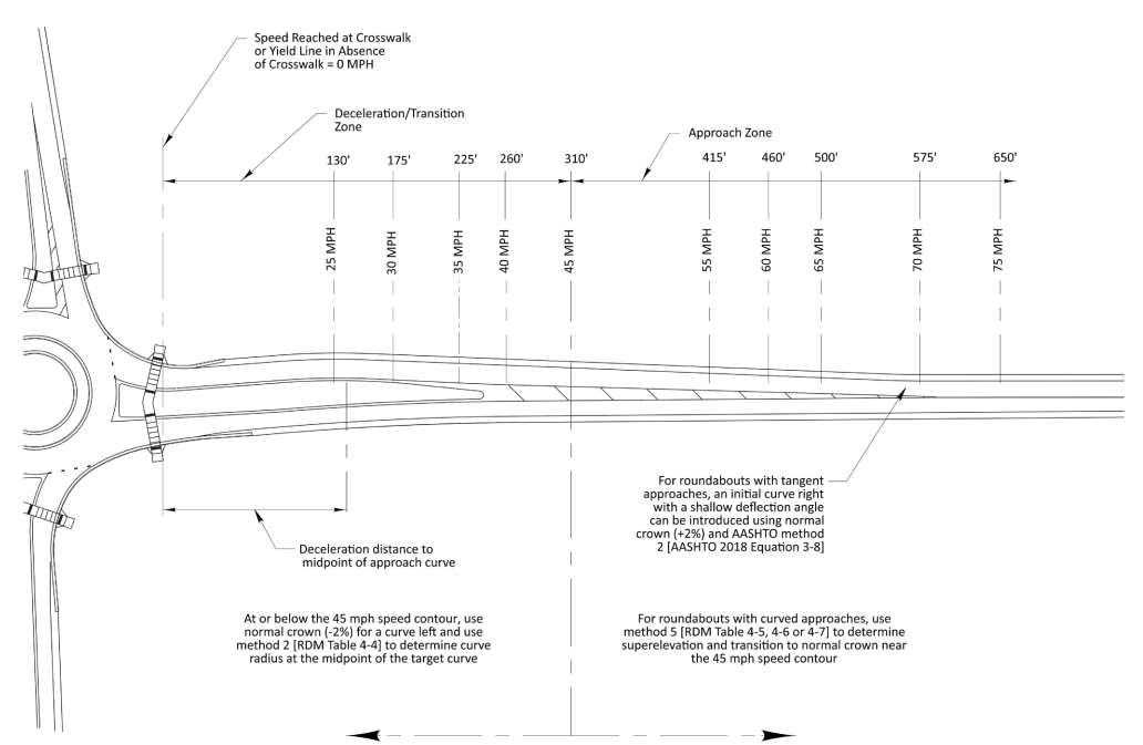
Figure 14-10: High-Speed Approach Design Approach and Deceleration Zones
14.4.6.3 Spiral Design
Spiral circulatory geometry is commonly used when a dedicated left-turn lane is implemented at a multilane roundabout.
shows an example of a spiraled movement. Spirals can also be applied for any 2x1 lane configuration roundabout where the single circulating lane spirals to the portion of the roundabout where a resulting two lanes are located within the circulatory. Benefits of using spirals in roundabouts consist of:
- Guiding the circulating vehicle to the outer lane of the two-lane circulatory;
- Where adjacent driveways are located close to the roundabout, or a heavy right-turn movement is common at the adjacent downstream intersection;
- Reduces the size of the conflict zone, the area where entering vehicles interact with circulating/conflicting vehicles; and
- Reinforce yield behavior for the outer lane entering driver that is yielding at the two-lane entry because the spiral makes it more apparent that the circulating vehicle will cross the entry path of this entering lane.
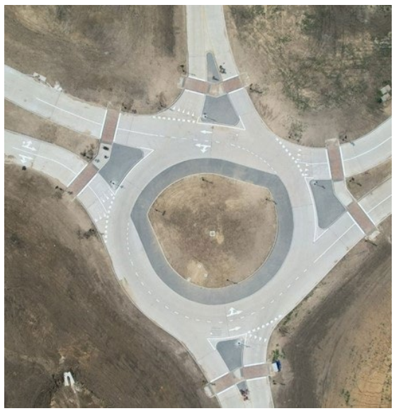
Figure 14-11: Spiral Design Example
Source: Kyle Kruppa
14.4.6.4 Buffered Lane Design
The concept of buffered lane design has emerged from discussions in the U.S. of how to adapt turbo roundabout design to conventional U.S. multilane roundabout design. Buffered lane design is also emerging as a retrofit solution where constructed roundabouts may have excessive ICDs and/or circulatory widths.
The benefits of buffered lane roundabouts are evident with improved lane discipline for passenger vehicles, reduced vehicle speeds and failure-to-yield conflicts, while also providing lane discipline for articulated trucks. Where existing multilane roundabouts have been built with a surplus of circulatory width, buffered lane design represents a low-cost solution to narrow circulating lanes which in turn enhances speed reduction and lane discipline without having to consider full-depth reconstruction as part of a safety improvement.
Applying buffered lane design to initial installation is done more deliberately while upholding the basic principles of ICD size, geometric speed control, and approach alignment.
shows an example of a buffered lane design roundabout.
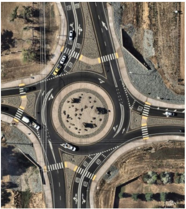
Figure 14-12: Buffered Lane Example (applied as a retrofit without moving curbs)
14.4.6.5 Turbo Roundabouts
By definition, a turbo roundabout includes a radial entry and exit design, employs orbiting geometry within the circulatory to facilitate the origin-destination path through the roundabout, and makes use of raised dividers to channelize vehicles to enforce in-lane driving. Implementation of turbo roundabouts is in its infancy stage in the U.S. since only a handful of turbo roundabouts have been built in the U.S. Designers must exercise caution when selecting this type of roundabout. Refer to Section 10.7.8 in
for additional information regarding turbo roundabouts. An example of a constructed turbo roundabout in the U.S. is shown in
.
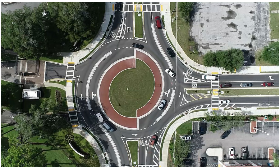
Figure 14-13: Example Turbo Roundabout (Jacksonville, FL)
14.4.6.6 Expandable Design
Interim and ultimate lane configuration roundabout analysis may result in a preferred method of using future expandable design. If within the operational analysis a roundabout is shown to benefit from a reduced lane configuration on opening day for the first 10 to 15 years of its existence, then expandable design should be considered. Reducing the number of entry lanes on a given approach will result in less conflict points, shorter crossing distances for pedestrians and bicyclists, and provide for safer operations.
, Section 10.8 discusses the use of expandable design, including commentary on the advantages and disadvantages of expanding outward versus expanding inward.
14.4.6.7 Railroads and Preemption
, Section 12.7 provides guidance on roundabouts near rail crossings. Roundabouts with at-grade rail crossings nearby or within the roundabout have been constructed at many locations in the U.S., including downtown Daingerfield, TX. The decision of whether to install crossing gates at a roundabout may be considered early in the planning or design process. Early and up-front coordination is highly recommended with the governing railroad agency if a roundabout is proposed near an at-grade rail crossing. Risk analysis, traffic queue calculations, train crossing frequency and duration, and proximity of the roundabout to the rail crossing are important factors when considering a potential roundabout installation in this type of context.
14.4.6.8 Median and Access Management Benefits and Considerations
Various topics arise when considering the effect of roundabouts and access management. Roundabout corridors can replace median-opening cross-access along an undivided or divided roadway. Motorists can make use of U-turn movements at a roundabout to facilitate what would previously be a left-turn movement to access a property on the opposite side of the street.
A corridor of roundabouts combined with continuous raised medians provides amplified safety benefits by eliminating high severity crash types such as head-on and right-angle or side-impact collisions. Roundabouts provide U-turns for all vehicle types at low speeds, eliminating the risks of mid-block left-turns and U-turns across opposing high-speed traffic. Median width can thereby often be reduced since mid-block turning movements are prohibited. This strategy is called “wide nodes and narrow roads”. Severe crash risks are reduced within the narrowed mid-block roadway section and at the intersections. Roundabout spacing in this type of corridor is important to consider to limit the distance required for a vehicle to make a U-turn to access adjacent property.
Driveway locations relative to a roundabout can typically be moved closer to the intersection with a roundabout, as compared to a conventional traffic signal installation, due to shorter queue lengths. Other factors influencing the location of a driveway relative to a roundabout consist of:
- The location of a bike ramp or crosswalk that may conflict with the driveway;
- A queue spillback analysis at the entry of a roundabout;
- The frequency of left-turns wanting access to the driveway; and
- The resulting storage length for a yielding right-turn bypass lane.