23.3 TCP Design Considerations
23.3.1 Duration
Work durations are defined by the TMUTCD and by the
. TCP of 3 days or less may be implemented by the contractor using the
. An engineered (signed & sealed) traffic control design shall be required and provided to the contractor in the construction plans for Long Term Stationary work that is for an expressway/freeway. Unique project conditions, such as detours of major arterials or rapid bridge replacement involving higher risk to the travelling public, may justify TCP plans of 3 days or less to be designed as part of the construction plans.
23.3.2 Cross Sectional Elements
23.3.2.1 Typical Sections
Typical sections for TCP are generally much more restrictive than permanent typical sections. Cross slopes may vary greatly depending on the nature of the existing, temporary, or permanent pavement upon which the traffic is being maneuvered. Lane and shoulder widths are allowed to decrease and edge conditions are allowed to be more aggressive before protection by concrete barrier is required, as described below.
23.3.2.2 Lane Widths
Typically, lane widths for TCP plans should not be less than one foot narrower than the lane widths for the permanent design. However, if the permanent lane width is already under a design exception, the TCP lane width should not be decreased any further. Alternatively, in cases where the desired minimum lane width is not feasible, for instance to temporarily pass traffic through a narrow obstruction, a narrower lane width may be considered using engineering judgement, provided the alignment is straight through the entire approach and departure of the obstructions. In these extreme cases, lanes should be striped with a continuous solid white line to prohibit lane changes.
23.3.2.3 Shoulder Widths
Typically, a shoulder width of two feet or greater is desirable to reduce the probability that traffic control devices or concrete barrier will be struck, as well as to minimize the chance that debris collected against a concrete barrier will obscure the temporary edge striping. However, in extreme cases the shoulder width could be reduced to zero if there are no other options.
In areas where traffic is constrained by concrete barrier for a considerable distance, safety pullouts for disabled vehicles should be provided at regular intervals based on engineering judgement. These areas should be clearly signed that they are for emergencies only.
23.3.3 Pedestrian and Bicycle Requirements
According to the
Section 6A.01, road users include not only motorists, but bicyclists, pedestrians, and persons with disabilities in accordance with the
, Title II, Paragraph 35.130.
The requirements in the
are compulsory, therefore, a TCP design should consider the needs and control of these users in every phase of construction. Safe and effective paths should be maintained not only for instances where pedestrian or bicycle facilities currently exist, but also at locations where accommodations may not currently exist but there is known use by pedestrians or bicyclists.
The designer should perform an assessment of the existing facilities for pedestrians and cyclists – including widths, grades, surface conditions, pavement markings, signing, anticipated usage, and access to these facilities. The designer should document the impact assessment in the DSR.
23.3.3.1 Pedestrians
If the TCP zone affects the movement of pedestrians, the designer should provide for adequate pedestrian access and walkways. If the temporary traffic control zone affects an accessible and detectable pedestrian facility, the accessibility and detectability shall be maintained along the alternate pedestrian route (
, Section 6D.01 Pedestrian Considerations, 04). Refer to the
for additional information on accommodations for the visually impaired.
In accommodating pedestrians, the following principles should be applied, addressed, and incorporated into the TCP design:
- Do not lead pedestrians into hazardous environments or conflicts with public traffic, construction vehicles, equipment, or operations.
- Use existing intersection corners and crosswalks when directing pedestrians across a roadway. An existing marked mid-block crossing may be used to shorten pedestrian routes.
- Provide a convenient, contiguous pathway that is equivalent to the existing level of pedestrian accessibility.
- Minimize out-of-direction travel for pedestrians.
- Sign the closure of a pedestrian route in a minimum of two locations:
- In advance of the closure point at the nearest alternate crossing or diversion point; and
- At the closure point itself.
- Avoid having a pedestrian route double-back on itself. Pedestrians are not likely to walk one block beyond the closure to the next crossing and then one block back on the other side of the road. They will likely cross before the work zone impact (if visible), or midblock – which may be unsafe or leave the pedestrian within the work area.
- Confirm whether visually impaired pedestrians can be expected in the work zone. Techniques include:
- Personal investigations and/or collecting manual counts; and
- Coordinate with local agency/organization sources, and other stakeholders.
23.3.3.2 Bicycles
Designers should investigate existing conditions within the limits of their project to determine what accommodations, if any, need to be established for bicycles. Some of these conditions include:
Closure of Existing Shoulders, Sidewalks, Bike Lanes or Shared-Use Paths
: The TCP design should provide temporary facilities or pathways that allow for safe, efficient bicycle travel through or around the work zone. Long term TCP designs often leave minimal operational widths for vehicles with little to no shoulder in a corridor that may commonly be used by bicycles even if there is no dedicated bicycle lane. Consider alternative bicycle routes when 4-ft or more of pavement outside of the vehicular lane is not feasible. Shared use of the roadway by both motorists and bicyclists may be considered, but it generally not recommended, especially for high-speed traffic.Urban/Urban Core/Suburban/Rural Town Intersections
: The scope of work often includes all four corners of an intersection and can intrude into the shoulder/bike lane. In some of these environments, viable detours or space for adequate temporary facilities may be limited. If measures can be deployed to ensure a speed reduced to 35 or below through the work zone, use of a shared roadway condition may be a measure for accommodating bicyclists.Construction Details
: Where applicable, TCP Plans must provide enough detail to safely accommodate bicycle traffic within the work zone. Bicycle-specific details may be included on separate plan sheets, depending on the level of complexity at each location where special bicycle channelization is needed. Include details such as:
- Bicycle traffic routes;
- Bicycle channelizing devices;
- Bicycle-specific temporary signs;
- Cross sections at critical locations or “pinch points” where precise placement of traffic control devices (TCD) is vital; and
- Temporary surfacing material and markings.
Occasionally neither on-site roadway widths nor local detours are available. In these cases, innovative means of transporting bicycles through the construction area should be considered and weighed against traditional measures. Partnerships with public transit or private shuttle services have been used in the past to maintain acceptable levels of bicycle mobility. Consider temporary bus/shuttle stops, information kiosks, “hotline” phone numbers, etc., to provide an effective transportation means for cyclists.
23.3.4 Property Access Requirements
Construction at property access points, such as residential and commercial driveways, that do not have any alternate access points away from the construction, should be staged so that the property owner always has the ability to enter and leave their property by vehicle. The designer should provide the contractor with details for how to stage construction at these access points, for instance doing half a side at a time, even if it reduces the width to the point where only one vehicle can pass through at a time.
If maintaining access to a property during construction is extremely problematic then the contractor will need to coordinate with the property owner to implement an agreed plan in writing for offsite parking, pedestrian access, service and fire vehicle access, or total temporary access denial.
23.3.5 Temporary Geometry Requirements
The geometric alignment of the TCP should be similar to the geometric alignment of permanent design. Section 6B.01 of the
states: “The basic safety principles governing the design of permanent roadways and roadsides should also govern the design of TCP zones. The goal should be to route road users through such zones using roadway geometrics, roadside features, and TCP devices as nearly as possible comparable to those for normal highway situations.”
23.3.5.1 Horizontal Geometry
Horizontal geometrics for short duration, short term stationary, and intermediate term stationary traffic control alignments may be implemented using the diagrams in the
and
. These implementations are not likely to involve the temporary detour pavement, pavement markings, or concrete barriers that are often required for long term stationary alignments.
For long term stationary alignments, lateral shifts in the traffic not more than one lane width in distance may be designed using shift tapers. However, for traffic shifts greater than one lane width, or for complex alignment, designed horizontal curvature is preferable.
TCP horizontal curves should be designed so that the side forces on the vehicles do not exceed the recommended maximum safe side forces for various design speeds (refer to the Maximum f column of Table 3-7 of the 2018
).
The TCP design may require a shift of alignment of traffic in locations other than straight, normally-crowned roadway. The designer should consider the cross slope of the pavement upon which the curves are designed, and whether or not the cross slope is towards or against the direction of the curvature. Minimum radii for combinations of TCP design speed and cross slope are shown in
below.
TCP Design Speed | |||||||||
Cross Slope | f max 20% | f max 18% | f max 16% | f max 15% | f max 14% | f max 13% | f max 12% | f max 11% | f max 10% |
30 mph R (ft) | 35 mph R (ft) | 40 mph R (ft) | 45 mph R (ft) | 50 mph R (ft) | 55 mph R (ft) | 60 mph R (ft) | 65 mph R (ft) | 70 mph R (ft) | |
-8% | 500 | 817 | 1,334 | 1,929 | 2,778 | 4,034 | 6,000 | 9,389 | 16,334 |
-7% | 462 | 743 | 1,186 | 1,688 | 2,381 | 3,362 | 4,800 | 7,042 | 10,889 |
-6% | 429 | 681 | 1,067 | 1,500 | 2,084 | 2,881 | 4,000 | 5,634 | 8,167 |
-5% | 400 | 629 | 970 | 1,350 | 1,852 | 2,521 | 3,429 | 4,695 | 6,534 |
-4% | 375 | 584 | 889 | 1,228 | 1,667 | 2,241 | 3,000 | 4,024 | 5,445 |
-3% | 353 | 545 | 821 | 1,125 | 1,516 | 2,017 | 2,667 | 3,521 | 4,667 |
-2% | 334 | 511 | 762 | 1,039 | 1,389 | 1,834 | 2,400 | 3,130 | 4,084 |
-1% | 316 | 481 | 712 | 965 | 1,283 | 1,681 | 2,182 | 2,817 | 3,630 |
0% | 300 | 454 | 667 | 900 | 1,191 | 1,552 | 2,000 | 2,561 | 3,267 |
1% | 286 | 430 | 628 | 844 | 1,112 | 1,441 | 1,847 | 2,348 | 2,970 |
2% | 273 | 409 | 593 | 795 | 1,042 | 1,345 | 1,715 | 2,167 | 2,723 |
3% | 261 | 389 | 562 | 750 | 981 | 1,261 | 1,600 | 2012 | 2,513 |
4% | 250 | 372 | 534 | 711 | 926 | 1,187 | 1,500 | 1,878 | 2,334 |
5% | 240 | 356 | 508 | 675 | 878 | 1,121 | 1,412 | 1,761 | 2,178 |
6% | 231 | 341 | 485 | 643 | 834 | 1,062 | 1,334 | 1,657 | 2,042 |
7% | 223 | 327 | 464 | 614 | 794 | 1,009 | 1,264 | 1,565 | 1,922 |
8% | 215 | 315 | 445 | 587 | 758 | 961 | 1,200 | 1,483 | 1,815 |
Note that these TCP radii match the radii found in Table 3-13 Minimum Radii and Superelevation for Low-Speed Streets in Urban Areas,
, which follows Superelevation Distribution Method 2. However, this table has been developed to include higher TCP design speeds across a higher range of existing cross slopes using the formula V2/15R = e + f. The designer also has the option of using a more conservative superelevation methodology (see
).
should not be used for permanent design of high-speed facilities. Permanent conditions must use the superelevation methodology indicated in
).
23.3.5.2 Design Examples:
23.3.5.2.1 Example 1:
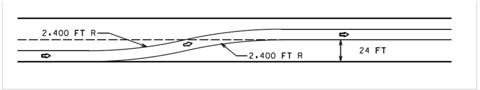
The TCP designer needs to lay out a long-term shift of traffic across a 2% normal crown where the work zone design speed is 60 mph and the traffic is being shifted laterally by 24-ft. A shift taper based on WS/2 would require 720-ft with a 1.9 degree diverging angle, while a reverse curve using a 2,400-ft radius could be accomplished in 479-ft. In this case the added complexity of laying out a reverse curve in construction may be justified in order to save nearly 250-ft of transition distance as well as resulting in smoother navigation of vehicles through the lateral shift.
 |
23.3.5.2.2 Example 2:
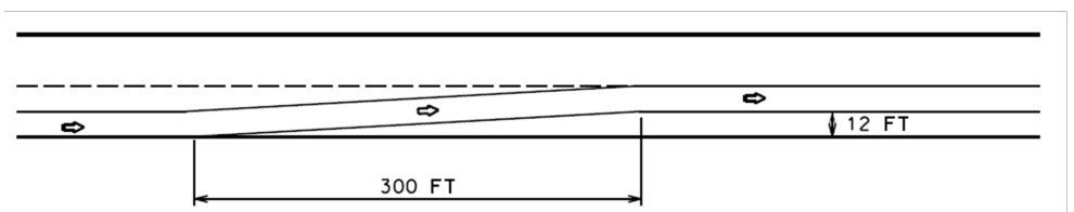
A TCP designer needs to lay out a long-term shift of traffic across a 2% normal crown where the work zone design speed is 50 mph and the traffic is being shifted laterally by 12-ft. A shift taper based on WS/2 should be adequate in this case resulting in a diverging angle of 2.3 degrees and a shift length of 300-ft, through which a vehicle may naturally spiral within the width of the lane as it navigates. Although a reverse curve using a 1,389-ft radius may be smoother and produce a slightly shorter shift length of 258-ft, the distance saved is probably not worth the additional complexity required for construction layout.
 |
23.3.5.2.3 Example 3:
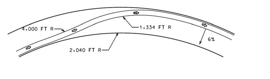
The TCP designer needs to lay out a long-term shift of traffic on existing or new pavement through a horizontal curve with a 6% superelevation where the work zone design speed is 60 mph. In this case the vehicle path could be curved opposite the direction of the the cross slope with a radius of 4,000-ft without exceeding the maximum side force. A tangent should be avoided as this might cause the driver to speed up. The vehicle path could be brought back into the horizontal curve with a 1,334-ft radius in the direction of superelevation slope. This would accomplish the shift in the minimum possible distance.
 |
23.3.5.3 Vertical Geometry
The K values of sag and crest vertical curves in a TCP design should use the same requirements as permanent design as specified in
. If these K values cannot be reasonably achieved, the designer should consider a further reduction in the work zone speed limit for the specific construction phase or location involved to shorten the stopping sight distance. This reduced speed should be clearly posted as an advisory sign.
23.3.6 Temporary Pavement Structure Requirements
Temporary detours and widening required for a TCP design should follow the guidance shown in TxDOT’s
, Section 5. Prior to designing an alignment using temporary pavement, the designer should perform a cost analysis between the use of temporary pavement (including any temporary drainage, embankment, and structures required) and alternate construction phasing that takes advantage of using either existing or permanent pavement.
23.3.7 Temporary Drainage Requirements
Stormwater drainage for temporary conditions during construction where the permanent drainage has not yet been constructed or connected should be designed using the guidance in TxDOT’s
. The expected capacity for which the temporary system should be designed will depend on the expected duration of the temporary condition. A conservative approach for typical construction phases is to assume a rainfall event with a 50% Annual Exceedance Probability, or a 2-year Annual Recurrence Interval.
Temporary drainage should be designed using positive drainage in an TCP phases and should not assume the contractor will use pumps to drain low points. Design of the temporary drainage should be coordinated with the design of the Storm Water Pollution Prevention Plan (SWP3).
Refer to TxDOT’s
, Chapter 8, Section 6 – Special Applications for discussion on risk assessment during construction.
23.3.8 Temporary Clearance Requirements
23.3.8.1 Clear Width for Controlled-Access Highways
A TCP design should be of sufficient width so that oversize vehicles permitted to operate on Texas highways can clear any obstructions by at least one foot, particularly where there are concrete barriers on both sides or when the alignment has a small radius curve. As the maximum width allowed by Texas permit on controlled access highways is 16-ft, clear width should be no less than 18-ft in one direction. As the maximum width allowed by Texas permit without a certified route inspection is 20-ft, any clear width less than 22-ft should be mitigated. For highways other than controlled access, horizontal clearance should not be reduced to less than the existing roadway width, excluding marked shoulders, unless restrictions are posted and detours provided for loads exceeding that width.
If achieving minimum clear width is not possible, the maximum width allowed should be posted in advance of the work zone and a detour for oversize vehicles must be provided.
Lane Widths:
10-ft lane widths are permissible for freeways in straight alignments where truck off-tracking is not likely but should only be used in limited circumstances where wider lanes are not feasible.Shoulders:
When improved shoulders are closed due to construction constraints, road users should be given ample warning. (
Section 6G.07). Periodic pullouts for refuge should be considered if the construction phasing will reasonably allow.Clear Zone:
Where traffic patterns are shifted into an existing clear zone, it is possible that objects that were previously outside of the clear zone will increase risk to the relocated traffic (culvert headwalls, ditch inlets not rated for traffic, side slopes greater than 6:1, etc). Consideration should be given to installing temporary traffic barrier if these hazards cannot be otherwise mitigated.Lateral Clearance and Barrier Placement:
For operational and safety reasons, a minimum of 1-ft lateral offset, 2-ft preferred, should be provided from traffic control devices, especially concrete barriers, to the edge of traveled way during all phases of construction. This becomes more important the narrower the lanes are, the higher the ADT is, or the higher the truck percentage is.In temporary work zone applications using a parallel rigid barrier with narrow shoulder widths, if feasible, the rigid barrier should be tapered slightly on the approach to allow additional shy distance before the placement of the crash cushion. This will reduce incidental impacts. The taper rate of the rigid barrier, and alignment and placement of the crash cushion should conform to
criteria, and the manufacturer’s specifications for the specific crash cushion type.
Where TCDs, especially concrete barrier, are placed downstream of an entrance ramp lacking an acceleration lane, provide as much space as practicable at the entrance ramp merge with the freeway, allowing the traffic to encroach over the striping as needed to avoid collisions.
Where concrete barrier is placed upstream of an entrance ramp, ensure that sight distance is not obstructed for traffic making the merge. Likewise, for exit traffic merging with frontage road traffic
23.3.8.2 Clear Width for Non-Access Controlled Roadways
A lane width of 9-ft may be used for short-term stationary work on low volume, low speed roadways when vehicular traffic doesn’t include longer and wider heavy commercial vehicles (
Section 6G.08).
23.3.8.3 Considerations for Texas Highway Freight Network (THFN) or Equivalent Routes
The following should be considered when a TCP is conducted on the THFN:
- At least one 12-ft lane is encouraged. Use wider outside lane than inside lane if lane widths are restricted.
- Use longer than minimum lane closure and lane transition lengths.
- Use solid striping to discourage weaving through significant alignment shifts.
Use portable changeable message signs (PCMS) and other warning signs far in advance of work when lane closures or significant changes occur.
23.3.8.4 Vertical Clearance on Controlled Access Highways
Refer to TxDOT’s
for considerations associated with temporary vertical clearances during construction. Discuss with the Project Manager when temporary vertical clearances may be a controlling condition for roadway geometry.
At a minimum, bridge vertical clearances above all the travelable pavement must be a minimum of 14’-6” (15’-0” preferred) during construction to provide a sufficient buffer between allowed and actual heights to avoid over-height impacts.
Any temporary vertical clearances that are less than existing vertical clearances upstream from the construction work zone should be clearly posted and a detour provided, as necessary, for vehicles that would normally have been able to safely pass under the pre-existing structures. It is also recommended that either an automated height measurement sensor or a physical clearance bar should be installed to alert operators of any vehicles who fail to take the detour that they are over the temporary height limit.
23.3.9 Temporary Ramp Design
For entrance and exit ramps in work zones, the TCP design should allow as much space as practicable for decelerating and accelerating vehicles, particularly where heavy truck volumes exist. Include acceleration and deceleration lanes where warranted and feasible. Where parallel acceleration and deceleration lanes are not feasible to provide, use as large of an exit radius as construction constraints will allow, thereby avoiding excessive slowing in the main lanes for exits, and as long of an entrance taper as construction constraints will allow to minimize the disparity of speed for entrance ramp traffic compared to the freeway traffic speed.
For full reconstruction where the new roadway profile differs from the existing roadway profile, temporary entrance and exit ramps may need to be designed at those locations where the existing and proposed profiles cross to minimize elevation differences. This approach helps to simplify the construction phasing and reduce associated phasing cost. If this is not possible, additional horizontal clearance during construction will be needed to transition the elevation of the temporary ramp from one pavement surface to the other, with sufficient length to accommodate vertical geometry requirements. If all feasible ramp design options have been exhausted, it may be necessary to temporarily close ramp access and provide detours for traffic that needs to enter and exit the freeway.
23.3.10 Business Access Requirements
A TCP design should include traffic control measures to help delineate business accesses disrupted by construction. Driveway approaches for private businesses are occasionally disturbed making them less visible to passing traffic and particularly difficult to find at night or during inclement weather.
In an effort to partner with local businesses affected by construction, the engineer may specify additional signing and special channelizing devices to clearly identify temporary business accesses. Business access signs consistent with the
should be coordinated in the construction public involvement plan and included in the construction documents for the contractor.
23.3.11 Emergency Vehicle Access Requirements
A TCP design should address the accommodation of emergency vehicles through or around the construction area. For emergency vehicles that would normally pass through the work zone, alternate routes should be planned and communicated to all local emergency responders as an option should the work zone be congested or otherwise impassable. For emergencies within the work zone, the longterm design should allow access from the downstream side of the emergency, or in the opposing lanes once law enforcement has cleared that traffic.
23.3.12 Treatment of Pavement Drop-offs in Work Zones
The Guidelines depicted in the Traffic Safety Division EDGECON Standard Detail apply to construction zone work where continuous pavement drop-offs exist parallel and adjacent to a lane used for travel. The guidelines do not apply to short-term operations, and do not constitute a rigid standard or policy; rather they are guidance to be used in conjunction with engineering judgement.
The “Treatment for Various Edge Conditions” standard sheet shows the treatments for given combinations of edge condition, lateral clearance, and edge height. Remember to consider other factors listed above and use engineering judgment. The standard sheet requires the Engineer's seal, signature, and date.
Additionally, edge drop-offs greater than 2-in immediately adjacent to traffic should not be left overnight. Careful consideration should be given to allowing 1-in to 2-in vertical longitudinal joints between lanes or directly adjacent to the travel lane. Vertical joints greater than 1-in are particularly challenging for motorcyclists and bicyclists to traverse. If a 2-in vertical longitudinal joint is to be used in or adjacent to traffic, consider using the notched-wedge joint as shown in
.
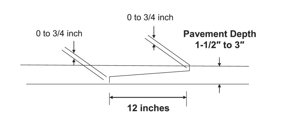
Figure 23-1: Notched Wedge Joint Detail
Refer to the Construction Divisions technical advisory report on Use of Tapered Longitudinal Joints such as the Notched Wedge Joint for additional information.