23.3.5 Temporary Geometry Requirements
The geometric alignment of the TCP should be similar to the geometric alignment of permanent design. Section 6B.01 of the
states: “The basic safety principles governing the design of permanent roadways and roadsides should also govern the design of TCP zones. The goal should be to route road users through such zones using roadway geometrics, roadside features, and TCP devices as nearly as possible comparable to those for normal highway situations.”
23.3.5.1 Horizontal Geometry
Horizontal geometrics for short duration, short term stationary, and intermediate term stationary traffic control alignments may be implemented using the diagrams in the
and
. These implementations are not likely to involve the temporary detour pavement, pavement markings, or concrete barriers that are often required for long term stationary alignments.
For long term stationary alignments, lateral shifts in the traffic not more than one lane width in distance may be designed using shift tapers. However, for traffic shifts greater than one lane width, or for complex alignment, designed horizontal curvature is preferable.
TCP horizontal curves should be designed so that the side forces on the vehicles do not exceed the recommended maximum safe side forces for various design speeds (refer to the Maximum f column of Table 3-7 of the 2018
).
The TCP design may require a shift of alignment of traffic in locations other than straight, normally-crowned roadway. The designer should consider the cross slope of the pavement upon which the curves are designed, and whether or not the cross slope is towards or against the direction of the curvature. Minimum radii for combinations of TCP design speed and cross slope are shown in
below.
TCP Design Speed | |||||||||
Cross Slope | f max 20% | f max 18% | f max 16% | f max 15% | f max 14% | f max 13% | f max 12% | f max 11% | f max 10% |
30 mph R (ft) | 35 mph R (ft) | 40 mph R (ft) | 45 mph R (ft) | 50 mph R (ft) | 55 mph R (ft) | 60 mph R (ft) | 65 mph R (ft) | 70 mph R (ft) | |
-8% | 500 | 817 | 1,334 | 1,929 | 2,778 | 4,034 | 6,000 | 9,389 | 16,334 |
-7% | 462 | 743 | 1,186 | 1,688 | 2,381 | 3,362 | 4,800 | 7,042 | 10,889 |
-6% | 429 | 681 | 1,067 | 1,500 | 2,084 | 2,881 | 4,000 | 5,634 | 8,167 |
-5% | 400 | 629 | 970 | 1,350 | 1,852 | 2,521 | 3,429 | 4,695 | 6,534 |
-4% | 375 | 584 | 889 | 1,228 | 1,667 | 2,241 | 3,000 | 4,024 | 5,445 |
-3% | 353 | 545 | 821 | 1,125 | 1,516 | 2,017 | 2,667 | 3,521 | 4,667 |
-2% | 334 | 511 | 762 | 1,039 | 1,389 | 1,834 | 2,400 | 3,130 | 4,084 |
-1% | 316 | 481 | 712 | 965 | 1,283 | 1,681 | 2,182 | 2,817 | 3,630 |
0% | 300 | 454 | 667 | 900 | 1,191 | 1,552 | 2,000 | 2,561 | 3,267 |
1% | 286 | 430 | 628 | 844 | 1,112 | 1,441 | 1,847 | 2,348 | 2,970 |
2% | 273 | 409 | 593 | 795 | 1,042 | 1,345 | 1,715 | 2,167 | 2,723 |
3% | 261 | 389 | 562 | 750 | 981 | 1,261 | 1,600 | 2012 | 2,513 |
4% | 250 | 372 | 534 | 711 | 926 | 1,187 | 1,500 | 1,878 | 2,334 |
5% | 240 | 356 | 508 | 675 | 878 | 1,121 | 1,412 | 1,761 | 2,178 |
6% | 231 | 341 | 485 | 643 | 834 | 1,062 | 1,334 | 1,657 | 2,042 |
7% | 223 | 327 | 464 | 614 | 794 | 1,009 | 1,264 | 1,565 | 1,922 |
8% | 215 | 315 | 445 | 587 | 758 | 961 | 1,200 | 1,483 | 1,815 |
Note that these TCP radii match the radii found in Table 3-13 Minimum Radii and Superelevation for Low-Speed Streets in Urban Areas,
, which follows Superelevation Distribution Method 2. However, this table has been developed to include higher TCP design speeds across a higher range of existing cross slopes using the formula V2/15R = e + f. The designer also has the option of using a more conservative superelevation methodology (see
).
should not be used for permanent design of high-speed facilities. Permanent conditions must use the superelevation methodology indicated in
).
23.3.5.2 Design Examples:
23.3.5.2.1 Example 1:
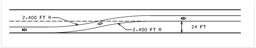
The TCP designer needs to lay out a long-term shift of traffic across a 2% normal crown where the work zone design speed is 60 mph and the traffic is being shifted laterally by 24-ft. A shift taper based on WS/2 would require 720-ft with a 1.9 degree diverging angle, while a reverse curve using a 2,400-ft radius could be accomplished in 479-ft. In this case the added complexity of laying out a reverse curve in construction may be justified in order to save nearly 250-ft of transition distance as well as resulting in smoother navigation of vehicles through the lateral shift.
 |
23.3.5.2.2 Example 2:
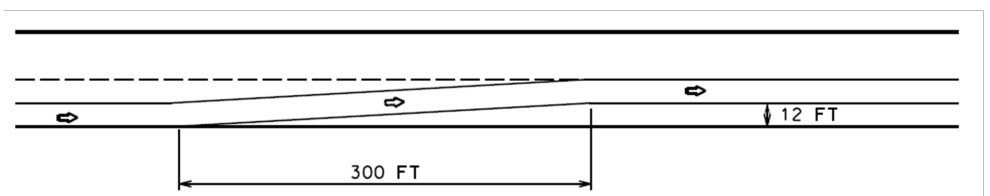
A TCP designer needs to lay out a long-term shift of traffic across a 2% normal crown where the work zone design speed is 50 mph and the traffic is being shifted laterally by 12-ft. A shift taper based on WS/2 should be adequate in this case resulting in a diverging angle of 2.3 degrees and a shift length of 300-ft, through which a vehicle may naturally spiral within the width of the lane as it navigates. Although a reverse curve using a 1,389-ft radius may be smoother and produce a slightly shorter shift length of 258-ft, the distance saved is probably not worth the additional complexity required for construction layout.
 |
23.3.5.2.3 Example 3:
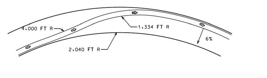
The TCP designer needs to lay out a long-term shift of traffic on existing or new pavement through a horizontal curve with a 6% superelevation where the work zone design speed is 60 mph. In this case the vehicle path could be curved opposite the direction of the the cross slope with a radius of 4,000-ft without exceeding the maximum side force. A tangent should be avoided as this might cause the driver to speed up. The vehicle path could be brought back into the horizontal curve with a 1,334-ft radius in the direction of superelevation slope. This would accomplish the shift in the minimum possible distance.
 |
23.3.5.3 Vertical Geometry
The K values of sag and crest vertical curves in a TCP design should use the same requirements as permanent design as specified in
. If these K values cannot be reasonably achieved, the designer should consider a further reduction in the work zone speed limit for the specific construction phase or location involved to shorten the stopping sight distance. This reduced speed should be clearly posted as an advisory sign.