19.6 Intersections and Crossings
Designing multimodal intersections requires intersection geometry that increases safety for all users in combination with effective and efficient traffic control measures. Changes in geometry can help to reduce vehicle turning speeds, facilitate safe crossings, increase pedestrian and bicyclist comfort and safety, and create space for dedicated bicycle facilities. One of the key considerations of intersection geometry is the location of pedestrian crossing ramps and crossings relative to vehicle paths. It should be noted that these principles apply to all roadways including frontage roads.
19.6.1 Pedestrian Crossings Principles
19.6.1.1 Speed of Vehicles
Many pedestrian-vehicle collisions occur at intersections. A key strategy to avoiding these crashes is reducing vehicle speeds, which should be complemented by other strategies, including providing adequate sight distance through sight triangles, providing a variety of signalization strategies at locations with signals, eliminating free-flowing movements (or using truck aprons in slip lanes to slow turning cars while accommodating the larger vehicles), and using infrastructure strategies that increase visibility such as curb extensions and parking restrictions near pedestrian crossings.
Wider curb radii can enable drivers to maintain higher speeds when turning, thus decreasing reaction time for potential conflicts with crossing pedestrians. Designing to minimum radii accommodates vehicle operating characteristics while providing some control over vehicle speeds.
Traffic volume and vehicle type influence the width and curvature of intersection corner radii. See
for Minimum Intersection Turning Radii.
19.6.1.2 Visibility
It is critical that pedestrians and drivers have clear sight lines to one another at crossings, both at intersections and mid-block crossings. This adequate sight distance allows vehicles to stop for crossing pedestrians. Higher speeds require longer sight distances. Design elements such as fences, plantings, buildings, and walls may obscure sight lines. Parked vehicles close to crossing locations can also obscure sight lines for both parties. When possible, these elements should be restricted or moved to another location to provide proper visibility. Several treatments discussed below can also improve visibility.
19.6.1.3 Frequency of Crossing Opportunities
In areas with high pedestrian volumes and denser land uses, pedestrian crossing opportunities should be closely spaced. “Crossing opportunities” are defined here as intersections or crossings that are equipped with appropriate control, signage, lighting, geometry, and markings that allow pedestrians to safely and comfortably cross the street. In the absence of frequent crossing opportunities, pedestrians will choose the most direct path of travel, thus creating opportunities for collisions with vehicles where pedestrians are unexpected, less visible, and more exposed. In general, the frequency of crossing opportunities should be at least as dense as the surrounding street grid. Where large gaps between crossings are identified, midblock crossing may be appropriate.
19.6.1.4 Crossing Distance and Alignment
Reducing street width improves pedestrian safety and comfort by shortening crossing times, reducing exposure to vehicle-pedestrian conflicts, and reducing vehicle delay. Pedestrian crossing distances should be minimized to the greatest extent reasonable. Shorter crossing distances may be achieved through any or a combination of the following treatments:
- Providing median refuge islands;
- Providing curb extensions;
- Realigning of crosswalks at offset or diagonal intersections;
- Reducing vehicle and parking lane widths; and
- Reducing the number of vehicle lanes.
Alignment of crossings is an important aspect to the safe crossing of streets for pedestrians. It is natural for pedestrians to cross the road at convenient locations; therefore, providing crosswalks in those locations that align to minimize distance and time crossing the road is important to consider.
19.6.1.5 Crossings at Intersections
Intersections should be designed to enable pedestrians to cross all legs. There may be limited circumstances where pedestrian access across a leg of an intersection may be prohibited, however, this should rarely be done unless there is a compelling reason to limit this movement. Pedestrians should not be directed to cross multiple legs of an intersection to access a corner that could otherwise be accessed by crossing a single leg. Crossing additional legs creates more exposure to vehicular traffic for pedestrians and forces pedestrians to travel longer distances.
19.6.1.6 Pedestrian Delay
Minimizing pedestrian delay when crossing the street increases a pedestrian’s convenience and reduces the likelihood that pedestrians will cross the street in an unsafe manner. At signalized intersections, pedestrian delay can be minimized by maintaining short signal cycles. At uncontrolled crossings, designers should provide pedestrians as much frequency and length of gaps in traffic as possible
19.6.2 Intersection Crossing Treatment Decision-Making Framework
There are many factors that can affect roadway crossing opportunities for pedestrians, including motorist approach speeds and volumes, motorist stopping and yielding behavior, roadway configuration, types of vehicles, the volume and assertiveness of crossing pedestrians, the amount of sight distance that can be achieved at the crossing location, and other factors. These factors will also vary based on time of day or day of the week, seasonally, or due to special events.
Pedestrian crash risk increases as traffic volumes and operating speeds increase and motorist stopping and yielding decreases. To mitigate locations with increased crash risk, countermeasures which increase motorists stopping and yielding, increase gaps, or reduce pedestrian exposure should be considered to facilitate the pedestrian crossing.
The
identifies a range of potential countermeasures which have been shown to achieve improved pedestrian safety at uncontrolled crossings.
includes an extensive matrix and list of countermeasures which have been found to be effective for improving pedestrian safety at uncontrolled crossing relative to specific combinations of roadway geometry and traffic operating conditions. This table provides an initial set of countermeasures options to consider. Not all countermeasures listed within the cell may be necessary to achieve the desired safety goals, however, there are often crossings where the application of multiple countermeasures can be beneficial such as the provision of a marked crosswalks, RRFB, and a crossing island to improve crossing opportunities at multi-lane roadways operating at moderate speeds. On lower speed, lower volume roadways, the application of a marked crosswalk with a complementary pedestrian crossing warning sign may be sufficient where existing night-time lighting levels are adequate.
can be used in conjunction with
to evaluate the potential for a countermeasure to address common safety issues.
Other resources which should be consulted to review potential countermeasures not included in these figures or within this guide which may be effective include:
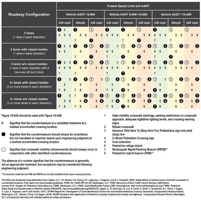
Figure 19-24A: Pedestrian Safety Countermeasures Based on Roadway Configuration and Posted Speed Limits and Annual Average Daily Traffic.
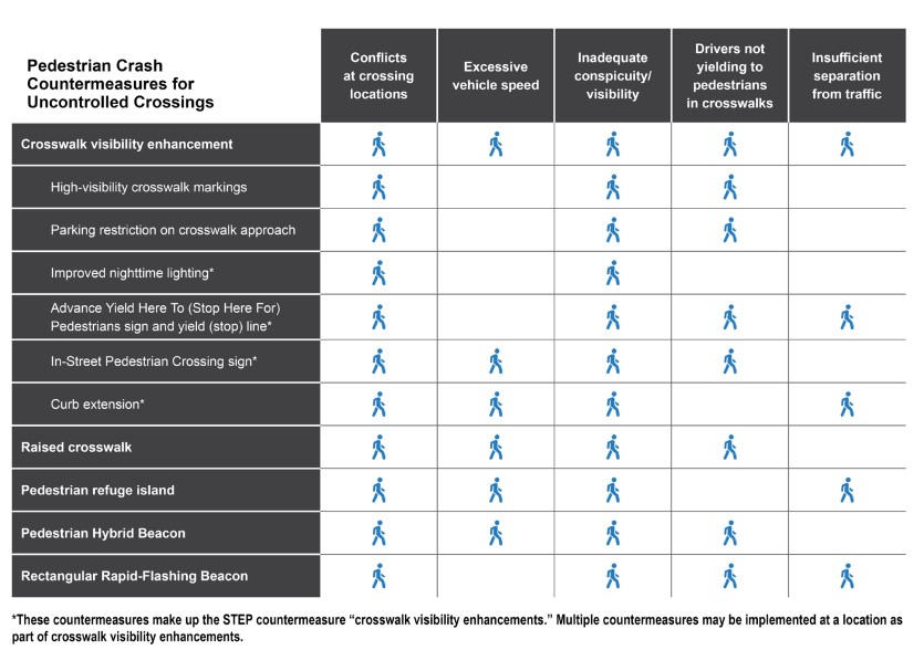
Figure 19-24B: Countermeasure Effectiveness for Common Safety Issues
19.6.3 Geometric Treatments for Pedestrians at Intersections
19.6.3.1 Medians and Refuge Islands
Raised medians have been proven to provide safety benefits to pedestrians when compared to flush (at street grade) medians and are therefore preferred as a safety measure at pedestrian crossings. Medians are generally used to divide traffic streams, such as in
where the midblock median separates two-way traffic and enables the pedestrian to cross one direction of traffic at a time. Channelization islands between turning lanes and through lanes can also act as refuge islands. A two-way center turn lane is not a raised median as it cannot provide safe refuge for crossing pedestrians.
19.6.3.1.1 Application
To improve pedestrian safety, refuge islands should be considered where street crossing distances are four travel lanes or greater. See
in
for further detail on application with respect to traffic volumes and speeds. Medians and refuge islands also reduce the speed of left turning movements at intersections which can also improve pedestrian safety where they are exposed to left-turning traffic.
Though they provide refuge, median islands should not be used to allow for traffic signal phasing that breaks the pedestrian trip into two phases. Pedestrians should be staged in the median at signalized intersections only on boulevard sections with wide medians that would add excessive pedestrian clearance interval. Where pedestrians are staged in the median, additional pedestrian signal heads and pushbuttons must be installed in the median. For locations with RRFB or pedestrian hybrid beacon (PHB), refuge islands may be used to create two-stage crossings.
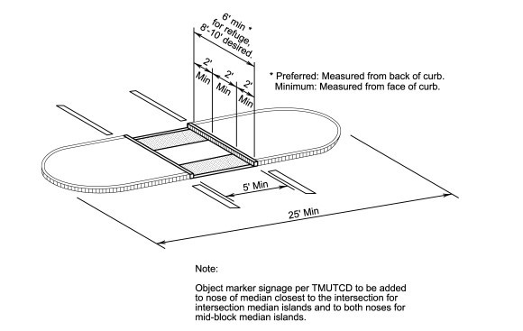
Figure 19-25: A Median Refuge Island.
19.6.3.1.2 Design Parameters
Median Width:
To function as a refuge (i.e., a place where pedestrians may stop to await a gap in traffic or a signal indication before completing their crossing), a raised median with a pedestrian access route cut through the island at a level flush with the roadway surface must be at least 6-ft wide, exclusive of the width of the curbs. An 8-ft or 10-ft median island width is desirable to provide additional clearance for wheelchairs and bicycles and to better accommodate groups of pedestrians. Length: At midblock locations, the minimum length of the median refuge is 25-ft. Advance lane tapers may be required to warn approaching motorists of the physical median following the guidance of the
and
.Accessibility:
See
.Crosswalk:
It is recommended that the cut-through for a median refuge be the full width of the crosswalk in the direction of pedestrian travel. The minimum width of a cut-through for a median refuge is 5-ft. Crossings through a median can be angled so pedestrians can see and be more aware of traffic on the roadway they are about to cross.At an intersection crossing, a “nose,” or curbed edge, that extends past the crosswalk toward the intersection is recommended to separate people waiting on the crossing island from motorists, and to slow turning motorists. The recommended minimum nose length is 2-ft.
19.6.3.1.3 Considerations
Medians and refuge islands can provide additional space for warning signs or beacons at multi-lane pedestrian crossings, increasing their visibility to approaching drivers.
19.6.3.1.4 Offset Crossing (“Z-style”) Median Islands
At uncontrolled locations (intersection or midblock), designers may consider a Z-style PAR configuration within the median island. This configuration reorients the pedestrian to face oncoming traffic, creating staggered crosswalks on either side of the island. Islands should be at least 12-ft wide to accommodate an accessible route in both directions and maintain maneuverability and passing distance for pedestrians using mobility devices. When used along a shared use path alignment, the design should also consider maneuverability for bicyclists, including bicycles with trailers or long wheel cargo bikes. This treatment is most appropriate in rural and suburban areas.
19.6.3.2 Curb Extensions/Bulb-Outs
Curb extensions are created by extending the sidewalk or curb line into the street at an intersection or mid-block crossing location in order to shorten the crossing distance for pedestrians and improve visibility at crossing locations.
19.6.3.2.1 Application
Curb extensions are recommended on streets that have on-street parking and can be used selectively in locations with shoulders where shortened pedestrian crossings are desired. Curb extension installation on both sides of a crossing is preferred, but where curb extension installation on one side is infeasible or inappropriate (i.e., no parking lane or shoulder), this should not preclude installation on the opposite side.
19.6.3.2.2 Design Parameters Width:
The width of parking lane minus 1-ft of offset to the travel lane.
Length
: The minimum length of a curb extension must be the width of the crosswalk although it can extend farther to match a no parking limit approaching the intersection. The length of a curb extension can also vary depending on the intended use (e.g., stormwater management, transit loading, restrict parking, bike parking) and potential for sight line improvement.19.6.3.2.3 Considerations
In proximity to transit stops, curb extensions can present challenges with bus maneuverability where they must pull to the edge of the roadway in advance of, or after, the curb extension. In these locations, the curb extension should be designed to enable buses to easily navigate to the edge of the roadway or consideration should be given to allowing the bus to stop in the travel lane by incorporating the curb extension into the bus stop, creating a bus bulb.
The radii of the curb extension should be designed so that street-sweeping equipment can reach the entire curb face without leaving gaps where debris can collect. Designers should consult with local jurisdictions regarding the operating characteristics of their sweeping equipment. Landscaping within a curb extension should be limited to low-level plants that will not impact sight distance.
shows an example of landscaping within a curb extension.
Curb extensions retrofitted onto a street can significantly alter drainage patterns. Drainage must be evaluated as part of the design of both full reconstruction and retrofit curb extensions.
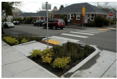
Figure 19-26: A Curb Extension with Landscaping.
19.6.3.3 Truck Aprons
A truck apron (
) is a design strategy used to accommodate the turning needs of large vehicles while slowing the turning speeds of smaller vehicles by reducing the perceived actual radius. A truck apron is designed to be mountable by larger vehicles to accommodate their larger effective turning radius needs. The mountable surface encourages the most common vehicles, a passenger (P) or delivery vehicle (SU), to turn outside the apron at a slower speed by design, thereby decreasing their effective turning radius.
19.6.3.3.1 Application
Truck aprons are applicable where slower vehicle turning speeds are a priority. They may be used at corners of standard intersections, as part of a channelization island, or as part of the central island of a roundabout. Truck aprons may be used at corners and islands that have either controlled or stop and yield condition vehicle movements. Truck aprons can be installed with corner reconstruction, or in a retrofit condition. When they are installed as a retrofit, or when a gap is left between the mountable curb and the curb face to facilitate surface drainage, they are called truck pillows.
19.6.3.3.2 Design Parameters
Color
: The apron’s color should be easily distinguishable in contrast with the surrounding roadway and sidewalk.Height
: A truck apron/pillow should incorporate a mountable section with a height between 2-in and 3-in to provide the desired traffic calming.Accessibility
: The accessible route across the truck apron should be clear and obvious to pedestrians with slopes and grades that meet the design requirements for a crosswalk. The pavement texture and surface slopes at this location should be smooth and meet accessibility standards. While texture is appropriate in other mountable portions of the apron, where the accessible route cuts through, the texture should be discontinued for the portion of the accessible route. Crosswalks should be marked up to the detectable warning surface through the truck apron to clearly distinguish the intended path of travel and have it to be recognized as part of the street. The detectable warning must be located behind the truck apron at the sidewalk.19.6.3.3.3 Considerations
The presence of a higher volume pedestrian or shared use path crossing should be considered as a condition for truck apron installation, especially in an area where drivers may be starting to accelerate, such as a freeway onramp.
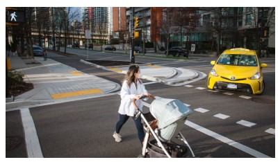
Figure 19-27: A Truck Apron.
19.6.3.4 Raised Crosswalks and Intersections
Sight lines between crossing pedestrians and drivers are essential for safety as are slower motorist approach speeds where they must stop and yield to crossing pedestrians. Placing pedestrians at a higher elevation through the intersection can make them more visible and slow the speeds of approaching motorists. This is especially important at locations where greater numbers of children or people using mobility devices may be present as they are lower to the roadway and can be more difficult to see and may have reduced ability to judge or react to approaching motorists.
19.6.3.4.1 Raised Crosswalk
Raised crosswalks continue the elevation of the sidewalk across a crosswalk in order to provide better visibility of and for pedestrians and to slow vehicle speeds in a manner similar to other vertical speed control elements.
19.6.3.4.2 Application
Raised crosswalks are possibly applicable in urbanized areas on streets with speeds of 35mph or less. They are also applicable at roundabouts and channelized right-turn lanes between the curb and a triangular island where drivers may have a stop or yield condition.
19.6.3.4.3 Design Parameters
Height:
The crosswalk should be raised approximately 3-in from the elevation of the roadway.Width
: The table of the crosswalk should be at least 10-ft wide, allowing both front and rear wheels of a typical passenger vehicle to be on top of the table at the same time.Approach ramp length
- The recommended length of the ramp up to the raised crosswalk is 8-ft.Markings
- Crosswalk markings are recommended for the top of the raised crosswalk.Accessibility
- The junction between the sidewalk and raised crosswalk should meet all applicable accessibility standards for crosswalks and curb ramps.19.6.3.4.4 Considerations
When designing a raised crosswalk, several other elements should be considered. These include:
- Drainage design will differ based upon whether the elevation of the crosswalk extends to the curb or not;
- Chevron-style markings may be used on the half of the ramp facing traffic for increased driver awareness of change in slope; and
- Consult with local emergency services providers regarding placement and design.
19.6.3.4.5 Raised Intersections
Raised intersections are those where the elevation of the entire center of the intersection is raised. Similar to speed humps and other vertical speed control elements, they reinforce slow speeds and encourage motorists to stop and yield to pedestrians at the crosswalk, while improving visibility for pedestrians and drivers. Crosswalks are typically placed on top of the raised area.
19.6.3.4.6 Application
Raised intersections are applicable in urban areas and towns with higher volumes of pedestrians, at minor intersections, on streets with speeds of 35 mph or less. They may be used at controlled or uncontrolled locations.
19.6.3.4.7 Design Parameters
Accessibility
- The junction between the sidewalk and raised crosswalk should meet all applicable accessibility standards for crosswalks and curb ramps.Drainage
- The presence of raised pavement can significantly alter the drainage characteristics of a street. Drainage must be evaluated as part of the design of raised crosswalks and intersections.19.6.3.4.8 Considerations
Raised intersections may have different pavement material to bring attention to the intersection. Ensure that materials within crosswalks meet ADA surface requirements.
19.6.3.5 Lower Speed Limits
Motor vehicle speed is known to contribute to crash severity and likelihood of survival for bicyclists and pedestrians. Speed is also a known factor that influences motorist stopping and yielding rates. Lowering the posted speed of roadways can result in the lowering of the operating speeds and improve pedestrian safety and improve motorist compliance with pedestrian safety countermeasures. Refer to TxDOT’s
for additional information on posted speed determination
19.6.3.6 Hardened Centerlines
Hardened centerlines are painted centerlines supplemented with vertical barriers at signalized or unsignalized intersections. Hardened centerlines change the path of travel through the intersection, creating tighter left turn radii which improves the visibility of pedestrians in the crosswalk and also reduces turning speed.
19.6.3.6.1 Application
Hardened centerlines are applicable in retrofit situations where the intersection has not been otherwise designed to slow turning vehicles and appropriately align them to provide drivers clear sightlines of crossing pedestrians.
19.6.3.6.2 Design Parameters
Hardened centerlines should implement the following design parameters:
Materials
: Materials for hardened centerlines should be sturdy, stable materials, such as plastic bollards and turning wedges. Refer to
for more information. Materials must be listed on the Material Producer List. Install products in accordance with manufacturer's specifications.Accessibility
: Hardened centerlines must not impede pedestrian crossings. Include cut-outs to provide a clear path of travel.19.6.3.6.3 Considerations
The use of hardened centerlines should decrease over time as intersections are built to principles with pedestrian safety in mind or are wholly retrofit with more permanent materials.
19.6.4 Uncontrolled Crossing Safety Countermeasures
Uncontrolled crossing locations are those where sidewalks or designated walkways intersect a roadway at a location where no traffic control (i.e., traffic signal or STOP sign) is present. These may be at intersection or midblock locations.
19.6.4.1 Marked Crosswalks with Uncontrolled Traffic Movements
As discussed in
, motorists must stop and yield the ROW to crossing pedestrians who are lawfully within a marked or unmarked crosswalk at intersections or at marked crosswalks at midblock locations. Marked crosswalks visually communicate to both pedestrians and drivers that pedestrian crossings are expected at that location and remind motorists of their responsibility to stop and yield to pedestrians.
19.6.4.1.1 Application
Marked crosswalks indicate optimal or preferred locations for pedestrians to cross and remind motorists to stop and yield the ROW to crossing pedestrians. They may be installed at any intersection location where it is desired to support pedestrian crossings.
In general, marked crosswalks and other safety treatments should be prioritized at locations where pedestrians desire to cross the street and are vulnerable to conflicts with vehicles such as locations with:
- High pedestrian and vehicular volumes;
- Locations where pedestrians are routinely expected typical of urban areas, rural town centers, school zones, parks, university or other similar pedestrian intense institutional land uses, or at bus stops;
- Locations with vulnerable populations such as children, senior citizens, people with disabilities, or hospital areas;
- Locations where traffic or geometric conditions make it difficult for pedestrians to cross creating safety challenges for pedestrians; and
- Locations with shared use path or trail crossings.
Marked crosswalk research shows that they are an effective treatment to increase motorist awareness of pedestrians and to improve understanding of ROW compared to unmarked crosswalks. However, this research also shows that marked crosswalks used alone may increase pedestrian crash risk if not used with other supplemental engineering treatments at uncontrolled crossings where the speed limit exceeds 40 mph and either:
- The roadway has four or more lanes of travel without a raised median or pedestrian refuge island and an ADT of 12,000 vehicles per day or greater; or
- The roadway has four or more lanes of travel with a raised median or pedestrian refuge island and an ADT of 15,000 vehicles per day or greater.
At these locations, it will be necessary to install other measures to reduce traffic speeds, shorten crossing distances, enhance driver awareness of the crossing, and/or provide active warning of pedestrian presence to supplement the marked crosswalk following the guidance in
.
A marked crosswalk is required to legally establish the midblock crossing per
.
19.6.4.1.2 Design Parameters
Marked crosswalks must follow
and further guidance found in
Section 3B.18.
shows an example of a typical marked crossing
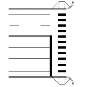
Figure 19-28: A Marked Crosswalk (Controlled Crossing)
19.6.4.1.3 Considerations
Supportive Traffic Control Signs
- Regulatory and warning traffic signs (see
) may be used at and in advance of a crosswalk where pedestrians may be unexpected, and it is desired to improve visibility of the crossing.Standard markings will incur wheel wear and need to be maintained over time. Longitudinal crosswalk markings should not be in the wheel path of vehicles. Center the crosswalk lines on travel lanes, lane lines, and shoulder lines (if present) to reduce wear, and thus reduce the need for maintenance. To provide better visibility on concrete roadways, the white crosswalk markings may be outlined with black contrast markings.
19.6.4.2 Stop Bars and Yield Lines
Stop bars (a.k.a. stop lines), yield lines, or advance yield markings improve safety at uncontrolled crossings on multilane roadways by improving visibility and decreasing the possibility of a multiple threat collision. These lines reinforce a driver’s responsibility to stop and yield to pedestrians in a crosswalk at an uncontrolled location or stop and yield condition movement within a signalized intersection, (e.g., a channelized right turn lane). Stop bars or yield lines are those placed in advance of a marked crosswalk. Refer to
Section 3B.16 and Figure 3B-17.
provides an example of a marked crosswalk at an uncontrolled intersection.
19.6.4.2.1 Application
See
and
for application. Because they are effective at mitigating multiple threat crashes, they should be considered at all marked, unsignalized crossings of multi-lane roadways. They may be used on single lane approaches to marked crosswalks where engineering judgment determines a need.
19.6.4.2.2 Design Parameters
Refer to Section 3B.16 of the
and the current
for further design guidance.
19.6.4.2.3 Considerations
Parking should be restricted on both sides of the street between the stop bars and yield line markings and the marked crosswalk to improve visibility. Refer to Section 3B.16 of the
for further guidance.
Stop bars may be staggered across lanes if appropriate.
“PED XING,” “SCHOOL XING,” or “TRAIL XING” pavement markings may be placed in advance of the stop bar pavement markings to identify the purpose of the stop bars is a crossing along with a corresponding warning sign.
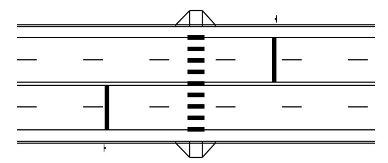
Figure 19-29: Stop Bars at a Marked Crosswalk (Uncontrolled Crossing)
19.6.4.3 Supportive Signs
The functions of signs are to provide regulations, warnings, and guidance information for road users. They can be supplemented with markings. Any information intended for pedestrians must be accessible to all pedestrians. The following discussion focuses on the most common signs needed to support engineering treatments in this chapter. The
describes the use and application of other signs not discussed which may be beneficial to accommodating pedestrians.
Wayfinding is discussed in
below
19.6.4.4 Pedestrian Crossing Warning Sign Assemblies
19.6.4.4.1 Application
Pedestrian traffic warning signs should be used at and in advance of a marked or unmarked crosswalk to notify motorists of the crossing and improve visibility of the crossing as a baseline treatment to marked crosswalks. See
and
for application. The message should reflect the type of crossing (pedestrian (W11-2), school (S1-1), and trail (W11-15 or W11-15a)). See
.They should be used at all marked, uncontrolled crosswalks. Refer to
Section 2C.50 for guidance and standards for use. School zone traffic control is further covered in Chapter 7 of the
.

Figure 19-30: Pedestrian Crossing Warning Signs (left to right): Pedestrian Crossing, School Crossing, Pedestrian and Bike Trail Crossing, and Trail Crossing.
19.6.4.4.2 Considerations
Signs may be mounted back-to-back on the same sign post to allow double posting of signs on the left and right side of the road to improve visibility to approaching motorists. Signs should be such that visibility is not obscured by other signs, utility poles, buildings, or vegetation.
An advanced placement of these signs should be considered in locations where sight distance is obstructed, or the crossing may be unexpected following the guidance of
Section 2C.05.
Beacons or flashers can be used to supplement warning signs and can be mounted Table of Contents Instructions Reference Links Roadway Design Manual | 19-54 on the sign post with the warning sign or over the crossing. They can flash continuously or be actuated by a pedestrian waiting to cross; however, these signs have been shown to be more effective if actuated. Actuation can occur when a pedestrian uses a pushbutton or through passive detection such as infrared. Wherever pedestrian actuated systems are installed, they should be accessible.
19.6.4.5 Pedestrian Crossing Regulatory Sign Assemblies
19.6.4.5.1 Application
The “Stop Here for Pedestrians” series signs (R1-5b, R1-5c, R1-6a, and R1-9a) may be used to notify approaching motorists of their responsibility to stop and yield to crossing pedestrians at uncontrolled crossings. See
and
for application. Refer to Section 2B.11, 2B.12, and Section 3B.16 of the
for further standards and guidance.
shows the current signs at the date this manual was published.
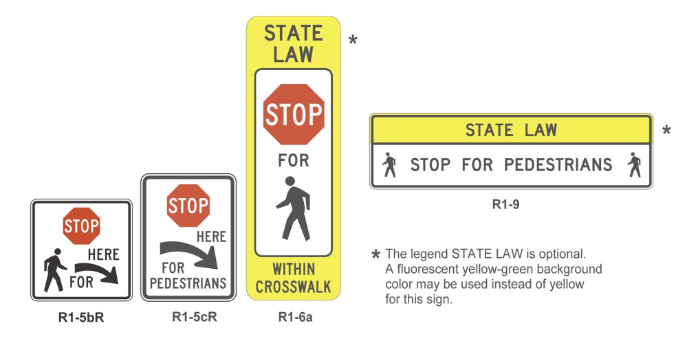
Figure 19-31: Unsignalized Pedestrian Crossing Signs.
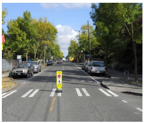
Figure 19-32: Pedestrian Stop Sign at an Uncontrolled Intersection.
19.6.4.5.2 Considerations
In-street Stop for pedestrian sign (R1-6a) have been found to be effective at increasing motorist stopping rates on roadways operating at 30 mph or less with ADT of 25,000 or less (see
).
19.6.4.6 Rectangular Rapid Flashing Beacon
A Rectangular Rapid Flashing Beacon (RRFB) is a device that supplements a warning sign that consists of amber LEDs that use an irregular flash pattern to draw roadway users’ attention to a crossing when a pedestrian is present. They may supplement any of the warning signs discussed in
. RRFBs are generally actuated with a pedestrian push button but may also be activated through passive detection. The pedestrian push button or passive detection device shall activate a speech message that indicates the status of the beacon (e.g., “Flashing lights are on”). If the pedestrian push button is used, it shall not include vibrotactile features as this feature communicates that walk indication is provided for a pedestrian signal.
As of September 11, 2018, RRFBs have interim approval for use across Texas though they do not appear in the current (2011) edition of the
. Contact the TRF for specific guidance on the use of RRFBs. As of the publishing of this manual, the link for interim approval of RRFBs can be found in the
19.6.4.6.1 Application
RRFBs can be used at and in advance of an uncontrolled marked or unmarked crosswalk to notify motorists of the crossing and improve visibility of the crossing as a baseline treatment at locations where static signs or flashing beacons are not sufficient to induce motorist stopping and yielding. See
and
in
for application.
19.6.4.6.2 Considerations
On multi-lane roadways, consider the visibility of roadway edge signs to drivers in the middle lanes. Where a median island is present, placement of additional RRFB assemblies there may increase visibility and thus stopping and yielding compliance. RRFBs may also be placed in advance of the crossing on higher speed roadways or at locations with sight distance restrictions providing motorists sufficient time to react to the device to slow and stop and yield to crossing pedestrians. The advance sign(s) can be designed to wirelessly communicate when the crossing is actuated. The R1-5b signs and advanced stop bar markings may also be used with the RRFB. Care should be taken such that R1-5b signs do not restrict motorists’ view of the flashing beacon at the crosswalk.
shows an example of an RRFB.
Solar-powered assemblies can eliminate the need for connecting to a power source.
Figure 19-33: Rectangular Rapid Flashing Beacon.
19.6.5 Signalized Crossing Safety Countermeasures
19.6.5.1 Warrants
Warrants specified in Chapter 4C of the
govern the installation of traffic signals at intersections, including provisions to accommodate pedestrians. Engineering studies to support the evaluation of traffic signal warrants must include a review of pedestrian characteristics and volume and whether the location is a school crossing.
19.6.5.2 Standard Signals
19.6.5.2.1 Application
Traffic signals provide benefits to pedestrians by stopping automobile traffic and allowing a designated phase for pedestrians to cross a roadway. See
and TxDOT’s
for further guidance on the use of traffic signals.
19.6.5.2.2 Consideration
The needs of all pedestrians should be taken into account when designing traffic signals at intersections where they can be expected to cross. Pedestrian safety, comfort, and convenience at intersections is fundamentally impacted by several major design decisions including cycle length, crossing time, and phase selection. Signalized intersections should be designed for pedestrians to cross in one phase. Wait times for pedestrians at traffic signals should be minimized. Substantial delays encourage pedestrians to violate the traffic signals and cross against Don’t Walk signals. Phasing based on other factors (volume, anticipated turning volumes, etc.) should be reviewed for its adequacy in accommodating pedestrian travel across each intersection leg. Long cycle lengths which dramatically increase pedestrian delay during periods of lower traffic volumes can reduce pedestrian compliance rates inducing attempts to cross during gaps in traffic. This is a particular concern during evening hours when pedestrian fatalities are highest.
19.6.5.3 Pedestrian Hybrid Beacon
A Pedestrian Hybrid Beacon (PHB) is a pedestrian-activated warning device located on the roadside, or on mast arms over midblock or intersection pedestrian crossings. The beacon head consists of two red lenses above a single yellow lens. The beacon head is dark until the pedestrian wanting to cross the roadway presses the button and activates the beacons.
This device provides an additional tool for improving the safety of crosswalks when traffic signals do not meet warrants. PHBs should be used in conjunction with signs and pavement markings to warn and control traffic at locations where pedestrians enter or cross a street or highway.
Districts must receive TRF Division approval for installation of a PHB for each location.
As of the publishing of this manual, the link for interim approval of RRFBs can be found in the
and
.
19.6.5.3.1 Application
See
and
and refer to
for application. PHBs are generally more applicable on wider, higher volume roadways where a stop and yield condition does not provide reliable, safe, and frequent opportunities for pedestrians to cross.
All of the following conditions must be met for a PHB to be considered:
- An engineering study must be performed and meet the guidelines detailed in Chapter 4F of the ;
- An established crosswalk with adequate visibility, markings and signs;
- A posted speed limit of 40 mph or less (does not include school speed zones);
- 20 pedestrians or more crossing in one hour;
- Location deemed as a high-risk area (e.g., schools and shopping centers); and
- Crosswalk is more than 300 ft. from an existing, traffic controlled pedestrian crossing.
Refer to Chapter 4F of the
for specific design standards and guidelines.
19.6.5.3.2 Considerations
Designers may justify a PHB in a location that currently has low pedestrian traffic (less than 20 pedestrians per hour) if:
- It can be demonstrated the PHB will attract more pedestrians once installed; or
- Nearby land use changes are expected to generate higher pedestrian volumes.
shows an example of a PHB.
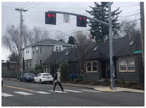
Figure 19-34: A Pedestrian Hybrid Beacon.
19.6.5.4 Use of Pedestrian Signal Faces
19.6.5.4.1 Application
Pedestrian signal faces aid in crossing by communicating timing and permission specific to pedestrian travel who may be crossing at a traffic signal or a Pedestrian Hybrid Beacon.
Pedestrian signal heads should be provided at all signalized crossings with sidewalks and curb ramps on the approaches, as well as at all signalized crossings where pedestrian activity is expected, regardless of the presence of sidewalks. Refer to Chapter 4E of the
for guidance and standards, including for accessible pedestrian signals (APS).
19.6.5.4.2 Considerations
Marked crosswalks should be installed at all crossings with pedestrian signals. See
for details.
Pedestrian signal faces may be timed and phased differently from the general traffic signal face, thus better accommodating the differing travel characteristics and speeds of pedestrians. Refer to Section 4E.03 of the
for further specifications regarding the application of pedestrian signal faces.
19.6.5.5 Actuation
Pedestrian actuation may impact signal or beacon operation in two ways: 1) actuating pedestrian beacons or signal heads that direct pedestrians’ crossing behavior, and/or 2) it may also change overall operations of a signal to extend a pedestrian phase only when pedestrians are present, thus allowing them to cross the full width of an intersection leg in one phase.
19.6.5.5.1 Accessible Pedestrian Pushbuttons
APS allow pedestrians to actuate a signal or beacon by pressing a button. APS also provide audible and vibrotactile indications, tactile arrow information communicating the orientation of the crosswalk, and a locator tone to assist pedestrians in finding the pushbutton. APS are required at all signalized intersections with pedestrian signal faces. Some emerging technologies allow pedestrians to activate the signal by waving a hand in the vicinity of the button as well, but this functionality is in addition to the required APS features noted above. Refer to
Sections 4E.08 through 4E.13 for guidance and standards regarding use of pushbuttons.
19.6.5.5.2 Application
APS push buttons are required at all signals and pedestrian hybrid beacons that include pedestrian signal heads they are also required at RRFBs. See
for push button location area.
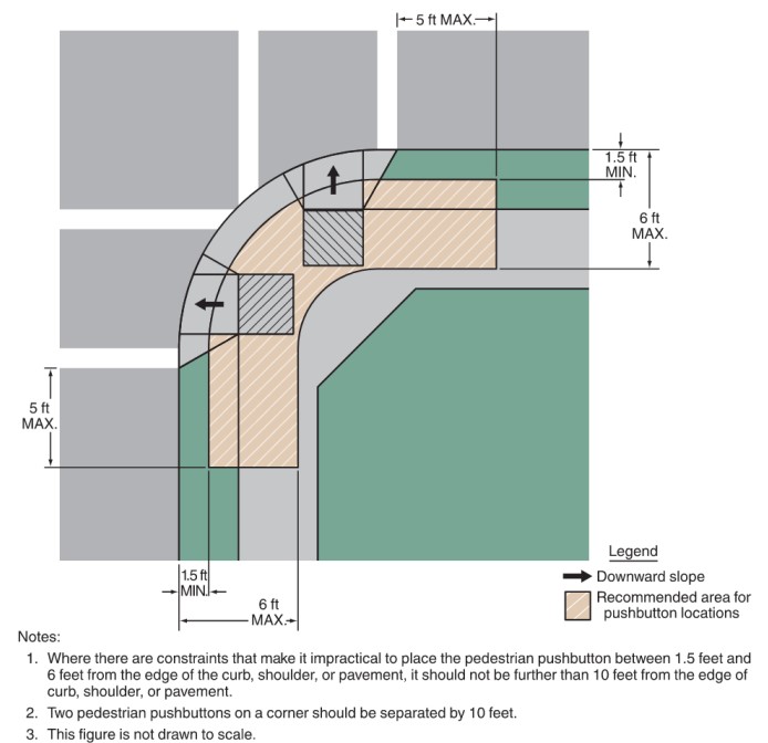
Figure 19-35: Preferred Pushbutton Location Area
Source: 2011 TMUTCD
19.6.5.5.3 Considerations
If the button is mounted on its own pole, the pole should not obstruct the pedestrian access route. The pushbutton must always be accessible from the pedestrian access route with a maximum side reach of 10-inches.
Though it is not desirable to design for an intersection where pedestrians are most likely Table of Contents Instructions Reference Links Roadway Design Manual | 19-60 to cross in two stages (curb to median, median to curb), where signal design necessitates this operation, a pushbutton must be provided in the median refuge for pedestrians to activate the pedestrian signal heads for the second crossing.
At signals and pedestrian hybrid beacons, the use of audible or visual confirmation of detection at signals communicates to pedestrians that the WALKING PERSON indication is forthcoming can improve signal compliance and is required by
. At RRFBs, there is no confirmation message because the flashing lights are activated each time the button is pressed.
Signal supports may be excluded from clear zone requirements. See
and
for further considerations when placing signal supports within the clear zone.
19.6.5.5.4 Passive Detection
Passive detection systems consist of one of several types of technologies (e.g., infrared, microwave, etc.) to detect pedestrians’ presence near the point of departure at a crosswalk.
19.6.5.5.5 Application
Passive detection may be used to activate pedestrian phases and signal heads and may be used to adjust pedestrian clearance time when a pedestrian is detected. Passive detection does not replace the need for APS pushbuttons as the pushbuttons are still needed to communicate audible and vibrotactile information.
19.6.5.6 Timing Considerations
Signal timing may be designed or amended to create a safer, more comfortable pedestrian environment through several strategies. Signalized intersections are common locations for pedestrian-vehicle collisions, most often with turning vehicles. Collisions can occur between parties traveling the same direction (right-turn conflict) or in opposing directions (left-turn conflict). Collisions may also occur between pedestrians and vehicles traveling in perpendicular directions when pedestrians do not have adequate crossing time and remain in the roadway once the signal changes, or when either party fails to obey traffic controls. The strategies below can aid in avoiding these conflicts.
19.6.5.6.1 Protected Turn Phasing
Signal phasing that includes protected left-, right- or both turn phases can benefit pedestrian safety by removing potential conflict through separating pedestrian and vehicle travel in time. Pedestrians crossing an intersection leg proceed with the through movement in the same direction while turning traffic is held.
19.6.5.6.2 Application
Protected phasing should be considered where pedestrian volumes are anticipated to be high, where there are high percentages of child or older pedestrians, and at locations with multiple conflict point turn lanes across a crosswalk. Protected phasing should also be considered where intersection geometry allows vehicles to turn in excess of 20 mph while executing turning movements. The pedestrian crossing interval must meet the requirements of Section 4E.06 of the
.
19.6.5.6.3 Considerations
Application of protected turn phasing to an existing signal should be accompanied by the installation of an accessible pedestrian signal so pedestrians with disabilities will follow the same behavior as other pedestrians. Intersections with right and left turn lanes and pedestrian crossing islands create the opportunity to create exclusive pedestrian phases by restricting motorists turning movements to shared right and left turn overlaps. The exclusive pedestrian crossing can be provided concurrent with through moving motorists.
During periods of lower traffic volume protected phases could be adjusted to permissive with flashing yellow arrows for right and/or left turns across pedestrian crossings. This can provide flexibility to reduce conflicts during the pedestrian walk phase at key times during the day or during special events limiting times of protected phases to periods with the greatest need.
19.6.5.6.4 Leading Pedestrian Intervals
A Leading Pedestrian Interval (LPI) activates the white WALK indication for the crosswalk while a red indication continues to be displayed for vehicle traffic (through and/or turning) in the same direction. This allows pedestrians to proceed into the crosswalk in advance of vehicle movements, thus making them more visible to turning drivers who may cross their path of travel. They are a proven FHWA Safety Countermeasure. Refer to Section 4E.06 of the
for further guidance.
19.6.5.6.5 Application
An LPI should be considered for locations with high pedestrian volumes and high volumes of turning vehicles or locations with a history of crashes between pedestrians and turning motorists.
19.6.5.6.6 Design Parameter
If a leading pedestrian interval is used, they should be timed to allow pedestrians to cross at least one lane of traffic or, in the case of a large corner radius, to travel far enough for pedestrians to establish their position ahead of the turning traffic before the turning traffic is released. A typical LPI interval range is between 3 and 7 seconds with a minimum of 3 seconds. There is no maximum interval, however long intervals may be better served by completely protected crossing phases.
19.6.5.6.7 Considerations
Application of an LPI to an existing signal should be accompanied by the installation of an accessible pedestrian signal so pedestrians with disabilities will follow the same behavior as other pedestrians.
If a leading pedestrian interval is used, consideration should be given to prohibiting turns across the crosswalk during the leading pedestrian interval. See
for additional information.
19.6.5.7 Supportive Signs
19.6.5.7.1 Crosswalk Restrictions
Intersections should be designed to enable pedestrians to cross all legs. There may be limited circumstances where pedestrian access across a leg of an intersection may be prohibited, however this should rarely be done unless there is a compelling reason to limit this movement. Pedestrians should not be directed to cross multiple legs of an intersection to access a corner that could otherwise be accessed by crossing a single leg. Crossing additional legs creates more exposure to vehicular traffic for pedestrians, forces pedestrians to travel longer distances, and increases travel time. If pedestrian crossings at unmarked crosswalks must be restricted, sign types R9-2, R9-3 (
), or other appropriate regulatory signs must be installed to face pedestrian approaches of restricted crosswalks. Also note that prohibited crossing locations shall not include curb ramps, and the pedestrian circulation path must be separated from the roadway with landscaping or other non-prepared surface or separated from the roadway by a detectable vertical edge treatment with a bottom edge 15-inches maximum above the pedestrian circulation path.
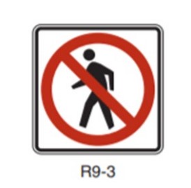
Figure 19-36: Restricted Pedestrian Crossing Sign.
19.6.5.7.2 Motorist RTOR Restrictions
Right Turn on Red (RTOR) introduces pedestrian safety concerns because drivers scanning for gaps in traffic on their left may not look for pedestrians on their right. Allowing drivers to turn right or left during a pedestrian WALK signal is a frequent cause of crashes between pedestrians and drivers and can impede a pedestrian’s ability to complete their crossing by delaying their entry into the roadway. At locations which allow RTOR, motorists are likely to encroach into the crosswalk while watching oncoming vehicles, further eroding pedestrian safety and comfort. These conflicts can be reduced by restricting RTOR movements. The
suggests that “prohibiting RTOR should be considered where exclusive pedestrian phases or high pedestrian volumes are present.”
Right turn-on red can be restricted when activated by a pedestrian push button by using NO RIGHT ON RED blank-out signs to limit the restriction to times when pedestrians are present.
19.6.5.7.3 Turning Traffic Stop and Yield
Left and right turning motorists at signals can account for a high percentage of conflicts and crashes with pedestrians at locations with permissive phasing. Where conflicts between turning motorists and crossing pedestrians are likely, a TURNING VEHICLES STOP FOR PEDESTRIANS (R10-15a) sign should be considered. This sign may be used for both left and right turning traffic.
19.6.6 Mid-block Pedestrian Crossing Safety Countermeasures
Midblock pedestrian crossings may be appropriate in a variety of contexts based on pedestrian desire lines, transit stop locations, land use context, and intersection spacing. Motorists are more likely to expect pedestrians at intersection locations and often are driving at higher speeds in midblock locations. Because of this, the use and design of midblock crossings should be deliberate to address pedestrian safety and improve motorist compliance.
Given the differences between intersection and midblock crossings, there are several key considerations designers must keep in mind:
- The crossing location should be convenient for pedestrians;
- Motorists should be alerted of the crossing as they approach it;
- Pedestrians must be able to assess opportunities to cross; and
- All users must be made aware of their responsibilities and obligations at the crossing and designers must provide opportunities to meet those responsibilities and obligations.
Designers should consider pedestrian volumes, motorist volumes, types of vehicles, traffic speeds, roadway characteristics (e.g., number of travel lanes), and adjacent land use context when determining if a midblock crosswalk should be provided. Additionally, pedestrians have a strong desire to stay on their path of travel and do not want to go unnecessarily out of their way to utilize a crossing, so crossing locations should be placed at or near the pedestrians’ desired path of travel.
19.6.6.1 Location Considerations
To promote and achieve high compliance, midblock crossings should be located where intersection spacing is excessive and there is a natural desire line for the pedestrians’ path of travel. These conditions may include some of the following:
- Signalized intersection spacing exceeds 600-ft;
- A shared use path intersects a street midblock;
- Transit stops are located midblock;
- Existing pedestrian demand demonstrates a need (e.g., parking lot and office building on opposite sides of the roadway); and
- New or existing development generates heavy pedestrian traffic (e.g., shopping center, school, etc.).
19.6.6.2 Crossing Treatments
The guidance in
through
for pedestrian crossing treatments and countermeasures is similarly applicable to midblock crossings. Refer to the latest
and the
for guidance on additional signing and markings for midblock crossings.
19.6.7 Pedestrian Facilities at Alternative Intersections
Pedestrian facilities should be included at alternative intersections using the same design principles that apply for standard intersections and midblock crossings. For alternative intersection treatments, adequate sight distance is particularly important as vehicles and pedestrians are often approaching one another at non-right angles. See
for further guidance on these intersections.
19.6.8 Pedestrian Treatments at Railroad Crossings
Texas has a network of railroad systems, which are operated and controlled by federal, local, and State laws and regulations. Where the rail networks cross pedestrian facilities, it is important to follow specified guidance that makes the crossing safe and predictable for the pedestrian and rail operator. All pedestrian facilities should be designed to minimize pedestrian crossing time, and devices should be designed to avoid trapping pedestrians between sets of tracks.
- Traffic Control. The has guidance on signage, gates, flashing beacons, and other rail crossing warning devices to communicate with pedestrians at railroad crossings. Traffic studies may be needed to determine the level and type of traffic control that should be used. Refer to the for more guidance.
- Passive and Active Devices. May be used to supplement highway-related active control devices to improve non-motorist safety at highway-rail crossings. These devices should be considered at crossings with high pedestrian traffic volumes, high train speeds or frequency, extremely wide crossings, complex highway-rail crossing geometry with complex ROW assignment, school zones, inadequate sight distance: and/or multiple tracks. Passive or Active Devices should always be used if no highway-related active control devices are present.
- Passive devices include fencing, swing gates, pedestrian barriers, detectable warning surfaces, pavement markings, texturing, refuge areas, and fixed message signs.
- Active devices include flashers, audible active control devices, automated pedestrian gates, pedestrian signals, variable message signs, and blank-out signs. Railroad operating practices may not support installation of pedestrian only devices.
- Refer to and report for further detail on these treatments.
- Visibility- Clear sightlines should be established so that pedestrians can clearly see oncoming trains and assess whether there is adequate time to cross.
- Approach Angle- Perpendicular crossings are preferred in order to provide adequate sight lines and decrease the risk of mobility device wheels getting stuck in flangeway gaps. Where the roadway crossing is skewed, consider widening or providing a bend out in the sidewalk at the rail crossing that allows for a crossing angle closer to perpendicular, preferably between 60 and 90 degrees.
- Flangeway Gaps- requires flangeway gaps have a maximum width of 3-in for tracks that are subject to safety regulations at 49 CFR part 213, issued by the Federal Railroad Administration (FRA), and 2.5-in for tracks not subject to FRA Safety Regulations.
- Detectable Warning Surfaces-Detectable warning surfaces (DWS) must be placed on either side of an at-grade crossing only when the crossing is not located in the street. The DWS must be placed a minimum of 6-ft and a maximum of 15-ft from the centerline of the nearest rail.
- The detectable warning must be, at minimum, 2-ft wide in the direction of pedestrian travel and shall extend the full width of the crossing.
- Where pedestrian gates are provided, detectable warning surfaces shall be located on the side of the gate opposite the rail. Pedestrian gates shall not overlap detectable warning surfaces.
- Quiet Zones- Note that specific standards apply to pedestrian crossing treatments and signage for designated quiet zones. Refer to the Federal Railroad Administration materials related to quiet zones for more information.
More details on design options and treatments can be found in the
Chapter 2 and report “
.”