13.9 Right Turn Slip Lanes
13.9.1 Urban Design
Right-turn slip lanes at urban intersections must be designed to accommodate both motorists and pedestrians. Considerations should be given for crosswalk compliance by motorists and pedestrians, design vehicle accommodations, speed of turning traffic, provisions of auxiliary lanes, adjacent land uses, visibility of anticipated pedestrian traffic, and acuity of the cross-street traffic from the right turn drivers’ perspective. In areas where pedestrian activity is moderate to high, raised crosswalks may be installed to slow turning motorists and improve their likelihood of stopping and yielding to crossing pedestrians. A raised crosswalk may in some instances have the benefit of reducing the length of a required ramp on the pedestrian island. However, raised crosswalks are not recommended along highspeed facilities. If the slip lane is a multilane crossing for pedestrians, one or more of the following must be provided: a traffic signal, pedestrian hybrid beacon, a rectangular rapid flashing beacon, and/or a raised crosswalk.
The following recommendations address these considerations and are reflected in the configurations shown in
(with a deceleration lane) and
(without a deceleration lane).
Angle of Entry -
The angle of entry between the slip lane and the cross street is recommended to be 70 degrees. This configuration slows motorists, reduces the head-turning movement to look for gaps in oncoming traffic, and makes it easier for motorists to identify crossing pedestrians. If an angle of 70 degrees is not achievable due to constraints, reduce it accordingly. The minimum recommended angle is 55 degrees.
Curb Radii and Curb-to-Curb (throat) Width -
Most traffic on urban streets is expected to be passenger cars and single-unit trucks. However, to accommodate the turning movement of larger vehicles, the curb radius, and curb-to-curb width can be designed for a larger design vehicle while striped to delineate the path for a smaller vehicle. For guidance on curb radii design for different vehicle classes, see
. See
below for lane markings.Channelizing Island -
Islands are recommended to have a minimum side length of 15-ft, excluding the corner radii, refer to
. Channelizing islands should be offset from the edge of the traveled way to reduce their vulnerability. A 12-ft side length may be used in special circumstances, where the 15-ft minimum cannot be met due to highly constrained conditions. See
for design guidance on curb offset and tapering. In the presence of a bicycle lane, which serves as a separation between the curb and the travel lane, curbs need not be offset. Additional information on appropriate curb type and design, see
and
.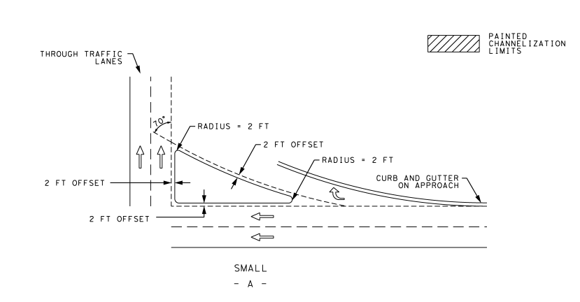
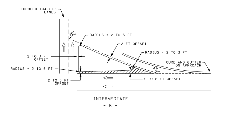
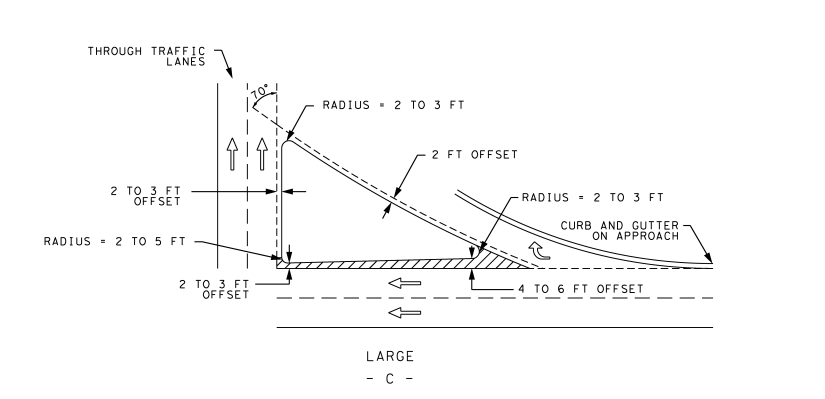
Figure 13-11: Details for Channelizing Island Design for Right-Turn Slip Lane
Pedestrian accommodations are a central component of the design. The pedestrian access routes across channelizing islands are sometimes set at the top of curb elevation using a series of curb ramps and landings (
).
Smaller channelizing islands may not have adequate space to provide the necessary curb ramps, so the pedestrian access route can be cut through the island flush with the gutter grades of the roadway (
).
This option is preferred
since it is easier for some pedestrians to navigate, especially those with vision disabilities and does provide some wayfinding benefits. However, it can also collect water and debris, increasing maintenance needs.A third option is to raise the accessible route to at least 2-in above the roadway gutter grade (
). This solution helps reduce the maintenance required for cut-through islands and still provides some wayfinding clues. If a raised crosswalk is used, this would also result in a reduction in the length of the needed ramp for the options depicted in
and
.
Provide flared sides where the pedestrian circulation path crosses the curb ramp as shown in
and
. Flared sides shall be sloped at 10 percent maximum, measured parallel to the curb. Curb returns may be used only where pedestrians would not normally walk across the ramp because the adjacent surface is planted, substantially obstructed, or otherwise protected.
All components of the accessible route should be constructed at a minimum 5-ft width to provide adequate room for pedestrian passage.
If partial cut-through sections are used, a 10 percent flare and rounded corners along the pedestrian pathway should be used to provide better wheelchair mobility.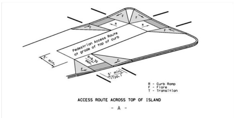
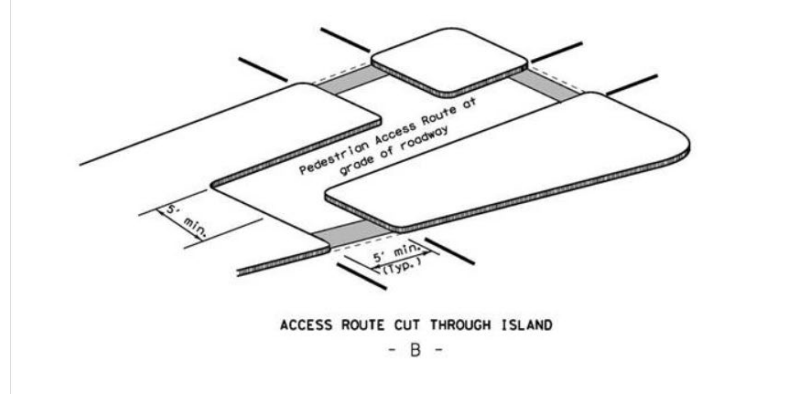
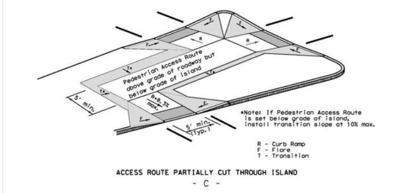
Figure 13-12: Combination Island Ramps (Per Pedestrian Facilities Curb Ramp Standards)
Deceleration Lane -
These lanes allow motorists to decrease speed before negotiating a turn while separated from through traffic. This separation helps pedestrians identify right-turning vehicles. Refer to Number, Location, and Spacing of Access Connections in Chapter 2 of the
for volume thresholds for installing deceleration lanes. See
for design recommendations for deceleration lanes.If conditions do not necessitate a deceleration lane or ROW is restricted, consideration should be given to using a taper, see
. See
and
for sample right-turn slip lane designs with and without a deceleration lane.
Acceleration Lane -
Acceleration lanes typically are not used on urban streets since:- They make it more difficult for pedestrians, especially the visually impaired, to cross the turning roadway;
- Cross-street drivers do not expect merging traffic; and
- Acceleration lanes and driveways create unneeded conflicting movements between the driveway and acceleration lane.
Accordingly, acceleration lanes are not advisable where pedestrian activity is anticipated.
Drainage -
Any necessary inlets should be designed and placed on the upstream side of the crosswalk at a location that prevents—or limits to the extent practical—the spread of water into the crosswalk. Cut-through access should be situated to minimize paths for water flow. Avoid placing drainage low points at or near the ADA curb ramps.Lighting -
Intersections with channelization should be illuminated. Lighting helps motorists identify islands, diverge and merge locations, turning roadways, and pedestrian crossings. Adequate lighting at urban intersections, including illumination of crossing locations, is important—particularly where pedestrian activity is expected at night. Refer to Chapter 6, of TxDOT’s
for pole placement guidelines.Apparatus and Pole Placement -
ITS equipment, signal, utility poles, and apparatuses should be outside of paved pedestrian walkways and landing areas. Refer to the
and TxDOT standard drawings for guidance on mounting heights and limits on object protrusion into pedestrian facilities. When pedestrian facilities are not initially installed, care should be taken to avoid the placement of apparatuses and poles in anticipated or planned locations of future pedestrian walkways and landing areas.Crosswalk Location -
Crosswalks should be placed toward the middle of the channelized island with a minimum of 20-ft between the crosswalk and yield line
for the intersecting street as shown in
and
. Crosswalks may be placed near the beginning of the channelized island if conditions do not permit a centralized location, or it is more conducive to the natural pathway of pedestrians. When the crossing is located at the beginning of the channelized island, care should be taken to place it such that there is enough space available at the ramp location for an appropriate landing area. Placement of the crosswalk near the end of the turning roadway is not recommended as motorists are expected to encroach on the crosswalk as they yield to oncoming traffic. Also, motorists arriving at the downstream end of the turning roadway typically focus their attention on cross-street traffic rather than crossing pedestrians.Crosswalk Orientation -
The pedestrian crosswalk should be oriented perpendicular to the turning roadway to shorten the crossing distance for pedestrians and to place approaching vehicles in the periphery of pedestrians.Crosswalk Markings -
At locations where pedestrian activity is anticipated, a “High-Visibility Longitudinal Crosswalk” pattern is recommended to delineate the crossing location. The transverse markings facilitate wayfinding for visually impaired pedestrians and the inclusion of longitudinal lines provides additional visibility for approaching motorists. Alternatively, longitudinal markings alone can be installed to define the crossing path. Refer to the
for further guidance on the installation of crosswalk markings.Signage and Pavement Markings -
Yield signs are typically the appropriate traffic control devices for right-turn slip lanes at urban intersections. The yield line is used alongside the yield sign to draw attention to the need to yield to cross-street traffic. Refer to the
and
for guidance on yield sign and yield line placement. Where there is high pedestrian activity or when driver compliance is in question, additional signing may be used (see
).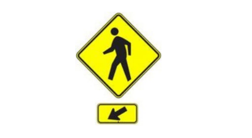
Figure 13-13: Supplemental Crosswalk Signs
Source: W11-2 and W16-7P Sign and Plaque (TMUTCD)
The travel lane should be striped to a minimum of 10-ft in width (11-ft typical) to accommodate a passenger vehicle, and the void area (shoulder) may be delineated by diagonal lines as shown in
and
. A raised truck apron may also be considered in the void area to further enhance the channelization of passenger vehicles.
Bicycle Lane -
When a bicycle lane is used, it should be striped appropriately to define ROW and shared spaces. Refer to Chapter 18, the
, as shown in the
, and as detailed on
for bicycle lanes. Bicyclists intending to make a right turn can use the right-turn lane/turning roadway and operate like a motorized vehicle.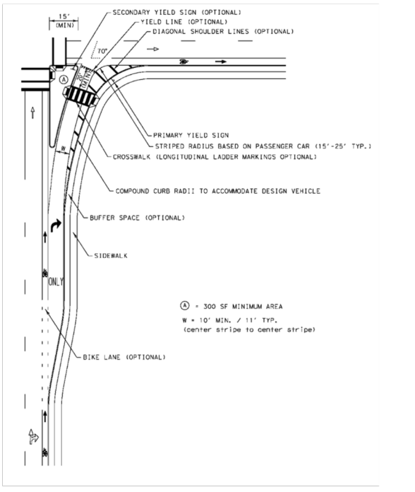
Figure 13-14: Right-Turn Slip Lane Design for Urban Intersections with Deceleration Lane
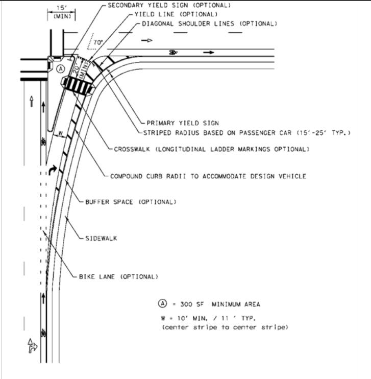
Figure 13-15: Right-Turn Slip Lane Design for Urban Intersections without Deceleration Lane
13.9.2 Suburban Design
Pedestrian activity on suburban roadways tends to be in the range of light to moderate. The following recommendations address the presence of pedestrians and facilitate potential future retrofits without heavily impacting mobility.
Angle of Entry -
See guidance provided under
.Curb Radii and Curb-to-Curb (Throat) Width -
The radii and throat width for right-turning roadways in suburban areas should be designed to accommodate larger vehicles. In the event that the area becomes more urbanized in the future, the turning roadway can be striped to delineate a tighter radius, promoting lower speeds and improving visibility of pedestrians for motorists (see
and
). See Cross Sectional Elements in
for striped lane width.Channelizing Island -
See guidance provided under
.Deceleration Lane -
See guidance provided under
.Acceleration Lane -
Acceleration lanes may be used; however, they make it more difficult for pedestrians, especially those with visual impairments, to cross the turning roadway. Therefore, acceleration lanes are not advisable where pedestrian activity is anticipated.Drainage -
See guidance provided under
. When pedestrian facilities are not initially installed, consideration should be given to determine where crosswalks may be installed in the future to avoid conflicts with inlet locations.Lighting -
See guidance provided under
.Apparatus and Pole Placement -
See guidance provided under
. When pedestrian facilities are not initially installed, care should be taken when placing ITS equipment, apparatuses, and signal and utility poles to avoid the anticipated or planned location of future pedestrian walkways and landing areas.Crosswalk Location -
See guidance provided under
. If an acceleration lane is present, consider placing the crosswalk at the upstream end of the turning roadway, placing pedestrians in the line of sight for drivers as they decelerate to make the turn. At the downstream end, on approach to an acceleration lane, drivers will be accelerating out of the turn and more likely focusing on cross-street traffic.Crosswalk Orientation -
See guidance provided under
.Crosswalk Markings -
See guidance provided under
.Signage -
See guidance provided under
. Bicycle Lane -
See guidance provided under
.13.9.3 Rural Design
If pedestrian activity is expected, see
.
If pedestrians are not an issue, the following guidelines may be used:
Angle of Entry -
In rural areas, the angle of entry between the slip lane and the cross street is typically flatter than in urban areas to facilitate high-speed turns.Radius -
For guidance on radius design for different vehicle classes, see
. A design speed that is appropriate for the turning movement should be used to determine the combination of radius and superelevation for the right turn.Channelizing Island -
The channelizing island may be flush with the pavement or depressed.Careful consideration should be made in rural areas for the use of curbed islands, particularly along high-speed facilities and at isolated intersections. If curbs are installed, they should be sloped and offset from the traveled way, and islands should be made clearly visible to motorists. Refer to Chapter 9 of
for design guidance on curb offset and tapering (
). For details on island approach treatment and delineation refer to Chapter 3 of the
and Chapter 9 of
.
Deceleration Lane –
Refer to Chapter 2 of TxDOT’s
for volume thresholds for installing deceleration lanes. See
in this manual for design guidance for deceleration lanes. Acceleration Lane –
Refer to Chapter 2 of TxDOT’s
for volume thresholds for installing acceleration lanes. These lanes provide a benefit when right-turn volumes are especially high and/or the speed differential between turning vehicles and vehicles on the cross street is large. Acceleration lanes provide benefits to motorists by allowing them to reach a higher speed prior to merging but they may increase sideswipe crashes. Acceleration lanes have been found to be preferred by elderly drivers at high-speed intersection locations. See
for design recommendations for acceleration lanes for two-lane and multi-lane rural highways, respectively. Lighting -
Intersections with channelization should be illuminated.