Section 4: Freeway-to-Freeway Interchange Signing
Single Exit Directional Interchange
Figure 5‑9 illustrates a directional interchange where all traffic exits the freeway at a single location. Signing for typical approaches to a single-exit directional interchange is illustrated in Figure 5‑10 through Figure 5‑13.
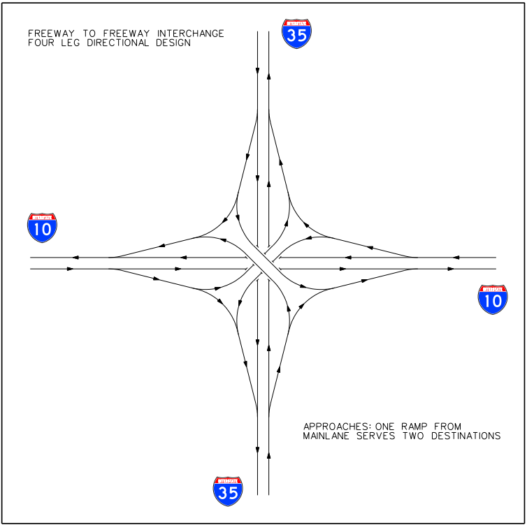
Figure 5-9. Four-leg directional interchange with one ramp from freeway main lanes serving two destinations.
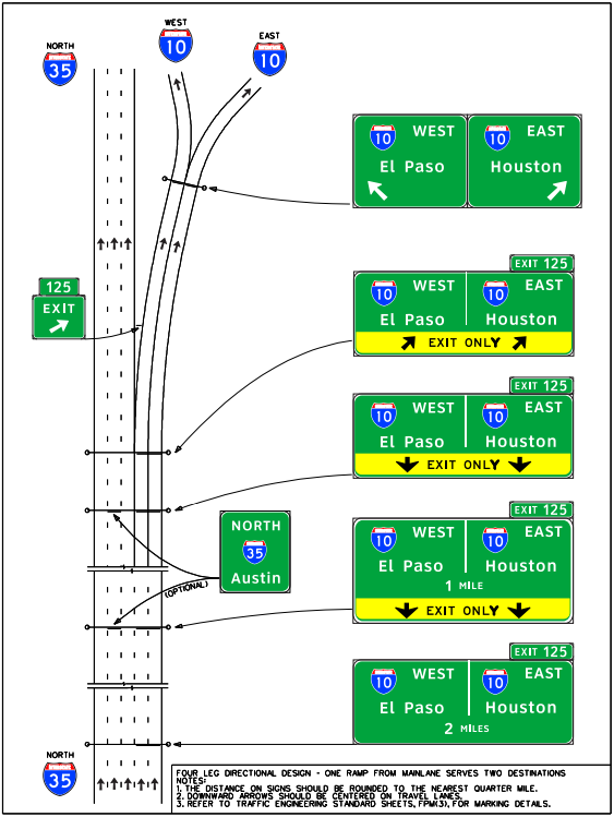
Figure 5-10. Signing for a four-leg directional interchange – one ramp from the freeway main lanes serves two destinations, double lane drop, and one-lane connectors to the left and right.
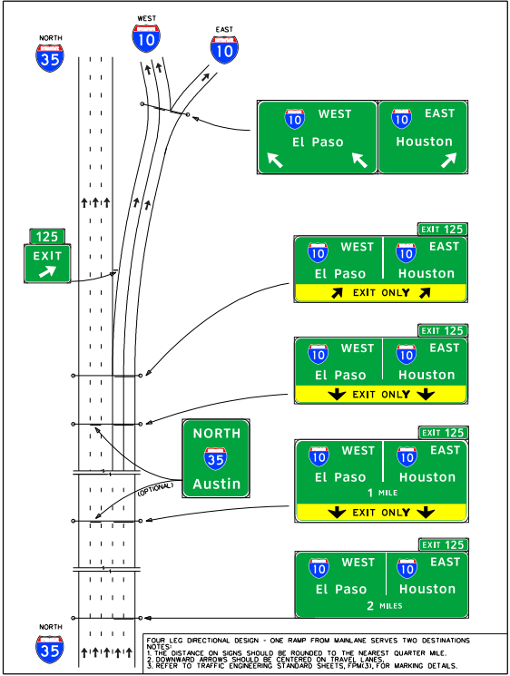
Figure 5-11. Signing for a four-leg directional interchange – one ramp from the freeway main lanes serves two destinations, double lane drop, two-lane connector to the left, and one-lane connector to the right.
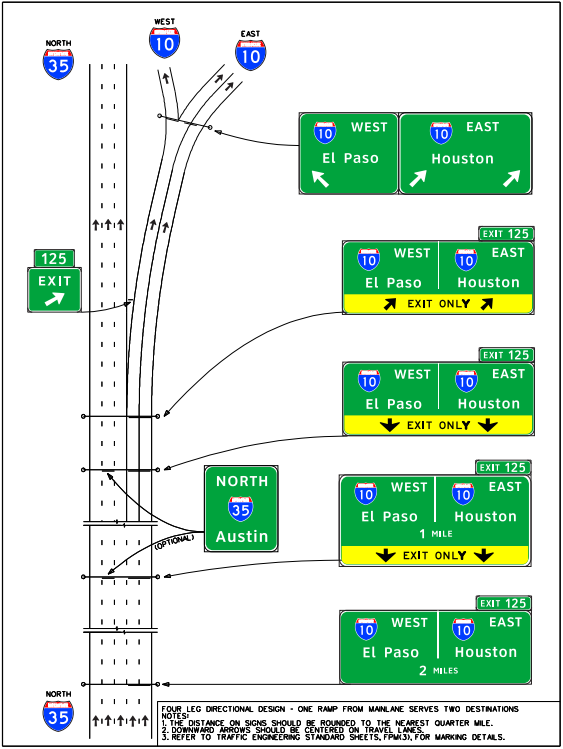
Figure 5-12. Signing for a four-leg directional interchange – one ramp from the freeway main lanes serves two destinations, double lane drop, one-lane connector to the left, and two-lane connector to the right.
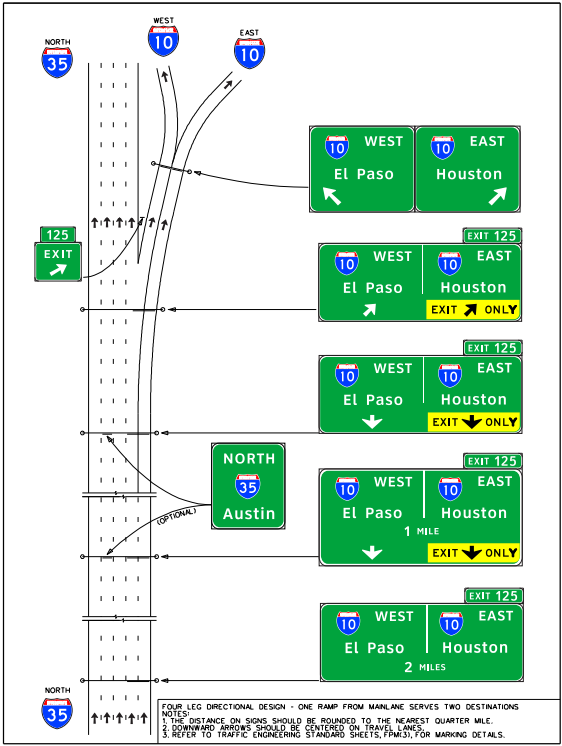
Figure 5-13. Signing for a four-leg directional interchange – one ramp from the freeway main lanes serves two destinations, single lane drop, optional exit, and one-lane connectors to the left and right.
Two Exit Directional Interchange
Figure 5‑14 illustrates a directional interchange where traffic exiting the freeway exits at two locations. Signing for typical approaches to a two-exit directional interchange is illustrated in Figure 5‑15 through Figure 5‑18.
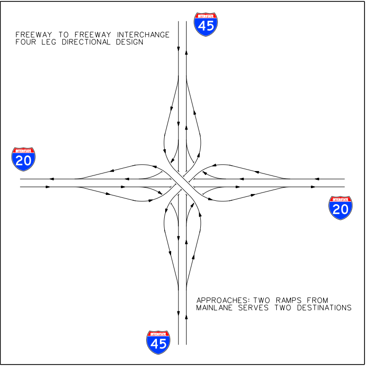
Figure 5-14. Four-leg directional interchange with two ramps from freeway main lanes serving two destinations.
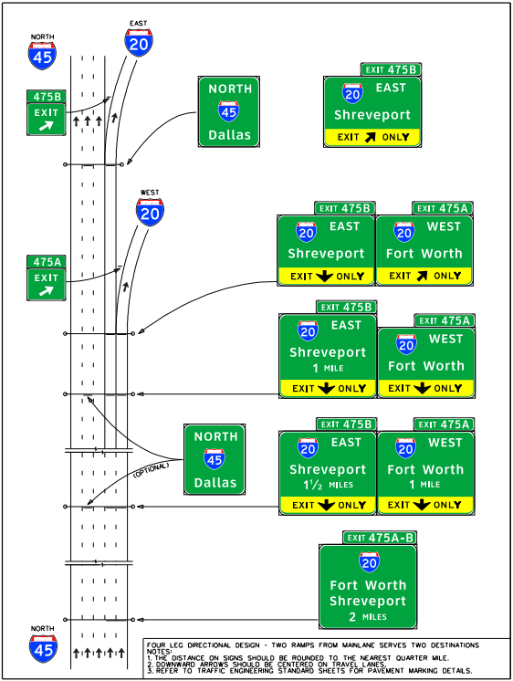
Figure 5-15. Signing for a four-leg directional interchange – two ramps from the freeway main lanes serve two destinations and lane drop for both ramps.
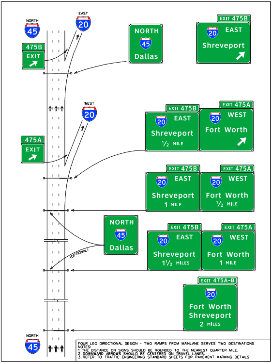
Figure 5-16. Signing for a four-leg directional interchange – two ramps from the freeway main lanes serve two destinations, single right-lane exit both ramps.
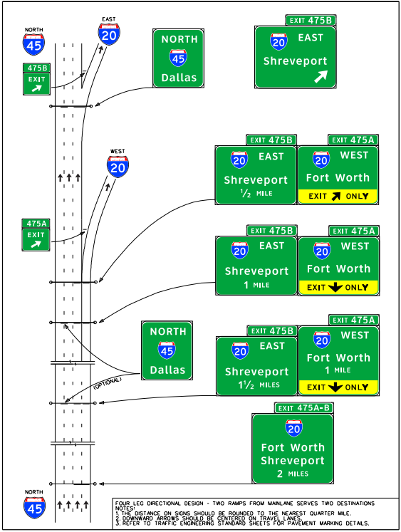
Figure 5-17. Signing for a four-leg directional interchange – two ramps from the freeway main lanes serve two destinations, single right-lane drop for first ramp, and single right-lane exit for second ramp.
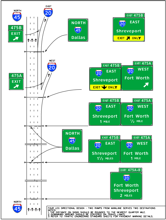
Figure 5-18. Signing for a four-leg directional interchange – two ramps from the freeway main lanes serve two destinations, single right-lane exit for first ramp, and single right-lane drop for second ramp.
Three-Leg Directional Interchange
Figure 5‑19 illustrates three-leg directional interchanges with various configurations of continuing and terminating routes. Figure 5‑20 through Figure5‑22 illustrate appropriate signing for the freeway approaching the split for each of the configurations.
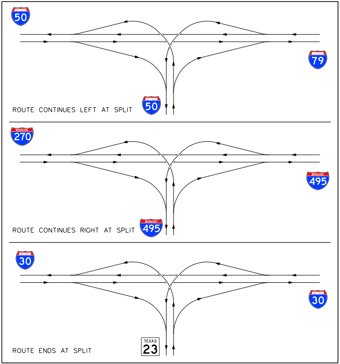
Figure 5-19. Three-leg directional interchanges with continuing and terminating routes.
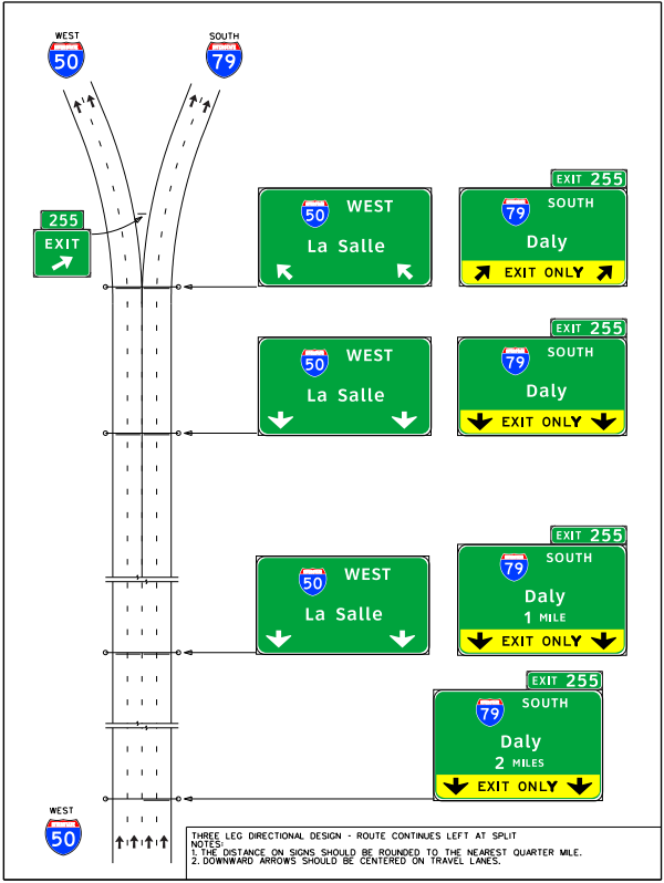
Figure 5-20. Signing for a three-leg directional interchange approach with route continuing left at the split.
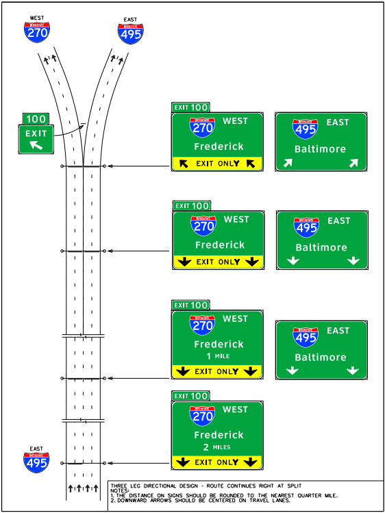
Figure 5-21. Signing for a three-leg directional interchange approach with route continuing right at the split.
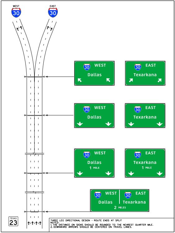
Figure 5-22. Signing for a three-leg directional interchange approach with route ending at the split.
Cloverleaf Interchange Designs
Figure 5‑23 illustrates a full cloverleaf interchange with collector-distributor roads and where all traffic exiting the freeway exits at one location. Signing for typical approaches to a cloverleaf interchange with and without collector-distributor roads is illustrated in Figure 5‑24 and Figure 5‑25.

Figure 5-23. Cloverleaf interchange with collector-distributor roads.
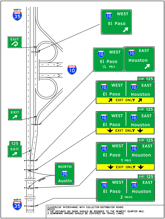
Figure 5-24. Signing for a typical cloverleaf interchange with collector-distributor roads.
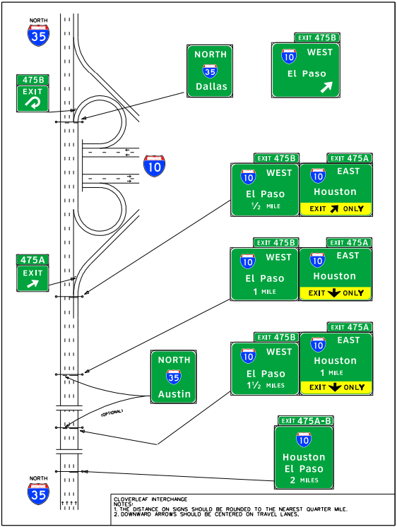
Figure 5-25. Signing for a typical cloverleaf interchange without collector-distributor roads.