Three-Leg Directional Interchange
Figure 5‑19 illustrates three-leg directional interchanges with various configurations of continuing and terminating routes. Figure 5‑20 through Figure5‑22 illustrate appropriate signing for the freeway approaching the split for each of the configurations.
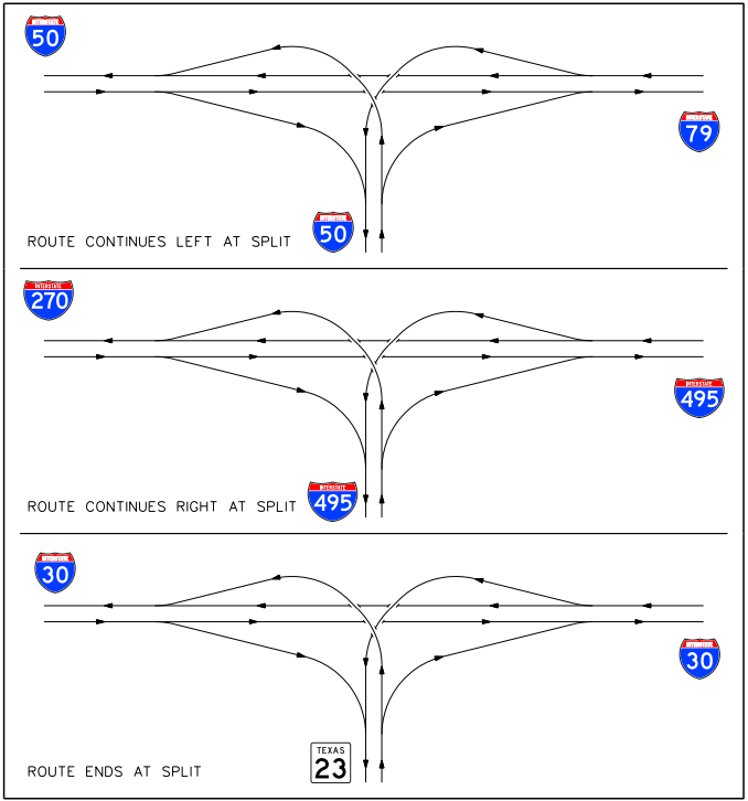
Figure 5-19. Three-leg directional interchanges with continuing and terminating routes.
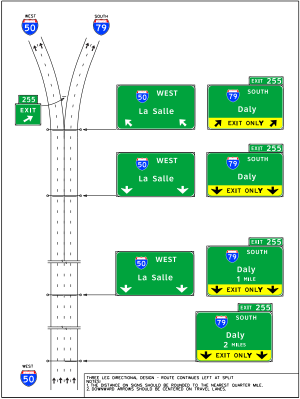
Figure 5-20. Signing for a three-leg directional interchange approach with route continuing left at the split.
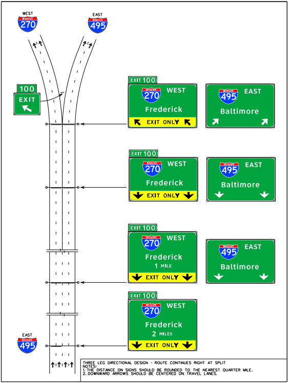
Figure 5-21. Signing for a three-leg directional interchange approach with route continuing right at the split.
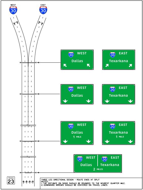
Figure 5-22. Signing for a three-leg directional interchange approach with route ending at the split.