17.6 Determining Length of Need of Barrier
The shape of the obstacle, its location with respect to travel lanes, the volume of traffic, its corresponding clear zone width, and the lateral location of barrier are the primary variables influencing length of barrier need. Barrier can be rigid, such as a concrete barrier, or semirigid, such as metal beam guard fence.
17.6.1 Variables
After all practical means to free the roadside of obstacles have been exhausted, certain areas may remain which constitute an obstacle to errant vehicles. These areas, as illustrated in
, will be referred to as an “area of concern.”
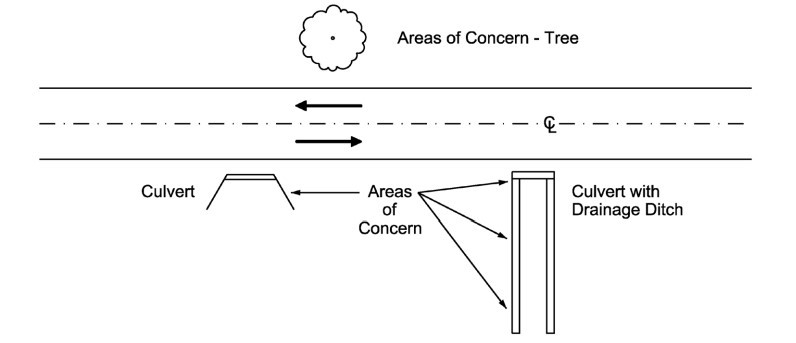
Figure 17-7: Areas of Concern
illustrates the variables of interest in the layout of approach barrier to shield an area of concern. The total length of need is equal to the sum of the following variables:
Equation 17-1
Where:
- Ltotal= Length of guard fence needed, ft
- Lu= Guard fence Length Upstream of area of concern, ft
- Lp= Guard fence Length Parallel to area of concern, ft
- Ld= Guard fence Length Downstream from area of concern, ft
When discussing length of need as it pertains to metal beam guard fence, L
u
is the length of guard fence needed to shield the area of concern for adjacent traffic. Upstream refers to the guard fence upstream of traffic adjacent to proposed guard fence. Ld
is the length of guard fence needed to shield the area of concern for opposing traffic. For roadways serving one-way traffic operations, Ld
= 0. Ld
is greater than zero for two-way operations when the area of concern lies within the clear zone of opposing (northbound in
) traffic as measured from the centerline pavement markings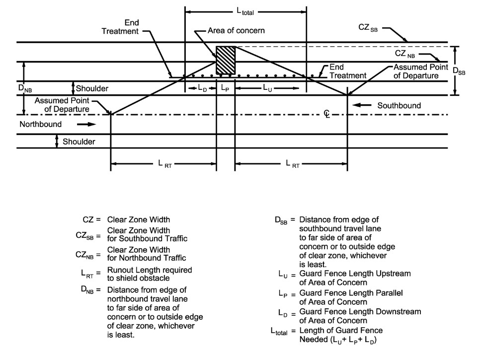
Figure 17-8: Variables Involved in Barrier Layout
In certain instances, judgment should be exercised to supplement design chart solutions and provide for additional safety. For example, high severity fixed objects (e.g., bridge columns) may justify minimum guard fence treatment when located outside the clear zone if geometric conditions (i.e., steep fill slope, outside of horizontal curvature, etc.) increase the likelihood of roadside encroachments. Also, bridge class culverts require protection inside and outside the clear zone. If a bridge class culvert is outside the clear zone, consider increasing the offset of the metal beam guard fence to decrease the length of need. Maintain a 4-ft minimum distance away from the obstacle and provide a maximum slope of 1V:10H or flatter for the placement of the metal beam guard fence. If the bridge class culvert is either inside or outside the clear zone, Du equals the clear zone distance. Additionally, Du equals the clear zone distance for any bridge structure.
17.6.2 Design Equations
To determine the needed length of guard fence or barrier required for a given obstacle, design equations have been formulated for low volume (ADT 750 or less) and higher volume (ADT more than 750) conditions. A clear zone width of 16-ft and length of roadside travel of 200-ft are incorporated in the low volume design equation (for use on roadways when the present ADT volume is 750 or less). Also, if the clear zone required is less than 16-ft and the present ADT is 750 or less, use
for calculating the guard fence length of need.
ADT ≤ 750 | Equation 17-2 |
Equation 17-3 | |
ADT > 750 | Equation 17-4 |
Equation 17-5 |
Where:
L
u
= Length of guard fence needed (upstream of area of concern), ftL
d
= Length of guard fence needed (downstream of area of concern), ftD
u
= Distance from edge of travel lane to far side of area of concern or to outside edge of clear zone, whichever is least, ft (for upstream direction of traffic)D
d
= Distance from edge of travel lane to far side of area of concern or to outside edge of clear zone, whichever is least, ft (for opposing direction of traffic)G
u
= Guard fence offset from edge of travel lane adjacent to proposed guard fence, ftG
d
= Guard fence offset from edge of opposing direction of travel lane (centerline), ftFor low volume conditions, if the clear zone width of 16-ft is met or exceeded, L=0.
For higher volumes, a clear zone width of 30-ft and length of roadside travel of 250-ft are incorporated into the design equation (for use on roadways when the present ADT volume is more than 750)
For high volume conditions, if the clear zone width (30-ft) is met or exceeded, L=0.
17.6.3 Using Design Equations to Determine Length of Guard Fence
Before determining length of guard fence, the designer should assemble the following pertinent data:
- Present ADT volume;
- Clear zone (horizontal clearance);
- Traffic operations (one-way or two-way);
- Lateral and longitudinal dimension of the area of concern;
- Shoulder width;
- Offset distance of the area of concern from the edge of travel lane (including from the centerline markings for two-way traffic operations);
- Approach grading, (i.e., will slopes be 1V:10H or flatter);
- Placement location, lateral offset measured to barrier face (alongside shoulder vs. near object, flared, etc.); and
- Presence of other nearby areas of concern which should be considered simultaneously
Once this design data has been assembled, the equation for length of guard fence can be used.
Where the prescribed length of the guard fence cannot be installed at a bridge end due to an intervening access point such as an intersecting roadway or driveway, the length of guard fence may be interrupted or reduced. This change in length is acceptable only in locations where the Department must meet the obligation to provide access and this access cannot be reasonably relocated. Alternative treatments in these situations include installing an appropriate radius rail, terminating the guard fence prior to the access location with an appropriate end treatment and continuing the guard fence beyond the access location if necessary, or using an alternate bridge end treatment. The selected treatment should consider potential sight line obstructions, crash history at the site, cost, and maintenance associated with the selected treatment. Reduced guard fence length to accommodate access points will not require a design exception or a design waiver.
provides example problems and solutions using the design equations.
The guard fence lengths produced by the equations should be rounded up to an even length of guard fence.
In circumstances where site conditions permit, the rounded-up length of need should terminate at the end of guard fence.
Any additional length of need component available from an end attenuator should be considered an additional buffer.
17.6.4 Example Problems
Example Problem 1
Given:
A rural two-lane collector highway containing 6-ft wide shoulders and a current ADT of 500 is illustrated in
. The area of concern is a 16-ft design clear zone that includes 1V:2H side slopes on a 10-ft high embankment section that is 125-ft in length alongside the highway.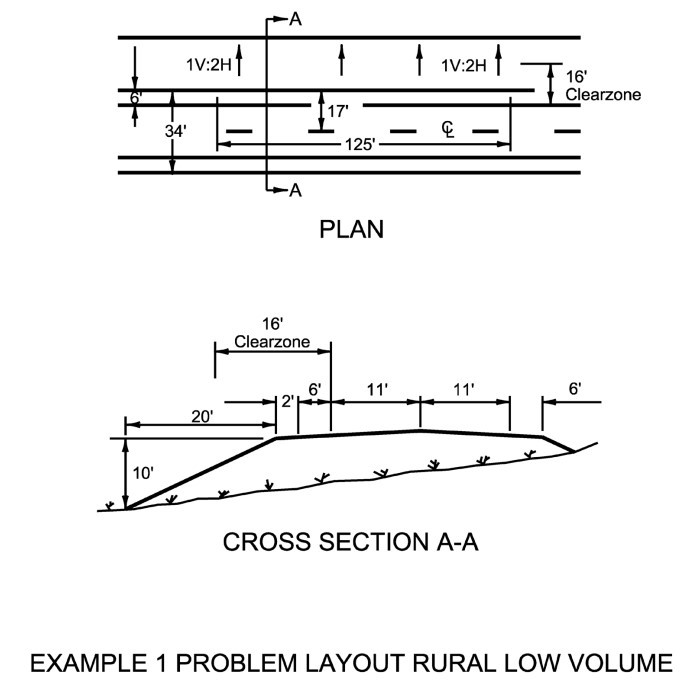
Figure 17-9: Example 1 Problem Layout Rural Low Volume.
Solution:
From the information above and referring to
it is determined that a “rail is needed.” As shown in
, the length of need is Ltotal
= Lu
+Lp
+Ld
. From the given information, Lp
= 125-ft. Because the ADT is less than 750,
and
are used to solve for Lu
and Ld
, respectively (if necessary).For the upstream direction, the area of concern is the full (16-ft) clear zone width and the guard fence offset (Gu) is 6-ft. Substituting in
.
A placement of guard fence alongside the 6-ft wide shoulder results in L
u
= 125-fReferring to
, the length of guard fence needed in the downstream is zero because the offset distance from the edge of the travel lane (centerline marking) to the area of concern is greater than the design clear zone (17-ft greater than 16-ft). Therefore, L
d
is zeroThe design placement is shown in
including 125-ft of guard fence adjacent to the obstacle plus 125-ft shielding traffic adjacent to proposed guard fence upstream of the obstacle. These lengths of need do not include end treatments.
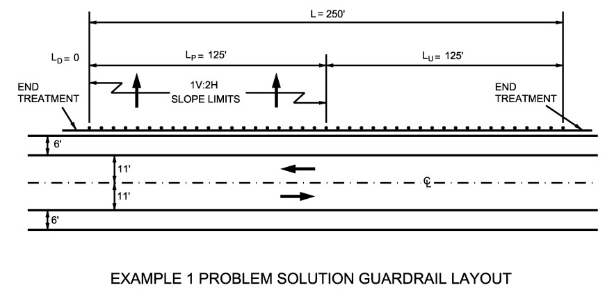
Figure 17-10: Example 1 Problem Solution Guard Fence Layout
Example Problem 2
Given
: A rural two-lane arterial highway containing a shoulder width of 8-ft and a current ADT of 3500 is illustrated in
. The areas of concern are bridge bents located 5-ft from the edge of shoulder. The side slopes are 1V:6H.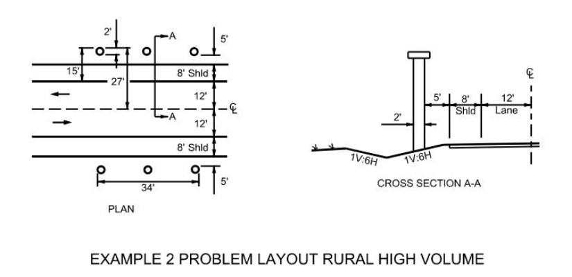
Figure 17-11: Example 2 Problem Layout Rural High Volume
Solution:
(Note, North is assumed to be on the top side of Plan view). Referring to
bridge piers within the clear zone (30-ft in this case) indicates guard fence placement for the north side of the roadway displayed in
. As shown in
the length of need is Ltotal
= Lu
+Lp
+Ld
. Lp
is 34-ft from the given information. Because the ADT is greater than 750,
and
are used to find Lu
and Ld
, respectively:Substituting in the equation, the upstream length (L
u
) is 116.5-ft if placement is at the shoulder edge.The downstream (westbound traffic) length of guard fence is determined by substituting into
:
L
d
is 65-ft as shown above, based on the shoulder edge placement. For westbound traffic, the centerline is the edge of the travel lane and thus guard fence offset (G) is 20-ft (12-ft lane plus 8-ft shoulder) from the edge of the travel lane.Total length of guard fence, L
u
+Lp
+Ld
, thus is 116.5-ft + 34-ft + 65-ft or 215.5-ft; or, rounded to an even length of guard fence, 225-ft.The solution for the south side of the roadway yields the same results; hence placement should be as shown in
.
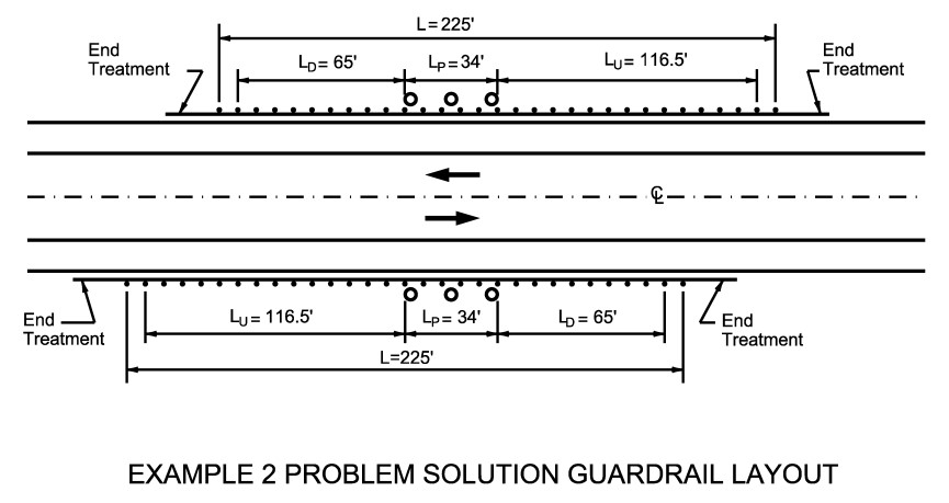
Figure 17-12: Example 2 Problem Solution Guard Fence Layout
Example Problem 3
Given:
A divided (76-ft median) highway with 4-ft left and 10-ft right shoulder widths is illustrated in
. The median slopes are 1V:10H, and the outside side slopes are 1V:6H. The cross-sectional design allows for the addition of a future lane on the median side of the present lanes. The areas of concern are overhead sign bridge supports offset 25-ft left and 18-ft right from edge of the travel lanes as shown below. The ADT is 10,000.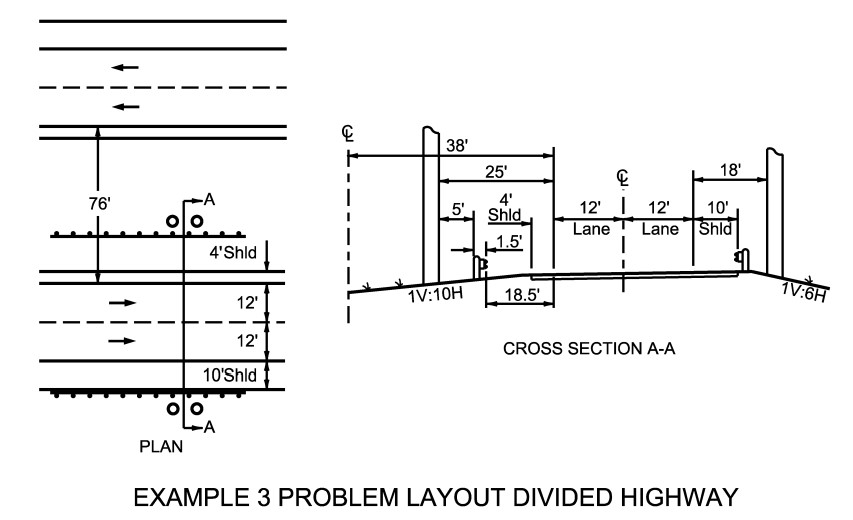
Figure 17-13: Example 3 Problem Layout Divided Highway
Solution:
Crash cushions in lieu of guard fence should be considered, particularly for facilities with higher than 10,000 ADT. For this example problem, assume crash cushions are not cost effective.Because the median is sloped at 1V:10H, as shown in
, guard fence may be placed thereon (see
). Therefore, place the guard fence such that the back of the posts is 5-ft in front of the median overhead sign bridge support to allow for deflection, i.e., 20-ft from the edge of the travel lanes (including the 1.5-ft from the back of the post to the face of the rail).
Referring to
, L
total
= Lu
+Lp
+Ld
. For one-way traffic operations, Ld
=0; furthermore, for the overhead sign bridge support Lp
=0.
is used to find Lu
because ADT is greater than 750:For the median side, L
u
= 65-ft (rounded to 75-ft to conform to even lengths of guard fence) based on parallel placement for the full length of need, and placement on the 1V:10H slope 5-ft in front of the fixed object. In contrast, parallel placement at the shoulder edge would have required over 200- ft of guard fence.For the right side of traffic, guard fence must be placed at the shoulder edge (see
). Substituting in
to determine L
u
:Using parallel placement for the entire length, L
u
= 111-ft (which should be rounded to 125-ft to conform to even lengths of guard fence).Using parallel placement for the entire length of guard fence for both the median and right side, placement is as shown in
.
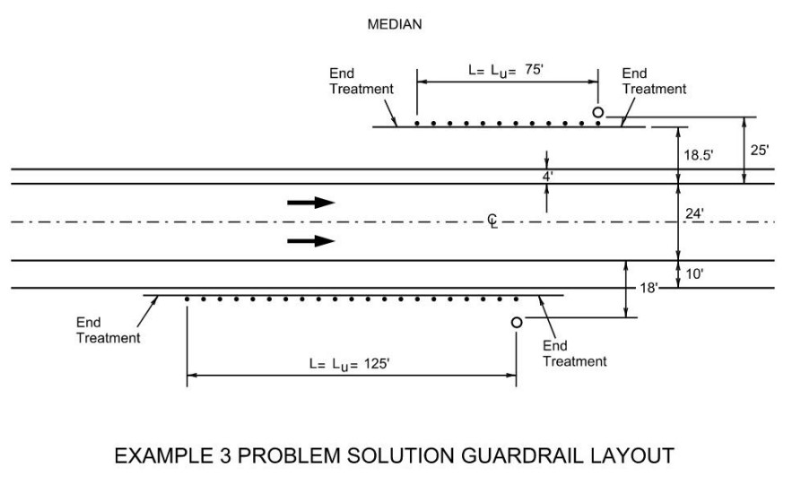
Figure 17-14: Example 3 Problem Solution Guardrail Layout