17.5 Guard Fence
Guard fence is considered a protective device for the traveling public and is used at points on the highway where a vehicle departure from the roadway would be a significant safety concern. Guard fence is designed to prevent impacts with roadside obstacles by redirecting the vehicle so that it continues to move at a reduced velocity in the original direction of traffic. The limits of guard fence to be installed are shown on the plans; however, they may be adjusted in the field after the grading is completed to assure compliance with standard guard fence applications. Refer to the respective TxDOT guard fence standards for specific guidance.
Guard fence should be installed in accordance with current roadway standards.
17.5.1 Blockouts
The guard fence is blocked out from the posts with routed timber or composite blockouts (nominally 6-in x 8-in x 14-in). These blockouts reduce vehicle snagging on the posts and the likelihood of a vehicle vaulting over the barrier by maintaining the rail height during the initial stages of post deflection.
It is acceptable to use double blockouts (up to 16-in in depth) to increase the post offset to avoid obstacles such as utilities. There is no limit to the number of posts that can have double blockouts installed, except terminals, unless approved by the manufacturer. Under special circumstances, such as avoiding buried obstacles that are not relocated, it is also acceptable to install triple blockouts (up to 24- in offset) for one post for every 75-ft of guard fence.
17.5.2 Structural Considerations of Guard Fence
Post spacing, rail shape and thickness, rail height, splice strength and location, post embedment, and rail anchorage are all key factors that influence the structural integrity of guard fence.
17.5.2.1 Post Spacing, Embedment, and Lateral Support
Typical post spacing is 6-ft 3-in for guard fence. Where guard fence is to be placed at or near the shoulder edge, it is recommended that the cross slope of the shoulder be projected, typically there should be no slope break within 2-ft beyond the back of the post location as shown in
, to provide lateral support for the posts. Locating the roadway cross slope/side slope hinge point behind the rail also provides a platform that increases vehicular stability in the event of impacts that straddle the guard fence.
Embedment depth is shown on the standard detail sheet for both timber and steel posts.
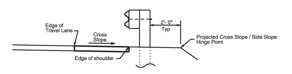
Figure 17-3: Lateral Support to Accommodate Guard Fence
17.5.2.2 Rail Element
Guard fence is fabricated in a w-beam shape to provide for bending strength. Nominal thickness of the rail is 10 or 12 gauge. End treatments, wingwalls, retaining walls, etc. provide firm rail anchorage. With full splice connections, the anchored rail has sufficient tensile and flexural strength to contain and redirect vehicles under nominal impact conditions. The standard length of the rail element is 25-ft, or 12.5-ft.
To ensure satisfactory performance for a range of vehicle sizes, rail should be mounted 25-in high as measured from shoulder surface, gutter pan, or widened crown to the center of the rail at the bolt. The rail element must be spliced midspan between the posts.
Pavement overlays effectively reduce existing rail height. The following guidelines must be followed:
- When rail height varies more than 3-in above and 3-in below the 31-in top of rail standard height, steps should be taken to restore the rail to the standard dimension to reduce the possibility of vehicular instability or vaulting or under riding the system;
- For existing 28-in rail systems, the rail height must not vary by more than 2-in above and ¼-in below the 28-in top of rail. Existing systems installed with a top rail height less than 27 ¾-in should be upgraded to current standards whenever impacted, repairs needed, or when maintenance budgets permit;
- When raising existing metal beam guard fence to the 31-in height (when splice is at the post location), the railing will also need to be adjusted longitudinally and an additional post or 9-ft 4 ½-in rail length will be needed to obtain the midspan splicing location; and
- Existing bridge transitions may need to be upgraded to current standards or adjusted with a new transition section to obtain the 31-in height. The end treatments may require new materials to adhere to the manufacturer’s specifications, such as the breakaway hole and angle strut locations.
17.5.3 Placement of Guard Fence
Guard fence should be installed in areas where the consequence of an errant vehicle leaving the roadway is judged to be more severe than impacting the guardrail.
The placement of guard fence pertains to the lateral and longitudinal position.
17.5.3.1 Lateral Placement at Shoulder Edge or Curb Face
Typically, the face of rail is placed at the shoulder edge or curb face throughout most of its length as shown in
.
Guard fence placed in the vicinity of curbs should be blocked out so that the face of curb is located directly below or behind the face of rail. Rail placed over curbs should be installed so that the post bolt is located 25-in above the gutter pan or roadway surface. For guidance in possible adjustments with respect to guard fence in the vicinity of curbs contact DES – Project Delivery Section.
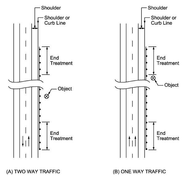
Figure 17-4: Placement at Shoulder Edge or Curb Face
17.5.3.2 Lateral Placement Away from the Shoulder Edge
In certain instances, it is desirable to place guard fence closer to the obstacle rather than at the shoulder edge or curb face. Guard fence placement guidance is shown in
. Placement in this manner can substantially reduce the length of rail required to shield a given obstacle and minimize the probability of impact, but undesirably, encroachment angles may increase. This manner of placement is most applicable to small areas of concern such as point type obstacles, overhead sign bridge supports, bridge piers, etc.
Care should be exercised in selecting placement location of guard fence with respect to slope conditions to reduce the risk of vaulting or impacting at an undesirable position by errant vehicles. Guard fence may be placed at any lateral location on a side slope only if the slope rate between the edge of the pavement and the face of the barrier is 1V:10H or flatter. Also, there should be no slope break within 2-ft beyond the back of the post location.
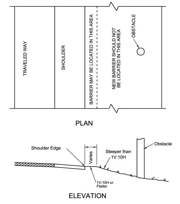
Figure 17-5: Location of Roadside Guard Fence
17.5.3.3 Deflection Considerations
Guard fence is a semi-rigid barrier system. The amount of dynamic deflection varies primarily with weight of impacting vehicle, its speed, and its encroachment angle. Guard fence should be laterally positioned to provide a clear shoulder width while maintaining a distance from a fixed object that is greater than the dynamic deflection of the rail. Based on crash test data, this barrier-to-object distance should be 4-ft minimum from the back of the post to fixed object or more as diagrammed in
.
A barrier-to-obstacle distance of 5-ft or more is desirable where conditions permit.
In certain circumstances in tightly constrained locations the deflection of the guard fence system can be reduced by reducing the post spacing to either 1/2 or 1/4 post spacing and applying an appropriate transition to the full post spacing as needed. Refer to
for specific guidance.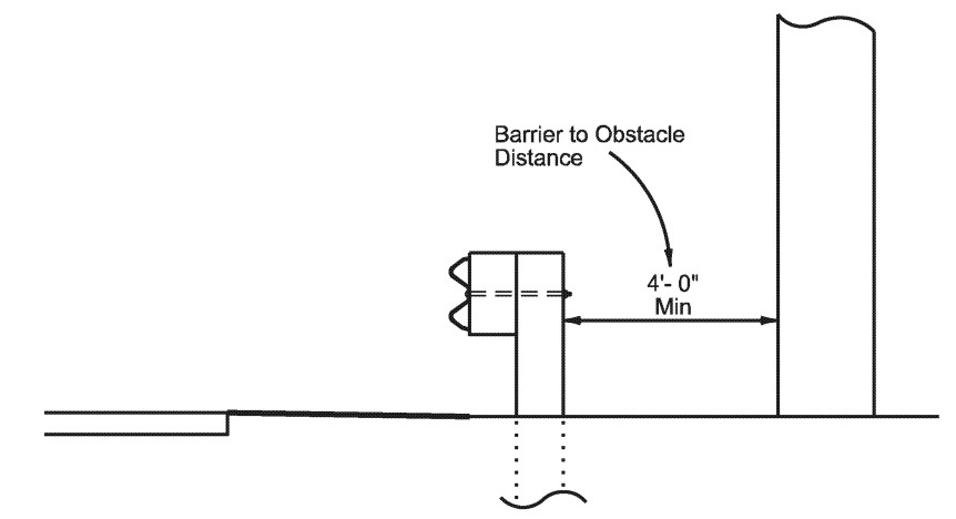
Figure 17-6: Allowance for Deflection of Guard Fence
17.5.4 End Treatment of Guard Fence
Providing appropriate end treatments is one of the most important considerations in the design of guard fence. An untreated guard fence will stop a vehicle abruptly and can penetrate the passenger compartment.
Guard fence systems must be anchored at both ends to acceptable end treatments, buried terminals, wingwalls, concrete traffic barriers, etc., so that full tensile strength of the rail may be developed.
Approved end treatments have been developed and are recommended for the upstream and downstream end of a guard fence system. These approved end treatments shall be used unless the guard fence terminal is located on the downstream end with respect to adjacent traffic of the guard fence and outside the clear zone for opposing traffic (see
). In that case a Downstream Anchor Terminal (DAT) end treatment without offset is acceptable for use