15.3.2 Four-Leg Interchanges
Four-leg interchanges can take a wide variety of forms. The choice of interchange is generally established after careful consideration of dominant traffic patterns and volumes, ROW requirements, and system considerations. The three primary types of four-leg interchanges are Diamond, Cloverleaf, and Directional.
15.3.2.1 Diamond Interchanges
The diamond interchange is the most common interchange, especially in urban areas since it requires less area than any other type. The diamond interchange is used almost exclusively for major-minor crossings since left-turn movements are made at-grade across conflicting traffic on the minor road. Separation between frontage road intersections in diamond interchanges in urban or suburban conditions should desirably be 300-ft as shown in
. Provide proper traffic signal timing if the 300-ft cannot be met.
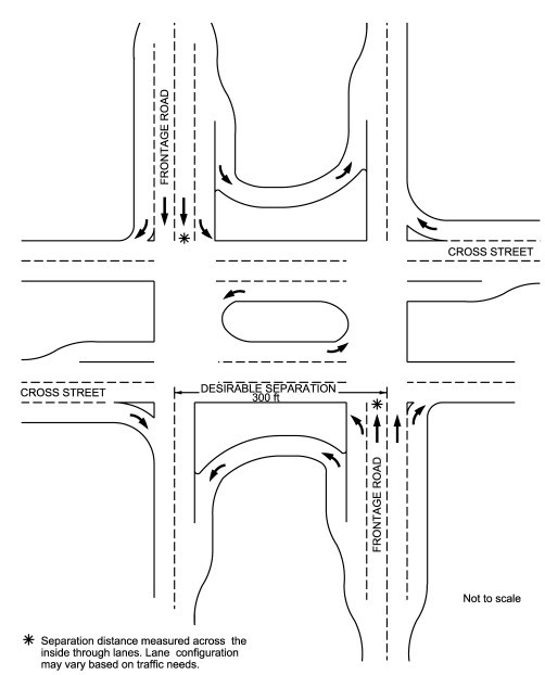
Figure 15-3: Separation of Frontage Roads in Diamond Interchanges
The diamond interchange may have several configurations, as discussed in the following paragraphs and shown in the figures below:
- Conventional diamond without frontage roads- The conventional diamond ( ) is the most common application of a diamond interchange. Traffic exits in advance of and close to the cross street. Entering vehicles quickly access the freeway just past the cross street. This design can result in vehicles backing up onto the freeway when long queues form on the ramp.
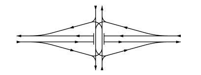
Figure 15-4: Conventional Diamond Interchange without Frontage Roads
- Conventional diamond with frontage roads- The conventional diamond with frontage roads ( ) is a common variation of a diamond interchange. Traffic exits in advance of and near the cross street. Entering vehicles quickly access the freeway past the cross street. Queues form on the ramp or frontage due to vehicles going through the intersection to gain access to the property located along the frontage road.
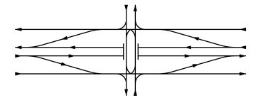
Figure 15-5: Conventional Diamond Interchange with Frontage Roads
- Spread diamond- The spread diamond ( ) moves the frontage roads outward to provide better intersection sight distance at the cross street. This design also provides improved operational characteristics with signalized intersections due to the separation between intersections. The additional ROW required may limit its usage.
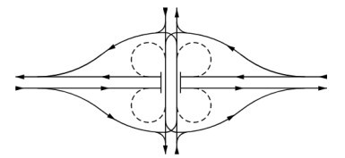
Figure 15-6: Spread Diamond Interchange
- X- pattern- The X-pattern interchange ( ) is used in locations with significant development along the frontage road. It provides access between interchanges and prevents exiting vehicles from backing up onto the freeway. However, entering vehicles may have to accelerate on an upgrade and exiting maneuvers occur just beyond the crest vertical curve where weaving also takes place. The "X" ramp pattern also encourages frontage road traffic to bypass the frontage road signal and weave with the mainlane traffic. The "X" ramp pattern may cause some drivers to miss an exit located well in advance of the cross street when the exit location is unexpected.
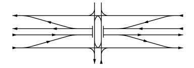
Figure 15-7: X-pattern Interchange
- Stacked diamond- Sometimes access to and from the mainlanes is needed on two closely spaced cross streets. Insufficient distance for consecutive entrance and exit ramps can be resolved by using grade separated or “braided” ramps, resulting in a “stacked diamond”. Both variations are shown in
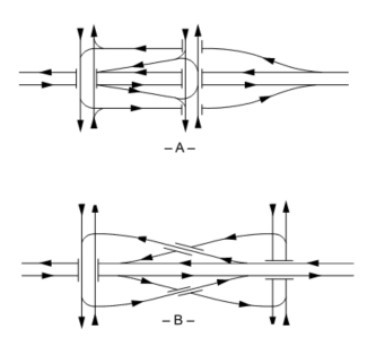
Figure 15-8: Stacked Diamond Interchange
Source: AASHTO A Policy on Geometric Design of Highways and Streets
- Split diamond- In some locations, it may be feasible and desirable to “split” the diamond by having one-way streets for the arterial movement ( ). This is especially true near central business districts where one-way street systems are common. However, the split diamond can also be used to accommodate two closely-spaced two-way arterial roadways crossing a freeway.
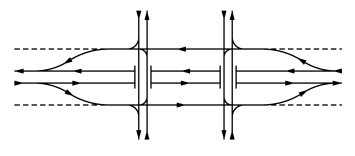
Figure 15-9: Split Diamond Interchange
- Split diamond with one-way cross streets and frontage roads- This layout is simplistic in layout and operation of both the crossroad and the at-grade terminals ( ). Traffic leaving the freeway is afforded easy access to return to the freeway and continue the journey in the same direction.
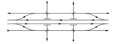
Figure 15-10: Split Diamond with One-way Cross Streets and Frontage Roads
- Diamond interchange with frontage roads and separate turnaround provisions- These are highly desirable if the cross street has heavy traffic volumes and there is considerable demand for the turnaround movement ( ). The turnaround roadways are adjacent to the cross street with additional width provided beneath the structure or, if the cross street overpasses the freeway, on top of the structure. See for more information on frontage road turnarounds and intersections.
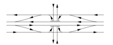
Figure 15-11: Diamond Interchange with Frontage Roads and Turnarounds
- Three level diamond- In urban areas, where the cross street carries a high volume of traffic, the three-level diamond interchange, illustrated in , may be warranted. The through movements of both the controlled access facility and the cross street flow is uninterrupted with only the turning movements requiring regulation by stop signs or traffic lights. This type of interchange is not usually recommended for use as the ultimate design at the crossing of two controlled access facilities because it requires left-turn interchanging traffic to negotiate three traffic signals or stop controls. However, as stage construction for a fully directional interchange between two controlled access facilities, the three-level diamond can be effective. Refer to .
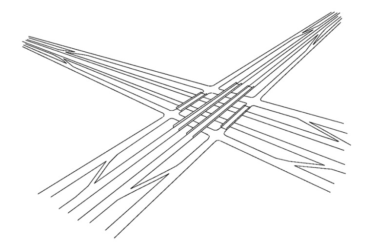
Figure 15-12: Three Level Diamond Interchange
- Single point diamond- A special type of freeway-to-arterial interchange has received attention during recent years and is worthy of discussion. Refer to for “single point diamond” (SPDI) or “single point urban” (SPUI) interchange. The primary features of an SPDI are that all four turning movements are controlled by a single traffic signal and opposing left turns operate to the left of each other. In this type of interchange, the freeway mainlanes may go either over or under the crossing arterial and the turn movements occur at-grade on the arterial, as illustrated in . This type of interchange has application only in specialized locations. Traffic operations and signalization must be carefully modeled prior to final design selection of the single point urban interchange.
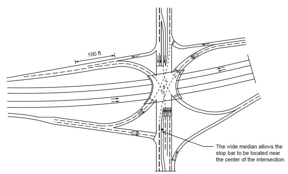
Figure 15-13: Split Point Diamond Interchange
- Three level stacked diamond- The three-level stacked diamond interchange is also an interchange requiring only one signalized intersection. In a sense, it is a three-level version of the “single point diamond” configuration, as illustrated in . This design grade separates both roadways and accommodates turning movements with signal operations requiring only one signalized intersection. The two-phase signal operation at the intersection typically provides a level of throughput on the turning movements between a conventional diamond interchange and a fully directional interchange. Furthermore, it works best at separating high arterial cross-street and freeway traffic. It has the same shortcomings as the “single point diamond” in the way it brings the left turn movements together.
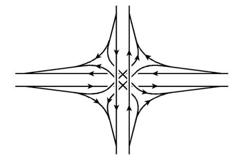
Figure 15-14: Three Level Stacked Diamond Interchange
As indicated in
, vehicles enter the intersection with oncoming vehicles to the right in contrast to the left as is the case on conventional diamond interchange intersections. Also, the design is less attractive with continuous frontage roads.
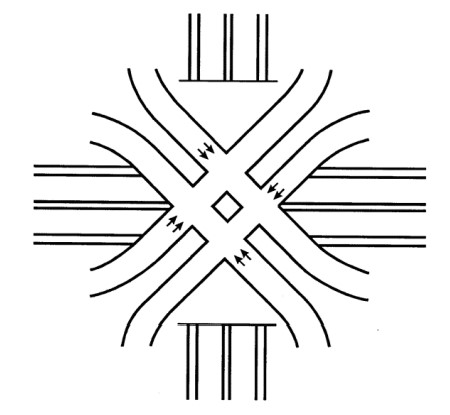
Figure 15-15: Three Level Stacked Diamond At-Grade Interchange
15.3.2.2 Cloverleaf Interchanges
Cloverleaf interchanges are very common in many states. These types of interchanges were popular in the early era of freeway construction but are usually no longer considered preferable for freeway-to-freeway movement, especially when interchange volumes are high.
However, in some instances they may be appropriate when a freeway interchanges with a non-controlled access facility in a location away from an urban or urbanizing area.
Cloverleafs should not be used where left-turn volumes are high, exceeding 1200 pcph
, since loop ramps are limited to one lane of operation and have restricted operating speeds.Primary disadvantages of the cloverleaf design include the following:
- Large ROW requirements;
- Capacity restrictions of loops, especially if truck volumes are significant;
- Short weaving length between loops; and
- Truck difficulty in weaving and accelerating.
When used, cloverleaf designs should include collector-distributor roads to provide more satisfactory operations, see
.
- Full cloverleaf- The four-quadrant, full cloverleaf, illustrated in , eliminates all left-turn conflicts through construction of a two-level interchange.
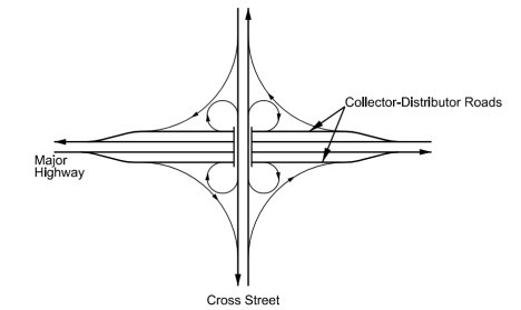
Figure 15-16: Full Cloverleaf Interchange
- Partial cloverleaf- A cloverleaf without ramps in all four quadrants, illustrated in , is sometimes used when site controls, such as railroads or streams running parallel to the cross street, limit the number of loops. Alternatively, this can be used when the left-turn conflicts caused by the absence of one or more loops are within tolerable limits. With such an arrangement, left-turn conflicts at the ramp intersections require that satisfactory approach sight distance be provided. Several variations on partial cloverleafs are referred to in
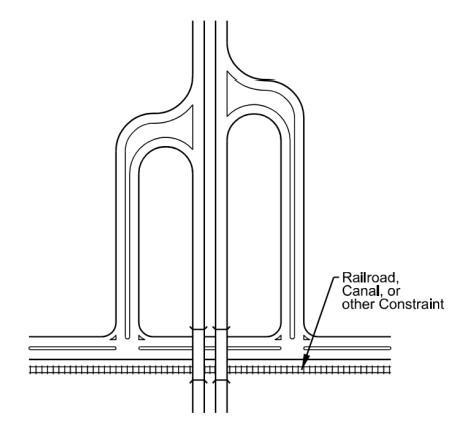
Figure 15-17: Partial Cloverleaf Interchange
15.3.2.3 Directional Interchanges
Interchanges that use direct or semi-direct connections for one or more left-turn movements are called “directional” interchanges (
and
).
When all turning movements travel on direct or semi-direct ramps or direct connections, the interchange is referred to as “fully directional”. These connections are used for important turning movements instead of loops to reduce travel distance, increase speed and capacity, reduce weaving and avoid loss of direction in traversing a loop. “Fully directional” interchanges are usually justified at the intersection of two freeways.
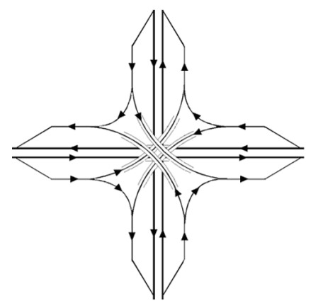
Figure 15-18: Four Level Fully Directional Interchange without Frontage Roads
- Four level without frontage roads- The four-level directional interchange as depicted in includes direct connections for all freeway-to-freeway movements, without continuation of any frontage roads through the interchange.
- Five level with frontage roads- In some instances, it may be desirable to continue the frontage roads through the interchange at the first or second level, producing a five-level directional interchange. Where frontage roads are made continuous through the interchange, the lower three levels are a three-level diamond configuration. Where stage construction is desired, the three-level diamond will adequately serve moderate traffic volumes until the upper two levels of direct connections are constructed to complete the five-level interchange. depicts a five-level interchange with frontage roads
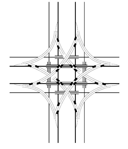
Figure 15-19: Five Level Fully Directional Interchange with Frontage Roads
- Turbine interchange- This interchange is an alternative four-way directional interchange. It requires fewer levels (usually two or three) while retaining direction ramps throughout. It features right-exit, left-turning ramps that sweep around the center of the interchange in a clockwise spiral. depicts a typical turbine interchange.
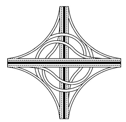
Figure 15-20: Turbine Interchange