14.10 Diverging Diamond Interchange (DDI)
14.10.1 Overview
The Diverging Diamond Interchange (DDI) is an interchange form where the two directions of traffic on the crossroad temporarily divide and cross to the opposite side to gain access to and from the freeway frontage roads more efficiently. The primary difference between a DDI and a conventional interchange is the design of directional crossovers on either side of the interchange. This eliminates the need for left-turning vehicles to cross the path of approaching vehicles. By shifting cross street traffic to the left side of the street between the signalized crossovers, vehicles on the crossroad making a left-turn on to or off of ramps, or frontage roads, do not conflict with vehicles approaching from other directions. TxDOT has adopted the
as the primary source for DDI guidelines.
depicts a schematic concept of the DDI Interchange configuration.
.png/_jcr_content/renditions/original)
Figure 14-38: Diverging Diamond Interchange Concpet (DDI)
Source: Virginia DOT, used by permission
The information contained in this section is considered a companion to the FHWA Guide and is intended to document TxDOT’s suggested approach to DDI design.
Documented benefits of a DDI include:
- Capacity improvements with two-phase signal configurations;
- Safety improvements due to a reduction in the number of conflict points; and
- Possible lower costs due to a smaller footprint, shorter construction time, and the possibility of being able to salvage existing bridge structures.
Conditions where a DDI may not be suitable include:
- Densely developed areas –DDI’s can restrict access to existing developments due to the crossovers near the interchange; and
- Inadequate driver familiarity –DDI’s require public involvement and education as well as significant signage to assist drivers navigating the interchange.
shows the design characteristics and key features of the DDI.
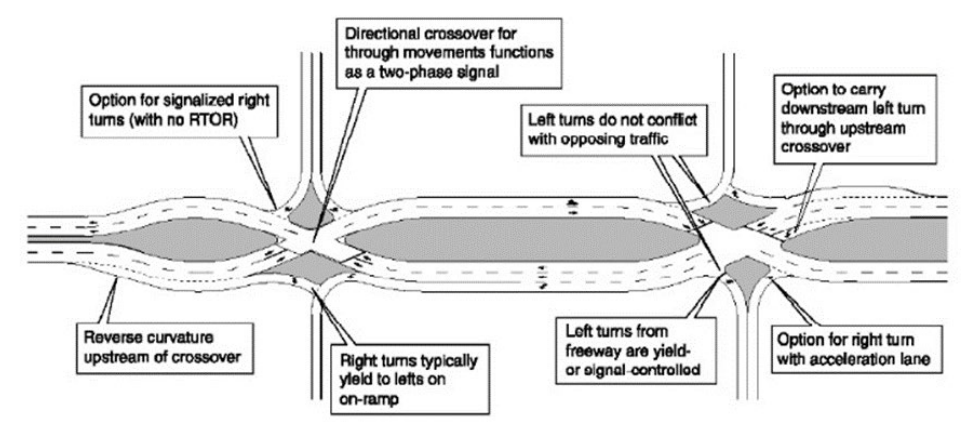
Figure 14-39: Key Characteristics of a DDI
Source: FHWA DDI Informational Guide
14.10.2 Design Considerations
Development of functional geometrics are central to safe and efficient operation of a DDI. The most common design vehicle used at DDI facilities is the WB-67. In more urbanized areas, it may be appropriate to use smaller design vehicles, such as the WB-62TX or WB40. The anticipated truck movements, staying in-lane through the DDI, should be determined and AutoTURN (or a similar tool) used to assess vehicle encroachments within the DDI. The largest truck movements may be accommodated by using a roll down curb in turning areas. The design speed of the DDI affects the reverse curve radii through the two intersection crossovers and should typically range from 25 to 35 mph (
and
for corresponding curve radii values). The DDI profile should be relatively flat to increase driver sight distance. A tangent section is recommended before and after the crossovers to minimize the likelihood of wrong way maneuvers into opposing lanes, and the recommended crossover angle is 40-50 degrees or greater (see
and
). A consolidated ramp terminal intersection with crossover is desired over separated ramp terminal intersection elements (see
).
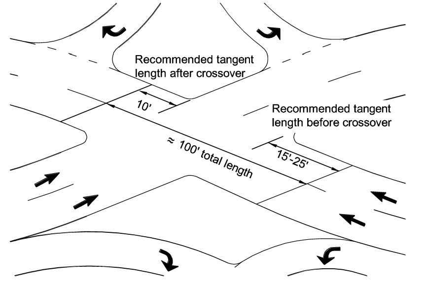
Figure 14-40: Tangent Length Approaching and Departing the Crossover
Source: FHWA DDI Informational Guide
Curve radii approaching and following the DDI crossover generally range from 150-ft to 300-ft. At the crossover, the greater the crossing angle, the less “different” the intersection will seem. FHWA’s Intersection and Interchange Geometrics (IIG) Workshop, May 2016, recommends a crossover angle of 40 to 50 degrees. The 2016 IIG Workshop also noted the following regarding low crossover angles:
- Low crossover angles may increase the likelihood for wrong-way maneuvers into the opposing lanes; and
- Low angles increase distances and increase signal clearance time.
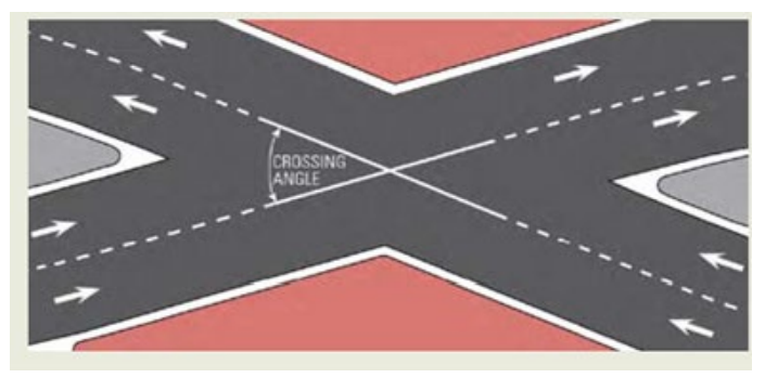
Figure 14-41: DDI Crossover Geometry (Crossing Angle)
Source: FHWA Intersection and Interchange Geometrics (IIG) Workshop (May 2016)
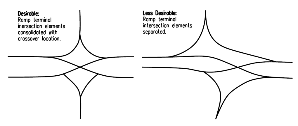
Figure 14-42: Consolidating the Ramp Terminal Intersection
Source: FHWA DDI Informational Guide
14.10.3 Sight Distance
Drivers approaching or departing an intersection must have an unobstructed view of traffic control devices and sufficient length along the crossroad to safely navigate the intersection. Insufficient sight distance is a significant factor in street crashes and near collisions. As with any other intersection, DDI intersections must provide stopping sight distance (SSD) and intersection sight distance (ISD). Sight distances must be checked for these conflict areas: walls, railings, tall landscaping, or other obstructions that may limit sight distance. Intersection sight distance may also be limited by barriers or other obstacles between the crossovers.
Due to their curvilinear alignment, DDIs have special considerations that need to be reviewed and coordinated closely with the horizontal alignment. Primary considerations for vertical alignment at DDIs include:
- Crest vertical curve on the overcrossing -A crest vertical curve on an overcrossing may potentially mask the turning roadway alignment to the crossover;
- Skew in an overcrossing -A crest vertical curve and skew angle can also result in reduced visibility to the crosswalk across the left-turning roadway; and
- Crosswalk visibility -The relatively sharp horizontal curve to the left and bridge parapet can obscure views to a user waiting at the pedestrian crossing
Refer to
for additional information regarding sight distance considerations.
14.10.4 Horizontal Alignment Alternatives
There are three alignment alternatives resulting in a minimum cross-section along the cross road regardless of whether the facility is an over-or under pass. There are two types of alignments: Symmetrical Alignment and the Shifted Alignment.
shows an example of symmetrical and shifted alignments. This results in distances of 600-ft to 750-ft between crossovers. If the distance between crossovers can be reduced, it can boost traffic operations and limit the amount of ROW needed.
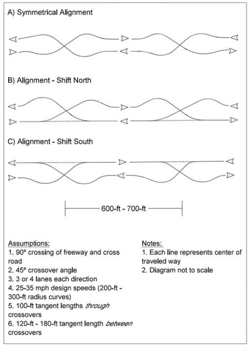
Figure 14-43: Alignment Alternatives
Eliminating a few reverse curves can reduce the spacing between crossovers.
shows alignment alternatives where the number of reverse curves has been reduced with a resultant increase in median width. This results in distances of 400-ft to 500-ft between crossovers. Chapter 7 of
provides additional information on horizontal alignment options.
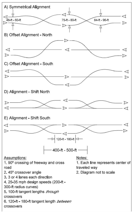
Figure 14-44: Reduced Reverse Curves in Alignment Alternatives
14.10.5 Auxiliary Lanes
Auxiliary lanes can aid weaving traffic at a DDI interchange, smooth traffic flow, provide added capacity, and improve overall safety.
through
show examples of auxiliary lanes at a DDI interchange. Chapter 7 of
provides additional information on auxiliary lanes.
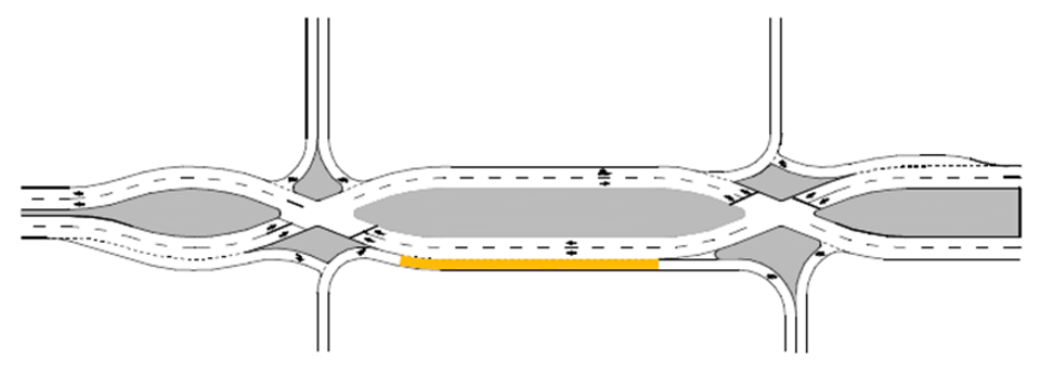
Figure 14-45: Auxiliary Left-Turn Lane Between Crossovers (Not Preferred)
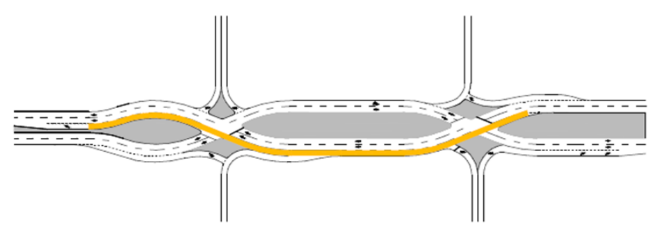
Figure 14-46: Auxiliary Left-Turn Lane Developed Prior to the First Crossover
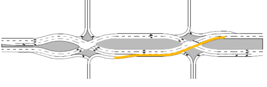
Figure 14-47: Auxiliary Lane, Shared Left and Through, Developed Prior to the First Crossover
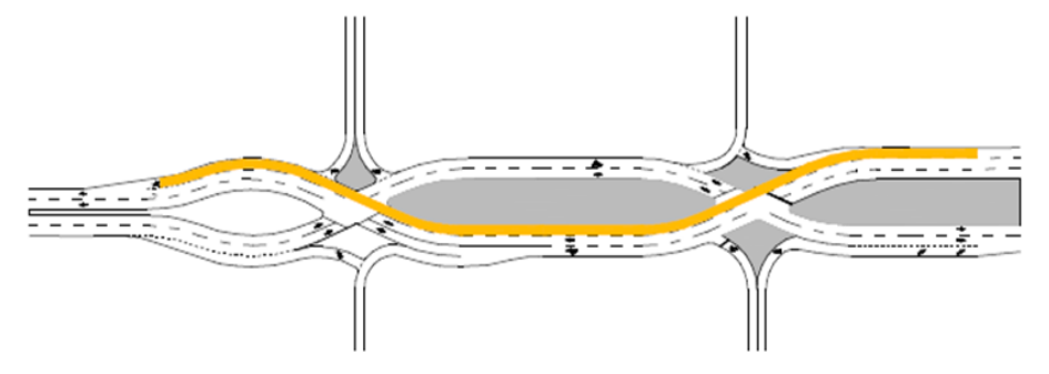
Figure 14-48: Auxiliary Through Lane Developed Prior to the First Crossover
14.10.6 Ramp Terminals
Ramp Terminal geometry is discussed in
, Section 6.4.8 and is shown in
.
The contemporary configuration shown in
is considered to be the safer solution for DDI ramp terminal geometry based on the enhanced reduction in vehicle speed while offering greater view angles that require drivers to turn their heads to less of a degree while trying to identify oncoming traffic.
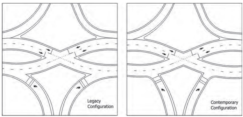
Figure 14-49: Ramp Terminal Geometry at a DDI
14.10.7 Pedestrian and Bicyclist Considerations
DDIs have many benefits for pedestrians which include:
- Allowing more crossing time per phase due to the two-phase signal operations;
- Crossing only one direction of traffic resulting in reduced conflicts; and
- Fewer travel lanes for a pedestrian to cross.
DDIs provide the option to direct pedestrians to either the outside of the intersection or to a center walkway. The wide area between opposing traffic allows the opportunity for a large sidewalk down the center that can be bordered by concrete barrier for additional protection and channelization for pedestrians. Pedestrian facilities on the inside minimize conflicts with traffic turning left to and from the freeway and allow the crossing of the interchange in all directions. When placing the pedestrian sidewalk along the outside, important considerations are: the location of the crosswalk with respect to the bridge structure or other sight obstructions to maintain good visibility for both the pedestrians and vehicles and designing the turning radii to reduce speeds in the vicinity of pedestrians.
and
depict the inside and outside pedestrian sidewalk options, respectively.
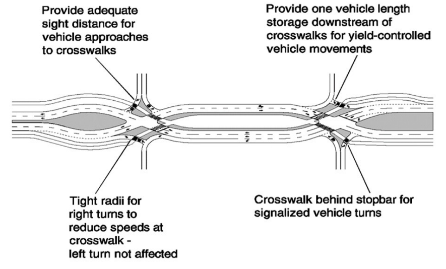
Figure 14-50: Pedestrian-focused DDI – Center Walkway
Source: FHWA DDI Informational Guide
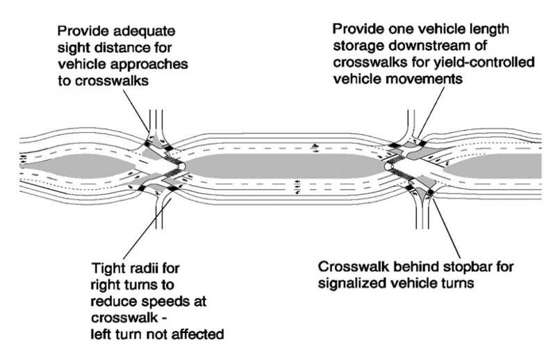
Figure 14-51: Pedestrian-focused DDI – Outside Walkway
Source: FHWA DDI Informational Guide
For bicyclists, the design should focus on minimizing bicycle conflicts with motor vehicles, providing adequate lateral space between vehicles and bicycles, minimizing speed differential between bicycle and vehicles, and managing bicycle-pedestrian conflicts. The 2 primary options for bicyclists on a cross street through a DDI are:
- A marked bicycle lane through the DDI -If a separate bicycle lane is provided, the preference is to locate it to the right of the vehicular traffic. Bicycle lane widths of 5-ft to 7-ft are recommended through the DDI. See ; and
- A separated sidewalk or wider shared-use path -This would typically entail the bicyclist proceeding through the DDI in the same area designated for pedestrians.
Ultimately, a thorough site assessment, an assessment of anticipated bicycle and pedestrian volumes, and an assessment of projected origins and destinations for pedestrians and bicyclists should be conducted to determine the preferred method of movement through the DDI.
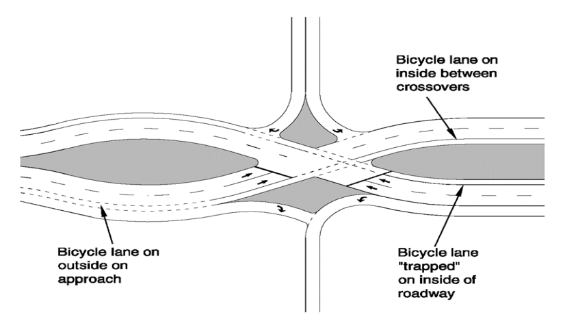
Figure 14-52: Schematic for bicycle lane placement on right side of vehicular traffic
Source: FHWA DDI Informational Guide
14.10.8 Access Management
DDI intersections require full access control through the interchange. A traffic simulation should be conducted to determine the impacts and any needed mitigation for adjacent and nearby intersections in the corridor. Possible disadvantages of a DDI include the following:
- Will not allow exit ramp to entrance ramp movements;
- Through movements along the frontage road can only be accommodated via bypass lanes or collector-distributor systems;
- May require modifications to nearby signalized intersections;
- Additional access control beyond the interchange may be needed to prevent weaving maneuvers;
- May require the relocating or removal of adjacent streets/driveways to accommodate crossover and reverse curves; and
- Removes driveway access for corner development.
Refer to the
for additional guidance with respect to access management.
14.10.9 Safety
DDIs have safety benefits due to reduced conflict points, especially crossing conflict points, resulting in fewer severe crashes. They also decrease the likelihood of wrong-way maneuvers onto the intersecting expressway. Caution should be exercised when allowing right-turn-on-red and left-turn-on-red maneuvers, as drivers may look to the wrong side of the road for oncoming traffic. For additional information on safety, refer to the
.
14.10.10 Operations
DDI operations may vary slightly based on location and traffic demand. There are three potential phasing schemes:
- Two-critical movement phasing;
- Three-critical movement phasing; and
- Four critical movement phasing.
Signal timing and phasing of the adjacent intersections must be coordinated to provide appropriate capacity to the DDI. Refer to the
for more information on operations.
14.10.11 Traffic Control Devices
DDIs require clear traffic control devices to guide drivers through the interchange. The four main objectives of traffic control devices in DDIs are:
- Priority –describes which movement has the ROW;
- Directional guidance –informs drivers about upcoming turning movements;
- Lane choice –communicates to drivers which lane to choose prior to entering the DDI; and
- Information –about other aspects of the interchange. Care must be used when providing informational signs to avoid distracting drivers.
Refer to
for more information on traffic control devices. The
remains the primary source for traffic control device standards.
14.10.12 Illumination
At a minimum, safety lighting should be provided for DDIs in rural locations. Complete illumination systems should be considered at all DDIs to enhance visibility and safety. Refer to TxDOT’s
for additional information and design standards.