Section 3: Roadside Channel Design
Roadside Drainage Channels
According to the AASHTO Roadside Design Guide, roadside drainage channel is an open
channel usually paralleling the highway embankment and within limits of the ROW. The
primary function of a drainage channel is to collect surface runoff from the roadway and
areas that drain to the ROW and to convey the accumulated runoff to acceptable outlet
points. Drainage channels must be designed to carry the design runoff and to accommodate
excessive storm water with minimal roadway flooding or damage. The design frequency
should correspond with the storm drain frequency. For details of roadway safety design
which governs ditch shape design, see the Roadway Design Manual, Chapter 2, Section 6,
, and
, and Chapter 2, Section 7,
. Where the Roadway Design Manual
requirements can’t be met, the channel will have to be enclosed in a pipe or box. See
Chapter 10,
.
Channel Linings
Channel lining may be desirable or necessary to minimize maintenance, resist the erosive forces of flowing water, improve hydraulic efficiency, and/or limit the channel size for right-of-way or safety considerations. The considerations of flow volumes, topography, and soil conditions may dictate the channel lining material to be used. Wherever possible, highway drainage channel design should make use of native, natural materials such as grass, crushed rock, and earth. Other types of materials for reasons of hydraulics, economics, safety, aesthetics, and environment may be considered.
The following section contains a short discussion on channel linings. For comprehensive descriptions, advantages, and disadvantages of different types of channel linings, refer to the FHWA Hydraulic Engineering Circular No. 15 (
).
Rigid versus Flexible Lining
Engineers may design roadside channels with rigid or flexible linings. Flexible linings in channels conform better to a changing channel shape than rigid linings. However, a rigid lining may resist an erosive force of high magnitude better than a flexible one.
The following types of rigid linings are common:
- cast-in-place concrete
- soil cement
- fabric form work systems for concrete
- grouted riprap.
Rigid channel linings have the following disadvantages when compared to natural or earth-lined channels:
- Initial construction cost of rigid linings is usually greater than the cost of flexible linings.
- Maintenance costs may also be high because rigid linings are susceptible to damage by undercutting, hydrostatic uplift, and erosion along the longitudinal interface between the lining and the unlined section.
- Inhibition of natural infiltration in locations where infiltration is desirable or permissible.
- Smooth linings usually cause high flow velocities with scour occurring at the terminus of the sections unless controlled with riprap or other energy dissipating devices
- Contaminants may be transported to the receiving waters in areas where water quality considerations are of major concern. A vegetative or flexible type of lining may filter the contaminants from the runoff.
Permanent flexible linings include the following:
- rock riprap
- wire enclosed riprap (gabions)
- vegetative lining
- geotextile fabrics.
Flexible linings generally have the following advantages:
- less costly to construct
- have self-healing qualities that reduce maintenance costs
- permit infiltration and exfiltration
- present a more natural appearance and safer roadsides.
Various species of grass may be used as permanent channel lining if flow depths, velocities, and soil types are within acceptable tolerances for vegetative lining. The turf may be established by sodding or seeding. Sod is usually more expensive than seeding, but it has the advantage of providing immediate protection. Some type of temporary protective covering is often required for seed and topsoil until vegetation becomes established.
The following are classified as temporary flexible linings:
- geotextile fabrics
- straw with net
- curled wood mat
- jute, paper, or synthetic net
- synthetic mat
- fiberglass roving.
Temporary channel lining and protective covering may consist of jute matting, excelsior mats, or fiberglass roving. Straw or wood-chip mulch tacked with asphalt is usually not well suited for channel invert lining but may be used for side slopes. Geotextile materials, known as soil stabilization mats, may be used for protective linings in ditches and on side slopes. These materials are not biodegradable and serve as permanent soil reinforcement while enhancing the establishment of vegetation.
Channel Lining Design Procedure
Use the following design procedure for roadside channels. Even though each project is unique, these six basic design steps normally apply:
- Establish a roadside plan. Collect available site data:
- Obtain or prepare existing and proposed plan/profile layouts including highway, culverts, bridges, etc.
- Determine and plot on the plan the locations of natural basin divides and roadside channel outlets.
- Lay out the proposed roadside channels to minimize diversion flow lengths.
- Establish cross section geometry: Identify features that may restrict cross section design including right-of-way limits, trees or environmentally sensitive areas, utilities, and existing drainage facilities. Provide channel depth adequate to drain the subbase and minimize freeze-thaw effects. Choose channel side slopes based on the following geometric design criteria: safety, economics, soil, aesthetics, and access. Establish the bottom width of trapezoidal channel.
- Determine initial channel grades. Plot initial grades on plan-profile layout (slopes in roadside ditch in cuts are usually controlled by highway grades) by establishing a minimum grade to minimize ponding and sediment accumulation, considering the influence of type of lining on grade, and where possible, avoiding features that may influence or restrict grade, such as utility locations.
- Check flow capacities, and adjust as necessary. Compute the design discharge at the downstream end of a channel segment (see Chapter 5). Set preliminary values of channel size, roughness, and slope. Determine the maximum allowable depth of channel including freeboard. Check the flow capacity using Manning’s Equation for Uniform Flow and single-section analysis (see and Chapter 6). If the capacity is inadequate, possible adjustments are as follows:
- increase bottom width
- make channel side slopes flatter
- make channel slope steeper
- provide smoother channel lining
- install drop inlets and a parallel storm drain pipe beneath the channel to supplement channel capacity
- provide smooth transitions at changes in channel cross sections
- provide extra channel storage where needed to replace floodplain storage or to reduce peak discharge
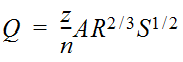 Equation 7-1.where:
- Q= discharge (cfs or m3/s)
- A= cross-sectional area of flow (sq. ft. or m2)
- R= hydraulic radius (ft. or m)
- Z = conversion factor; 1.486 for English units, and 1.0 for metric
- Determine channel lining or protection needed. Calculate uniform flow depth (ymin ft. or m) at design discharge using the . Compute maximum shear stress at normal depth (see Equation 7‑2 and Equation 7-3). Select a lining and determine the permissible shear stress (in lbs./sq.ft. or N/m2) using the tables titled for Lining Materials and for Various Linings. If τd< τp, then the lining is acceptable. Otherwise, consider the following options: choose a more resistant lining, use concrete or gabions or other more rigid lining as full lining or composite, decrease channel slope, decrease slope in combination with drop structures, or increase channel width or flatten side slopes.
- Analyze outlet points and downstream effects. Identify any adverse impacts to downstream properties that may result from one of the following at the channel outlet: increase or decrease in discharge, increase in velocity of flow, confinement of sheet flow, change in outlet water quality, or diversion of flow from another watershed. Mitigate any adverse impacts identified in the previous step. Possibilities include enlarging the outlet channel or installing control structures to provide detention of increased runoff in channel, installing velocity control structures, increasing capacity or improving the lining of the downstream channel, installing sedimentation/infiltration basins, installing sophisticated weirs or other outlet devices to redistribute concentrated channel flow, and eliminating diversions that result in downstream damage and that cannot be mitigated in a less expensive fashion.
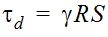
Equation 7-2.
where:
- τ = average shear stress at normal depth (lb./sq.ft. or N/m2)
- γ = unit weight of water (62.4 lb./ft.3or 9810 N./m.2)
- R = hydraulic radius (ft. or m.) at uniform depth (ym)
- S = channel slope (ft./ft. or m./m.)
The maximum shear stress for a straight channel occurs on the channel bed.
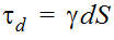
Equation 7-3.
where:
- τd= maximum sheer stress (lb./sq ft. or N/m2)
- γ = unit weight of water (62.4 lb./ft.3or 9810 N./m.2)
- d = maximum depth of flow (ft. or m.)
- S = channel slope (ft./ft. or m./m.)
Retardance Class | Cover | Condition |
A | Weeping Lovegrass | Excellent stand, tall (average 30 in. or 760 mm) |
Yellow Bluestem Ischaemum | Excellent stand, tall (average 36 in. or 915 mm) | |
B | Kudzu | Very dense growth, uncut |
Bermuda grass | Good stand, tall (average 12 in. or 305 mm) | |
Native grass mixture little bluestem, bluestem, blue gamma, other short and long stem midwest grasses | Good stand, unmowed | |
Weeping lovegrass | Good Stand, tall (average 24 in. or 610 mm) | |
Lespedeza sericea | Good stand, not woody, tall (average 19 in. or 480 mm) | |
Alfalfa | Good stand, uncut (average 11 in or 280 mm) | |
Weeping lovegrass | Good stand, unmowed (average 13 in. or 330 mm) | |
Kudzu | Dense growth, uncut | |
Blue gamma | Good stand, uncut (average 13 in. or 330 mm) | |
C | Crabgrass | Fair stand, uncut (10-to-48 in. or 55-to-1220 mm) |
Bermuda grass | Good stand, mowed (average 6 in. or 150 mm) | |
Common lespedeza | Good stand, uncut (average 11 in. or 280 mm) | |
Grass-legume mixture: summer (orchard grass redtop, Italian ryegrass, and common lespedeza) | Good stand, uncut (6-8 in. or 150-200 mm) | |
Centipedegrass | Very dense cover (average 6 in. or 150 mm) | |
Kentucky bluegrass | Good stand, headed (6-12 in. or 150-305 mm) | |
D | Bermuda grass | Good stand, cut to 2.5 in. or 65 mm |
Common lespedeza | Excellent stand, uncut (average 4.5 in. or 115 mm) | |
Buffalo grass | Good stand, uncut (3-6 in. or 75-150 mm) | |
Grass-legume mixture: fall, spring (orchard grass Italian ryegrass, and common lespedeza | Good Stand, uncut (4-5 in. or 100-125 mm) | |
Lespedeza sericea | After cutting to 2 in. or 50 mm (very good before cutting) | |
E | Bermuda grass | Good stand, cut to 1.5 in. or 40 mm |
Bermuda grass | Burned stubble |
Protective Cover | (lb./sq.ft.) | t p (N/m2 ) |
Retardance Class A Vegetation (See the “Retardation Class for Lining Materials” table above) | 3.70 | 177 |
Retardance Class B Vegetation (See the “Retardation Class for Lining Materials” table above) | 2.10 | 101 |
Retardance Class C Vegetation (See the “Retardation Class for Lining Materials” table above) | 1.00 | 48 |
Retardance Class D Vegetation (See the “Retardation Class for Lining Materials” table above) | 0.60 | 29 |
Retardance Class E Vegetation (See the “Retardation Class for Lining Materials” table above) | 0.35 | 17 |
Woven Paper | 0.15 | 7 |
Jute Net | 0.45 | 22 |
Single Fiberglass | 0.60 | 29 |
Double Fiberglass | 0.85 | 41 |
Straw W/Net | 1.45 | 69 |
Curled Wood Mat | 1.55 | 74 |
Synthetic Mat | 2.00 | 96 |
Gravel, D 50 = 1 in. or 25 mm | 0.40 | 19 |
Gravel, D 50 = 2 in. or 50 mm | 0.80 | 38 |
Rock, D 50 = 6 in. or 150 mm | 2.50 | 120 |
Rock, D 50 = 12 in. or 300 mm | 5.00 | 239 |
6-in. or 50-mm Gabions | 35.00 | 1675 |
4-in. or 100-mm Geoweb | 10.00 | 479 |
Soil Cement (8% cement) | >45 | >2154 |
Dycel w/out Grass | >7 | >335 |
Petraflex w/out Grass | >32 | >1532 |
Armorflex w/out Grass | 12-20 | 574-957 |
Erikamat w/3-in or 75-mm Asphalt | 13-16 | 622-766 |
Erikamat w/1-in. or 25 mm Asphalt | <5 | <239 |
Armorflex Class 30 with longitudinal and lateral cables, no grass | >34 | >1628 |
Dycel 100, longitudinal cables, cells filled with mortar | <12 | <574 |
Concrete construction blocks, granular filter underlayer | >20 | >957 |
Wedge-shaped blocks with drainage slot | >25 | >1197 |
Trial Runs
To optimize the roadside channel system design, make several trial runs before a final design is achieved. Refer to
for more information on channel design techniques and considerations.