Channel Lining Design Procedure
Use the following design procedure for roadside channels. Even though each project is unique, these six basic design steps normally apply:
- Establish a roadside plan. Collect available site data:
- Obtain or prepare existing and proposed plan/profile layouts including highway, culverts, bridges, etc.
- Determine and plot on the plan the locations of natural basin divides and roadside channel outlets.
- Lay out the proposed roadside channels to minimize diversion flow lengths.
- Establish cross section geometry: Identify features that may restrict cross section design including right-of-way limits, trees or environmentally sensitive areas, utilities, and existing drainage facilities. Provide channel depth adequate to drain the subbase and minimize freeze-thaw effects. Choose channel side slopes based on the following geometric design criteria: safety, economics, soil, aesthetics, and access. Establish the bottom width of trapezoidal channel.
- Determine initial channel grades. Plot initial grades on plan-profile layout (slopes in roadside ditch in cuts are usually controlled by highway grades) by establishing a minimum grade to minimize ponding and sediment accumulation, considering the influence of type of lining on grade, and where possible, avoiding features that may influence or restrict grade, such as utility locations.
- Check flow capacities, and adjust as necessary. Compute the design discharge at the downstream end of a channel segment (see Chapter 5). Set preliminary values of channel size, roughness, and slope. Determine the maximum allowable depth of channel including freeboard. Check the flow capacity using Manning’s Equation for Uniform Flow and single-section analysis (see and Chapter 6). If the capacity is inadequate, possible adjustments are as follows:
- increase bottom width
- make channel side slopes flatter
- make channel slope steeper
- provide smoother channel lining
- install drop inlets and a parallel storm drain pipe beneath the channel to supplement channel capacity
- provide smooth transitions at changes in channel cross sections
- provide extra channel storage where needed to replace floodplain storage or to reduce peak discharge
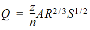 Equation 7-1.where:
- Q= discharge (cfs or m3/s)
- A= cross-sectional area of flow (sq. ft. or m2)
- R= hydraulic radius (ft. or m)
- Z = conversion factor; 1.486 for English units, and 1.0 for metric
- Determine channel lining or protection needed. Calculate uniform flow depth (ymin ft. or m) at design discharge using the . Compute maximum shear stress at normal depth (see Equation 7‑2 and Equation 7-3). Select a lining and determine the permissible shear stress (in lbs./sq.ft. or N/m2) using the tables titled for Lining Materials and for Various Linings. If τd< τp, then the lining is acceptable. Otherwise, consider the following options: choose a more resistant lining, use concrete or gabions or other more rigid lining as full lining or composite, decrease channel slope, decrease slope in combination with drop structures, or increase channel width or flatten side slopes.
- Analyze outlet points and downstream effects. Identify any adverse impacts to downstream properties that may result from one of the following at the channel outlet: increase or decrease in discharge, increase in velocity of flow, confinement of sheet flow, change in outlet water quality, or diversion of flow from another watershed. Mitigate any adverse impacts identified in the previous step. Possibilities include enlarging the outlet channel or installing control structures to provide detention of increased runoff in channel, installing velocity control structures, increasing capacity or improving the lining of the downstream channel, installing sedimentation/infiltration basins, installing sophisticated weirs or other outlet devices to redistribute concentrated channel flow, and eliminating diversions that result in downstream damage and that cannot be mitigated in a less expensive fashion.
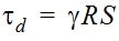
Equation 7-2.
where:
- τ = average shear stress at normal depth (lb./sq.ft. or N/m2)
- γ = unit weight of water (62.4 lb./ft.3or 9810 N./m.2)
- R = hydraulic radius (ft. or m.) at uniform depth (ym)
- S = channel slope (ft./ft. or m./m.)
The maximum shear stress for a straight channel occurs on the channel bed.
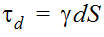
Equation 7-3.
where:
- τd= maximum sheer stress (lb./sq ft. or N/m2)
- γ = unit weight of water (62.4 lb./ft.3or 9810 N./m.2)
- d = maximum depth of flow (ft. or m.)
- S = channel slope (ft./ft. or m./m.)
Retardance Class | Cover | Condition |
A | Weeping Lovegrass | Excellent stand, tall (average 30 in. or 760 mm) |
Yellow Bluestem Ischaemum | Excellent stand, tall (average 36 in. or 915 mm) | |
B | Kudzu | Very dense growth, uncut |
Bermuda grass | Good stand, tall (average 12 in. or 305 mm) | |
Native grass mixture little bluestem, bluestem, blue gamma, other short and long stem midwest grasses | Good stand, unmowed | |
Weeping lovegrass | Good Stand, tall (average 24 in. or 610 mm) | |
Lespedeza sericea | Good stand, not woody, tall (average 19 in. or 480 mm) | |
Alfalfa | Good stand, uncut (average 11 in or 280 mm) | |
Weeping lovegrass | Good stand, unmowed (average 13 in. or 330 mm) | |
Kudzu | Dense growth, uncut | |
Blue gamma | Good stand, uncut (average 13 in. or 330 mm) | |
C | Crabgrass | Fair stand, uncut (10-to-48 in. or 55-to-1220 mm) |
Bermuda grass | Good stand, mowed (average 6 in. or 150 mm) | |
Common lespedeza | Good stand, uncut (average 11 in. or 280 mm) | |
Grass-legume mixture: summer (orchard grass redtop, Italian ryegrass, and common lespedeza) | Good stand, uncut (6-8 in. or 150-200 mm) | |
Centipedegrass | Very dense cover (average 6 in. or 150 mm) | |
Kentucky bluegrass | Good stand, headed (6-12 in. or 150-305 mm) | |
D | Bermuda grass | Good stand, cut to 2.5 in. or 65 mm |
Common lespedeza | Excellent stand, uncut (average 4.5 in. or 115 mm) | |
Buffalo grass | Good stand, uncut (3-6 in. or 75-150 mm) | |
Grass-legume mixture: fall, spring (orchard grass Italian ryegrass, and common lespedeza | Good Stand, uncut (4-5 in. or 100-125 mm) | |
Lespedeza sericea | After cutting to 2 in. or 50 mm (very good before cutting) | |
E | Bermuda grass | Good stand, cut to 1.5 in. or 40 mm |
Bermuda grass | Burned stubble |
Protective Cover | (lb./sq.ft.) | t p (N/m2 ) |
Retardance Class A Vegetation (See the “Retardation Class for Lining Materials” table above) | 3.70 | 177 |
Retardance Class B Vegetation (See the “Retardation Class for Lining Materials” table above) | 2.10 | 101 |
Retardance Class C Vegetation (See the “Retardation Class for Lining Materials” table above) | 1.00 | 48 |
Retardance Class D Vegetation (See the “Retardation Class for Lining Materials” table above) | 0.60 | 29 |
Retardance Class E Vegetation (See the “Retardation Class for Lining Materials” table above) | 0.35 | 17 |
Woven Paper | 0.15 | 7 |
Jute Net | 0.45 | 22 |
Single Fiberglass | 0.60 | 29 |
Double Fiberglass | 0.85 | 41 |
Straw W/Net | 1.45 | 69 |
Curled Wood Mat | 1.55 | 74 |
Synthetic Mat | 2.00 | 96 |
Gravel, D 50 = 1 in. or 25 mm | 0.40 | 19 |
Gravel, D 50 = 2 in. or 50 mm | 0.80 | 38 |
Rock, D 50 = 6 in. or 150 mm | 2.50 | 120 |
Rock, D 50 = 12 in. or 300 mm | 5.00 | 239 |
6-in. or 50-mm Gabions | 35.00 | 1675 |
4-in. or 100-mm Geoweb | 10.00 | 479 |
Soil Cement (8% cement) | >45 | >2154 |
Dycel w/out Grass | >7 | >335 |
Petraflex w/out Grass | >32 | >1532 |
Armorflex w/out Grass | 12-20 | 574-957 |
Erikamat w/3-in or 75-mm Asphalt | 13-16 | 622-766 |
Erikamat w/1-in. or 25 mm Asphalt | <5 | <239 |
Armorflex Class 30 with longitudinal and lateral cables, no grass | >34 | >1628 |
Dycel 100, longitudinal cables, cells filled with mortar | <12 | <574 |
Concrete construction blocks, granular filter underlayer | >20 | >957 |
Wedge-shaped blocks with drainage slot | >25 | >1197 |