Section 6: Flashing Yellow Arrow Display for Left-Turn Operations
Purpose
The purpose of this section is to provide guidance on the
requirements for the design, use and operation of signalized left-turn
operations resulting from the adoption of the 2011
Texas
Manual on Uniform Traffic Control Devices
(TMUTCD).
These guidelines apply specifically to signalized left-turn operations
and were first implemented on April 17, 2012.Background
The 2011 TMUTCD contains several changes that affect the design and operation of traffic signals. These changes include the addition of a Flashing Yellow Arrow (FYA) display for permissive left-turn operations. While a 5-section signal face with a circular green may still be used in a shared left-turn signal face, the use of a circular green indication in a separate left-turn signal face for permissive left turns has been prohibited. The flashing yellow arrow (or flashing red arrow) is now the only allowable indication for a permissive left/right-turn in a separate left/right-turn signal face.
Information provided in this section is for guidance and comes from
of the TMUTCD.
Signal Face Types
Definitions of a Shared Left-Turn Signal Face and a Separate
Left-Turn Signal Face as outlined in the TMUTCD are presented below.
- Shared Left-Turn Signal Face:A signal face that controls both a turn movement and the adjacent through movement and always displays the same color of circular signal indication that the adjacent through signal face or faces display.
- Separate Turn Signal Face:A signal face that exclusively controls a turn movement and that displays signal indications that are applicable only to the turn movement.
Modes of Operation
Left-turning traffic is controlled by one of four modes as
follows: protected only, protected permissive, permissive only,
or variable by time of day.
- Permissive-Only Mode.Turns are allowed on a CIRCULAR GREEN signal indication, a flashing left-turn YELLOW ARROW signal indication, or a flashing left-turn RED ARROW signal indication after yielding to pedestrians, if any, and/or opposing traffic, if any. If a separate signal section is provided for the left-turn lane, the signal face will need to be as shown in TMUTCD Figure 4D-7 and will require modification to the controller cabinet to provide the Flashing Yellow Arrow (FYA) operation. Alternatively, the approach can be provided with signal faces as illustrated in TMUTCD Figure 4D-6, without need for cabinet modification.
- Protected-Only Mode.Turns are allowed only when a left-turn GREEN ARROW signal indication is displayed. Signal indications for protected-only mode left turns in a separate signal face are required to be 3-section signal faces with RED ARROW, YELLOW ARROW, GREEN ARROW indications. Signal indications for protected-only mode in a shared signal face are required to be Circular RED, YELLOW, GREEN, GREEN ARROW indications. This would be for use where the circular GREEN and GREEN ARROW indications always begin and end together (i.e. Split phasing).
- Protected-Permissive Mode.Both protected and permissive modes can occur on an approach during the same cycle. Signal indications for protected-permissive mode in a separate left-turn signal face are required to be RED ARROW, YELLOW ARROW, Flashing YELLOW ARROW, and GREEN ARROW (a flashing RED ARROW is also allowed). Signal indications for protected-permissive mode in a shared signal face are required to be Circular RED, YELLOW, GREEN, YELLOW ARROW and GREEN ARROW. Initially, TxDOT practice for protected-permissive left-turn mode for standard diamond interchanges was to use a shared signal face. This is no longer the case, separate signal faces with flashing yellow arrow displays may be used for standard diamond interchanges.
- Variable Left-Turn Mode.The operating mode changes among the protected-only mode and/or the protected-permissive mode and/or the permissive-only mode during different periods of the day or as traffic conditions change. Variable mode operation requires signal indications as defined above for a separate protected-permissive signal face. Variable mode may be implemented by time of day or possibly by rail or emergency preemption.
Signal Head Requirements
Left-turn signal heads are required to have different arrangements as discussed below, depending on the signal face type (shared or separate) and the mode of operation (permissive only, protected only, protected permissive, variable, etc.). These requirements come from the 2011 TMUTCD and are listed below. To see these arrangements detailed graphically, see Table 5-1. It is an unofficial summary of Figures 4D-6 through 4D-12 of the 2011 TMUTCD.
Shared Signal Faces in a Protected-Only Operation:
- A four-section head with Circular RED, Circular YELLOW, Circular GREEN and left-turn GREEN ARROW is required.
- Shared signal faces for protected-only operations shall only be used if the Circular GREEN and GREEN ARROW always terminate together (i.e. Split Phasing).
Separate Signal Faces in a Protected-Only Operation:
- Signal indications for protected-only mode left turns in a separate signal face are required to be a 3 section signal face with RED ARROW, YELLOW ARROW, GREEN ARROW indications.
Shared Signal Faces in a Protected-Permissive Operation:
- A head with Circular RED, YELLOW, GREEN, as well as YELLOW ARROW, GREEN ARROW is required.
- Five-section signal faces mounted overhead must be centered over (or slightly right of) a projection of the lane line dividing the through lane and the turn lane.
- The circular indications must display the same color as the adjacent through indications.
Separate Signal Faces in a Protected-Permissive Operation:
- A four-section head with steady left-turn RED ARROW, steady left-turn YELLOW ARROW, flashing YELLOW ARROW and steady left-turn GREEN ARROW is required. As a practice, TxDOT does not currently use the dual arrow signal section.
- The flashing YELLOW ARROW indication is permitted to be displayed while adjacent through signals display a steady circular RED indication.
- The use of a RED ARROW is required to terminate a steady YELLOW ARROW. Past TxDOT practice to not use RED ARROW indications is now superseded by this new TMUTCD requirement.
Shared Signal Faces in a Permissive-Only Operation:
- A three-section head with Circular RED, Circular YELLOW, Circular GREEN is required.
Separate Signal Faces in a Permissive-Only Operation:
- A three-section head with RED ARROW, steady YELLOW ARROW, and flashing YELLOW ARROW is required.
Signal Face Type | Left-Turn Operation | Example of Minimum Required Signal Heads for Left-Turning Lanes (See TMUTCD Figure Referenced For Details) | ||||
|---|---|---|---|---|---|---|
Shared | Separate | Protected Only | Protected Permissive | Permissive Only | ||
X | X | 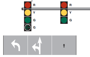 All GREEN heads terminate together. | TMUTCD Figure 4D-9 | |||
X | X | 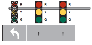 | TMUTCD Figure 4D-10 | |||
X | X | 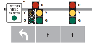 Sign is Optional 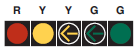 Horizontal Option | TMUTCD Figure 4D-11 | |||
X | X | 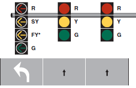 | TMUTCD Figure 4D-12 | |||
X | X | 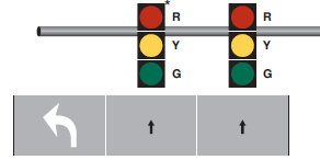 | TMUTCD Figure 4D-6 | |||
X | X | 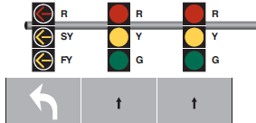 | TMUTCD Figure 4D-7 | |||
Engineering Study
An engineering study should be conducted to determine the
appropriate left-turn signal control mode for signalized intersections.
The study should consider left-turn volumes, crash history, 85th percentile
(posted) speed, sight distance, number of left-turn lanes, number
of opposing through lanes, pedestrian volumes, and opposing through
volumes. Additionally, intersection geometry can affect the selection
of the left-turn signal control mode. Intersections with wide medians, conflicting
turning paths, non-standard alignments, etc., are also factors in
determining left-turn signal mode.
There are many sources for determining left-turn control mode.
Two flow charts obtained from recent research projects that may
be used as an aid in determining the appropriate left-turn control mode
are shown below.
- Figure 62: “Decision-Making Flowchart for Selecting Left-Turn Signal Control Mode,” FHWA/TX-09/0-5840-1, , Authors: Lei Yu, Yi Qi, Hongxi Yu, Lei Guo and Xin Chen.
- Appendix A, Figure A-6. “Guidelines for Determining Left-Turn Operational Mode,” FHWA/TX-11/0-6402-P1, . Authors: J. Bonneson, S. Sunkari, M. Pratt, and P. Songchitruksa.
Recommended Practice
Flashing Yellow Arrow (FYA) is an option for protected-permissive
left-turn phasing. Careful consideration is needed in deciding where
to install the FYA.
Some areas have existing FYA installations, while others have
no experience with the display. Generally, implementation should
consist of an initial pilot or demonstration project consisting
of a few isolated intersections or a small section of corridor.
The district should obtain local buy-in and approval, and provide
press releases and information explaining where the FYA is being
installed, what the FYA indications mean, how the motorists should
interpret the indications, and why we are changing the existing
set-up (the benefits).
Locations to consider for the pilot project installation of
FYA protected-permissive left turns are typically sections of corridors
with signalized intersections with the following characteristics:
- Low speeds
- 1 left-turn bay per approach
- 3 or less through lanes
- Low number of left-turn related crashes
- Adequate driver sight distance to oncoming vehicles
- Low left-turn volume during peak periods
- Low traffic volume
- Signal coordination plans indicate operational improvement with the FYA protected-permissive operation.
Locations with the following characteristics are discouraged
for use in the pilot project installation of FYA protected-permissive
left turns:
- Corridors with multiple signalized intersections in view using solid green ball for permissive phase
- High speeds
- Dual left-turn lanes
- 4 or more through lanes
- High left-turn crash history
- Poor sight distance to oncoming vehicles
- High left-turn volumes during peak periods, and/or
- High traffic volumes.
It is better to be consistent in the application of left-turn
treatment along a corridor for driver expectation. That said, it
may not be practical to install FYA left turns consistently along
a corridor. FYA left-turn operation requires a separate left-turn
signal face. If a corridor is equipped with shared signal faces
it may need new signal poles installed with longer mast-arms to
cover the left-turn lane. Thus, it may be cost prohibitive to convert
to FYA left-turn operation.
Installing FYA protected-permissive mode at a location that
previously operated in protected-only mode should be considered
only after careful study of the intersection. One research study
of locations that were converted from protected-only mode to FYA
protected-permissive mode saw an increase in the crash frequency.
Do not remove protected-only left-turn phasing if opposing sight distance
is inadequate for permissive left turns, operating speed is too
great, roadway geometry is complicated, or there are too many opposing
through lanes. If the protected-only left turn was installed for
other safety reasons (crash prevention when under less restrictive
phasing), care should be used in operating a possible FYA protected-permissive
installation.
Emergency Preemption
Installing protected-permissive FYA operation along emergency
vehicle preemption routes requires special study and consideration.
Work closely with emergency vehicles to provide the preemption operation
that best fits their preference. Carefully consider whether to allow
or terminate FYA for the opposing left during preemption. If the
opposing FYA is to be turned off during preemption, the through
phases will need to be terminated (go to all red) prior to dropping
FYA for preemption.
For example, consider an intersection that is displaying Circular
GREEN (for through) and FYA (left-turn lane) for both approaches
of an arterial. Then, preemption activates to provide a protected through
and left turn (Circular GREEN and GREEN ARROW dwell phase) to the
approach for the emergency vehicle. From here, there are two possible
states for the opposing left-turn FYA. It may continue to flash
during the preemption dwell phase or it may be terminated. If it
is decided to terminate the opposing left-turn FYA, then to go to
all-red prior to displaying the dwell phase.
Variable Mode Operation
Variable mode operation is when signal operation changes between
protected-only to protected-permissive mode, or between protected-permissive
to permissive-only operation based on the time of day. It is possible
with the 4-section FYA signal face when a study shows this type
of operation to be beneficial. However, you must ensure that the
controller is capable of switching between modes such that the flashing
yellow arrow indication and the opposing through movement indication
terminate together.
In other words, the controller should be capable of transitioning
between modes without the flashing yellow arrow terminating while
the opposing through movement stays green. Additionally, when switching
between protected-permissive to permissive-only mode, ensure that
the controller is capable of reassigning the left-turn detectors
to call the associated through phases by time of day.
Public Notification
Installation of FYA left-turn operation should be coordinated
with the District Public Information Office. Consider press releases
with specific details on when the public can expect to see the new indications.
Press releases should be prepared and sent out approximately two
weeks or more in advance of conversion. Special attention should
be given to the first installation in an area. If available, place
portable changeable message signs in advance of the affected signals
at least five days before the FYA activation date.
Equipment Issues
The majority of current TxDOT traffic signal equipment is
compatible with FYA operation. TxDOT signal cabinets, as currently
equipped, can be modified to perform FYA. Prior to installing or
converting an intersection to FYA left-turn operations, it will
be necessary to ensure that there is adequate field wiring, the
signal controller cabinet has adequate channels (load switches),
and the controller and Malfunction Management Unit (MMU) are capable
of FYA operation. Configuration of the traffic signal cabinet may
be dependent on several conditions at the intersection such as the controller
requirements, the monitor requirements, the cabinet size and available
load switches, and whether pedestrian signals are being utilized.
Careful planning is required to ensure a successful installation.
Cabinet Modification
Controller manufacturers have standardized FYA operation,
however, there may be older equipment that is not FYA compatible.
Cabinet modification will depend on controller make and model. An
MMU capable of FYA operation is required. If needed, install a new
MMU recommended by the controller manufacturer. A modification to
the cabinet flash programming is required. Contact the manufacturer
representative or the TRF-TM Engineering Support Branch for assistance
if needed.
Signing
While the 2011
TMUTCD
does not
require this signing, a "Left-Turn Signal - Yield on Flashing Arrow"
(R10-17T) sign should be installed adjacent to the new head for
clarification. If the FYA face is to be installed at an existing
location with a 5-section face, verify the sign can be installed and
ensure any conflicting signs, such as the "Left Turn Yield on Green”
sign (R10-12), is removed if in place.Observations
Signal observations should be performed periodically as discretely
as possible, and particularly during the times where the phasing
has changed from the previous installation. When converting left-turn
signal operations to FYA protected-permissive, be sure to observe
driver behavior, especially in cases where the intersection previously
operated in a protected-only mode.
Crash Data
With the initial FYA installations in your area, monitor the
crash data for at least one year after installation.
Other Considerations
The 2011
TMUTCD
provides Figure 4D-3, "Recommended Vehicular Signal Faces for Approaches with Posted, Statutory, or 85th Percentile Speed of 45 mph or Higher," and Table 4D-1, “Recommended Minimum Number of Primary Signal Faces for Through Traffic on Approaches with Posted, Statutory, or 85th-Percentile Speed of 45 mph or Higher” (Shown in Figures 5-2 and 5-3 below). Requirements from the table are a "should condition," The table should be consulted for minimum number and location of primary signal faces for through traffic.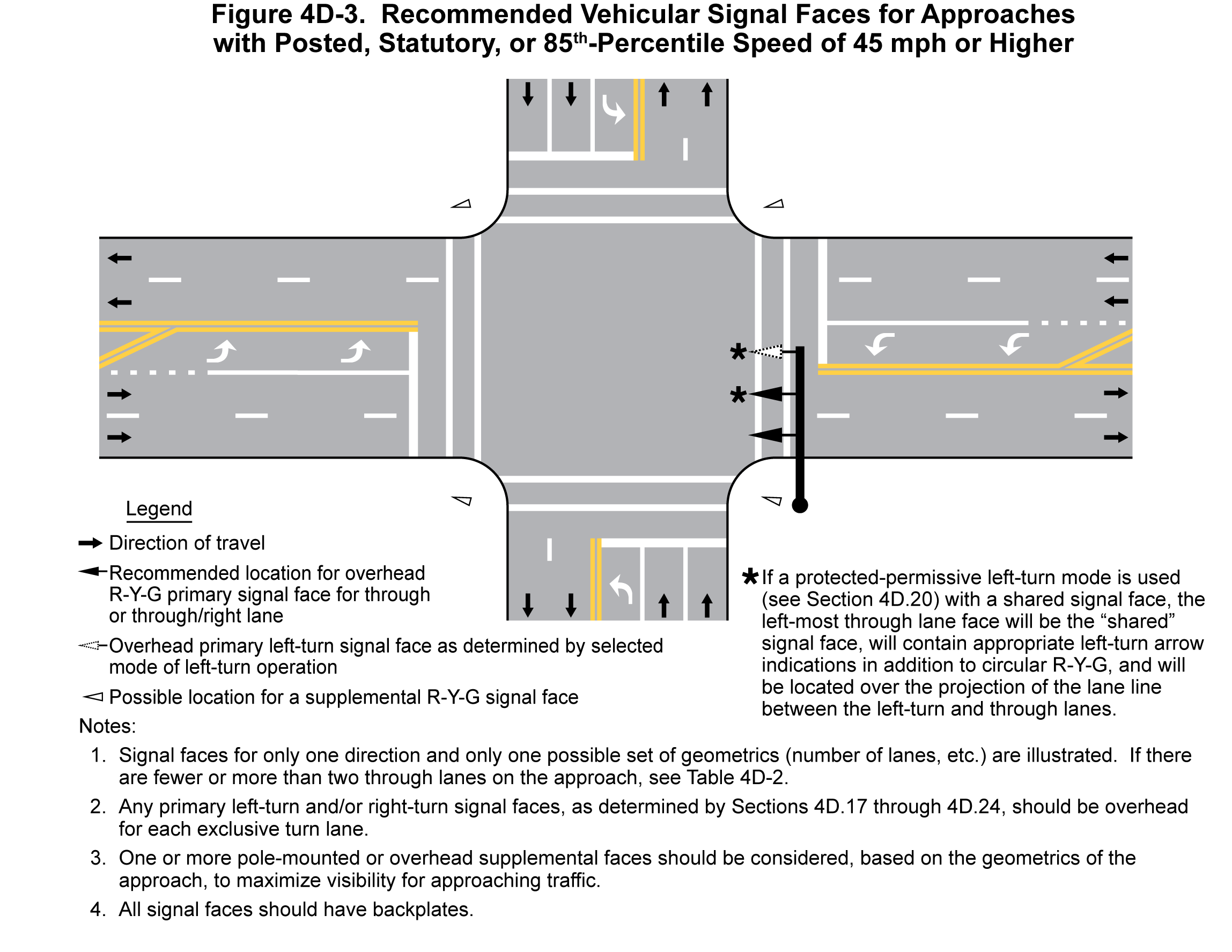
Figure 5-2. TMUTCD Figure 4D-3: “Recommended Vehicular Signal Faces for Approaches with Posted, Statutory, or 85th Percentile Speed of 45 mph or Higher”
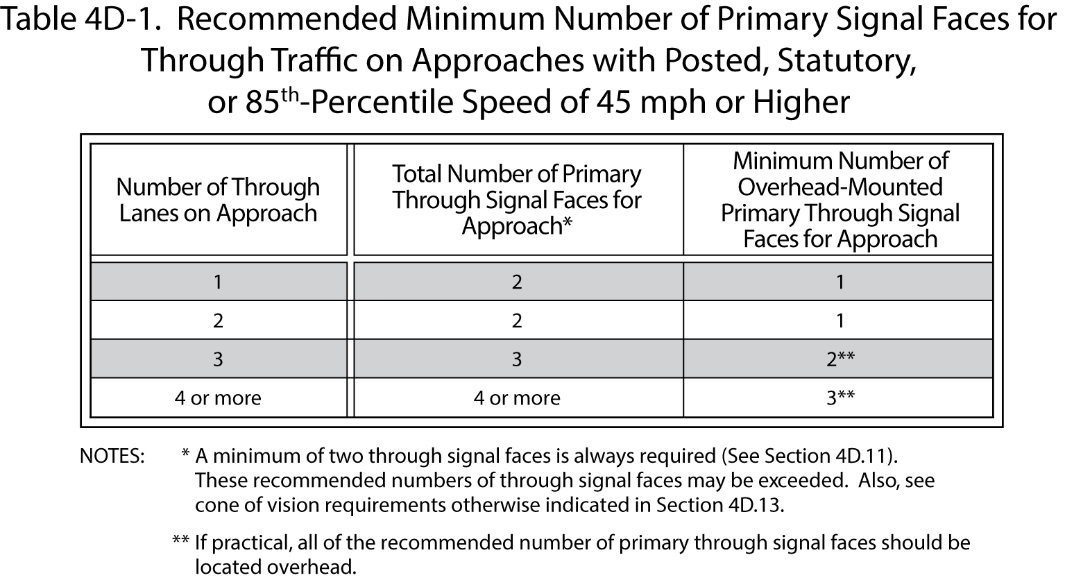
Figure 5-3. TMUTCD Table 4D-1. “Recommended Minimum Number of Primary Signal Faces for Through Traffic on Approaches with Posted, Statutory, or 85th-Percentile Speed of 45 mph or Higher”
References
- David A. Noyce, Casey R. Bergh, Jeremy R. Chapman, NCHRP Web Only Document, 123,Evaluation of the Flashing Yellow Arrow Permissive-Only Left-Turn Indication Field Implementation.
- Yi Qi, Xiaoming Chen, Lei Yu, Yubian Wang, Min Zhang, Peina Yuan and Khali R. Persad, FHWA/TX-09/0-6568-1, .
- 2011 (TMUTCD).