Section 3: Arrangement of Components
Introduction (Texas MUTCD, Section 2D.29)
Conventional guide sign assemblies are created by combining
the various components described in the previous section. These
components are used in a particular manner and arrangement to ensure uniformity
for the driver. This section concentrates on illustrating how guide
signs, particularly route signs, are to be arranged in different
assemblies so that different classes of highways and/or directions
of travel are consistent.
The following terminology is used in describing the arrangement
of guide sign components:
- Component:The individual signs that are attached to a post or sign.
- Unit:A collection of components that present the information related to travel on a specific highway. A unit consists of a route sign and the auxiliary signs (if used) above and below the route sign. The typical unit consists of (from top to bottom): a cardinal direction sign, a route sign, and a directional arrow sign.
- Assembly:A collection of units that present information related to travel on all highways at or near a specific intersection.
Guide Sign Units
The first step in arranging guide sign components is to identify
the individual units that must be presented at a given location.
This is accomplished by identifying the route signs applicable to
a given location and selecting the signs that should be used above
and below the route sign. Signs with the same information (such
as the same cardinal direction or arrow) should also be identified so
that they might be combined within the assembly. Table 3-2 identifies
the components that can be used in the upper and lower positions
of a unit. Figure 3-15 provides examples of guide sign units.
Arrangement Hierarchy
Once the units have been identified, hierarchal relationships are used to determine the position of the units within the assembly. The following steps are used to determine placement:
- Select arrangement pattern: horizontal, vertical, or combination of both.
- Identify units by direction.
- Identify highway class within a given direction.
- Identify highway number within a given class.
Position | Possible Components |
|---|---|
Upper | Cardinal Direction, Junction, Business, To, Alternate, End, Truck, By-Pass, Temporary, Begin |
Middle | Route Sign |
Lower | Directional Arrow, Advance Turn Arrow, Lane Use |
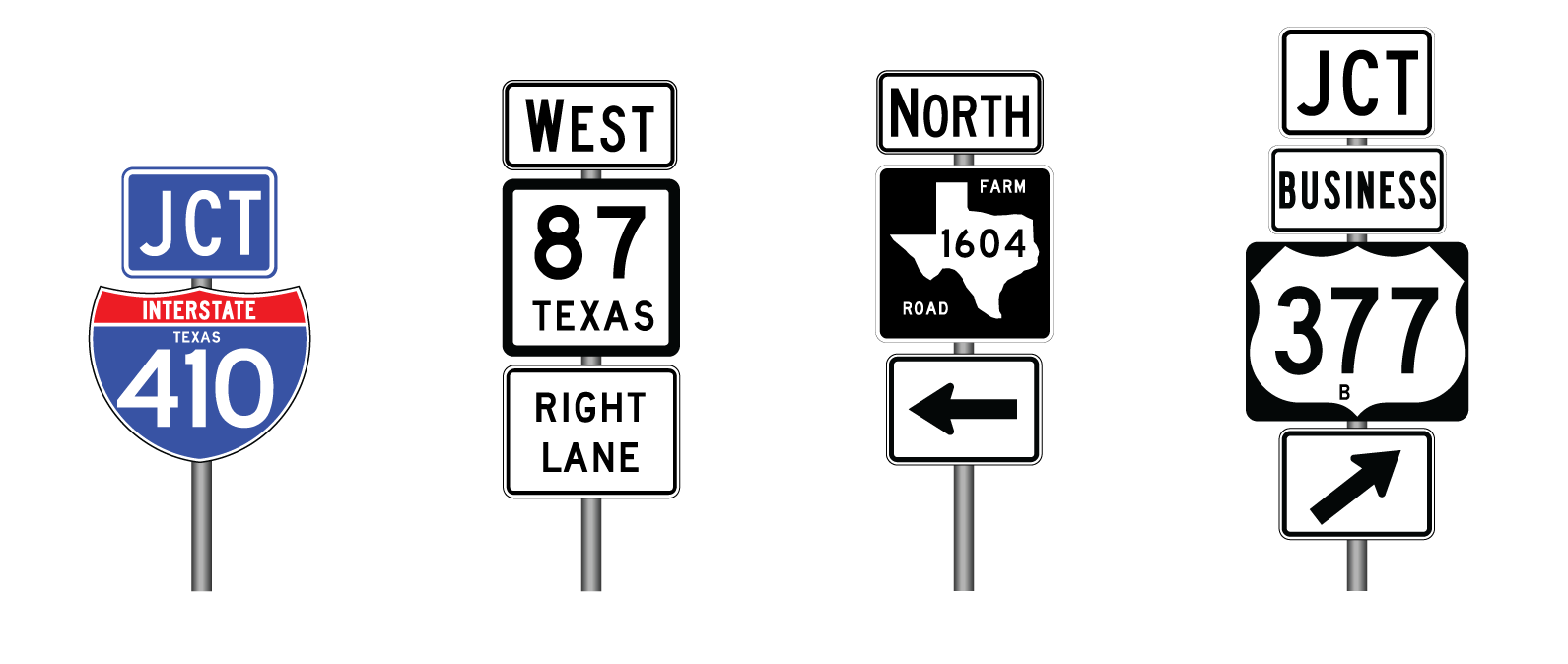
Figure 3-15. Examples of a Guide Sign Unit
Arrangement Pattern
Guide sign units may be arranged so that all units are side-by-side (horizontal), top-to-bottom (vertical), or a combination of both. Figure 3-16 illustrates some of the combinations of arrangements that can be found when up to three units are displayed in an assembly.
- Horizontal Arrangement -In a horizontal arrangement, all units are side-by-side. The horizontal arrangement is the best arrangement from a driver information standpoint, as the units are arranged in a manner that relates to the directions that a driver must turn (that is, a unit requiring a left turn is on the left side). Figure 3-17 provides examples of horizontal guide sign unit arrangements.
- Vertical Arrangement -In a vertical arrangement, all units are top-to-bottom. Vertical arrangements may be used when the available width for an assembly is restricted. When units are arranged vertically, additional space should be provided between units to help the driver distinguish between directions (see Layout Dimensions for Assemblies, page 3-27). For route signs of the same color, directional arrows and cardinal direction plaques are omitted when redundant. For example, if a left turn heads in the same cardinal direction for 2 highways, only 1 cardinal direction and 1 directional arrow are needed for the 2 route signs. Figure 3-18 provides examples of vertical guide sign unit arrangements.
- Combination of Horizontal and Vertical Arrangements -When there are three or more units, the assembly may be arranged in a manner that includes both side-by-side and top-to-bottom arrangements. To the extent possible, units should be arranged horizontally by direction. Units that share a common direction should be arranged vertically. In some cases, it may be necessary to include multiple directions in a single vertical stack. Figure 3-19 illustrates different possibilities for combination arrangements involving 3 or 4 units.
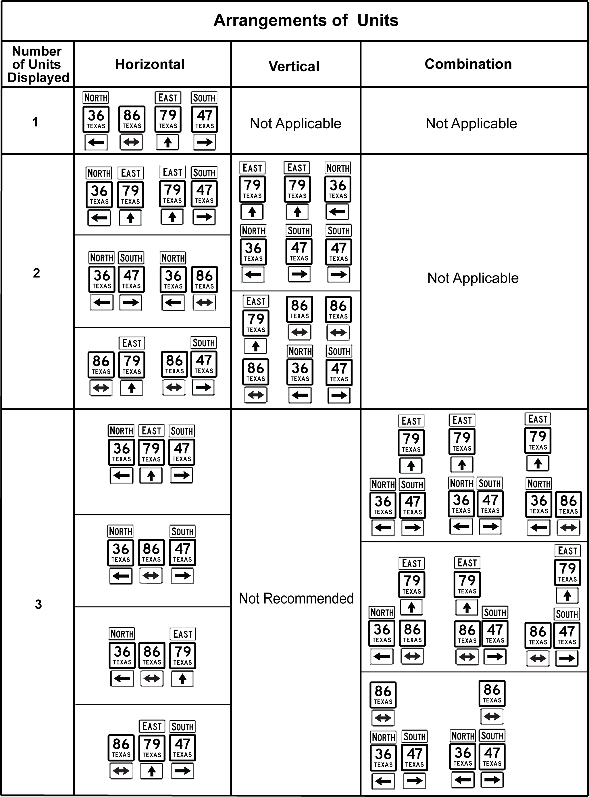
Figure 3-16. Arrangements of Guide Sign Units
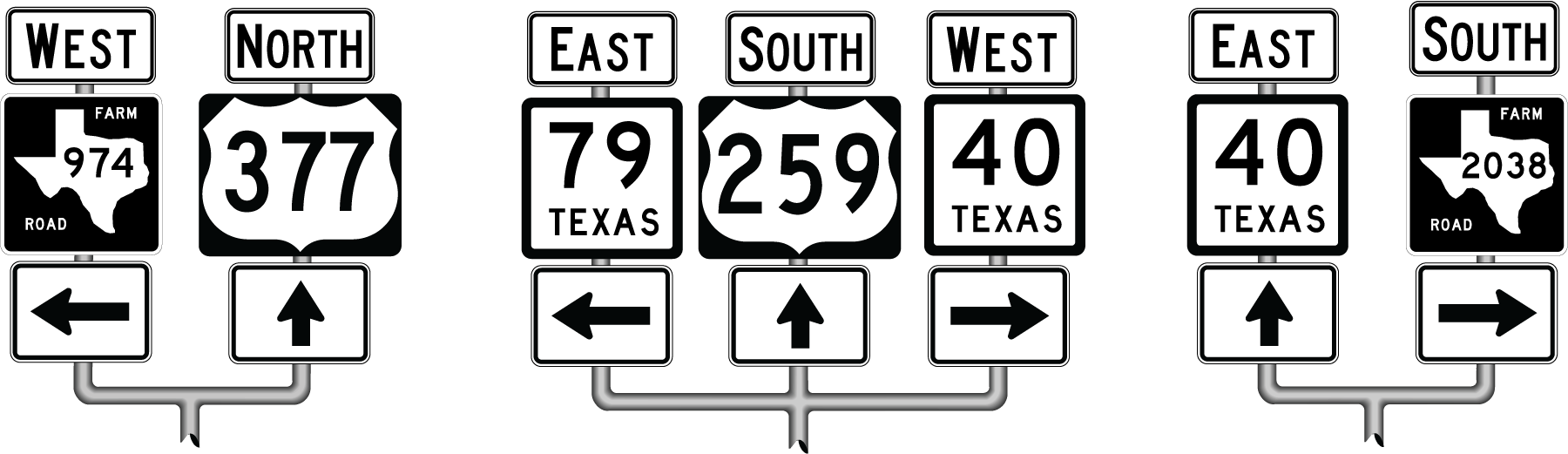
Figure 3-17. Horizontal Arrangement
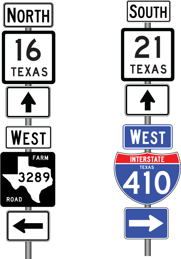
Figure 3-18. Vertical Arrangement
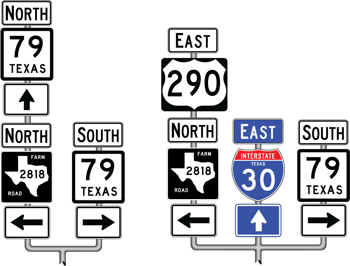
Figure 3-19. Combination Arrangement
Arrangement by Direction
The initial grouping of units is by direction. This requirement
applies regardless of class of highway or route number. Highway
routes with a common direction may be combined with a single directional
arrow sign.
- Directional Hierarchy for Horizontal Arrangement (left to right): Left, Double Arrow, Through, Right.
- Directional Hierarchy for Vertical Arrangement (top to bottom): Through, Double Arrow, Left, Right.
Arrangement by Class of Highway
Within a given direction, route signs are arranged by highway
classification. The higher class highway should be at the top or
left. The following list indicates the hierarchy of highway classes,
from the highest to the lowest.
- Interstate and Toll Interstate
- U.S. Highway and Toll U.S. Highway
- U.S. Highway Alternate
- U.S. Highway Spur
- OSR, NASA, State Highway, and Toll State Highway
- State Highway Alternate
- Loop, Beltway, or Spur
- Business Interstate Loop or Business Interstate Spur
- U.S. Highway Business
- State Highway Business or Farm (or Ranch) to Market Road Business
- Farm to Market Road or Ranch to Market Road
- Ranch Road
- Park Road
- Recreational Road
- Recreational Road Spur
- Farm to Market Road Spur or Ranch to Market Road Spur
- Ranch Road Spur.
Arrangement by Highway Number
Within a direction and highway class, route signs are arranged
by number. Lower numbers should be at the top or left.
Examples of Assembly Arrangements
Figures 3-20, 3-21, and 3-22 illustrate arrangements of route sign assemblies for intersections with 2, 3, and 4 route signs, respectively. When an Option A or Option B is presented in the figures, Option A is the correct arrangement to be used provided all of the conditions under 'Double Arrow Sign' are met (see page 3-12). Option A will require fewer route marker signs. When arranging route marker assemblies, the arrangement hierarchy is always determined first by direction, then highway class, and then highway number as described above under 'Arrangement Hierarchy' (see page 3-17). Horizontal arrangements are preferred if sufficient right-of-way width is available.
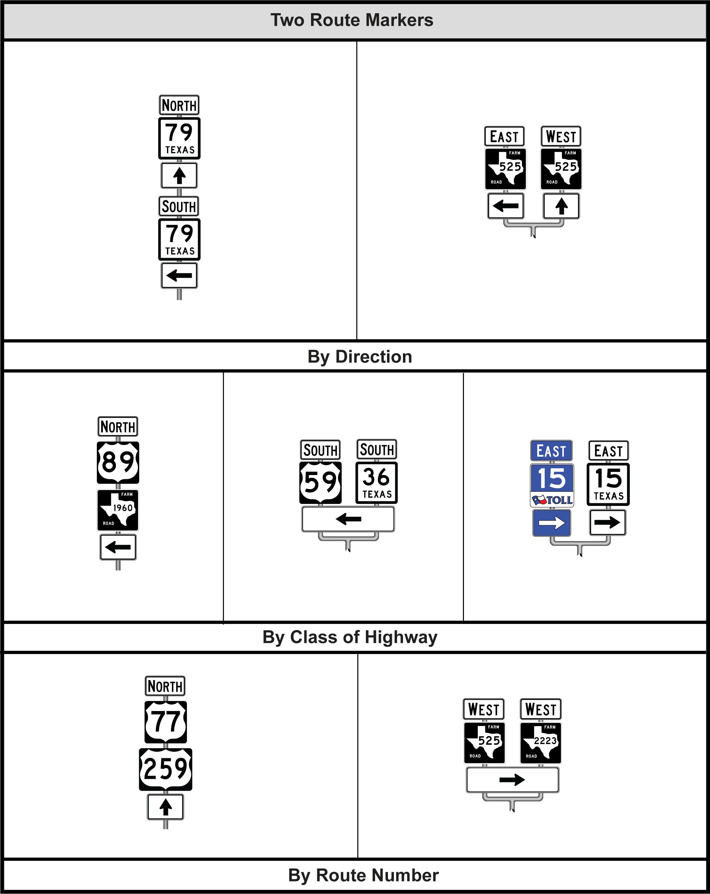
Figure 3-20. Route Sign Assembly for Intersection with Two Route Signs
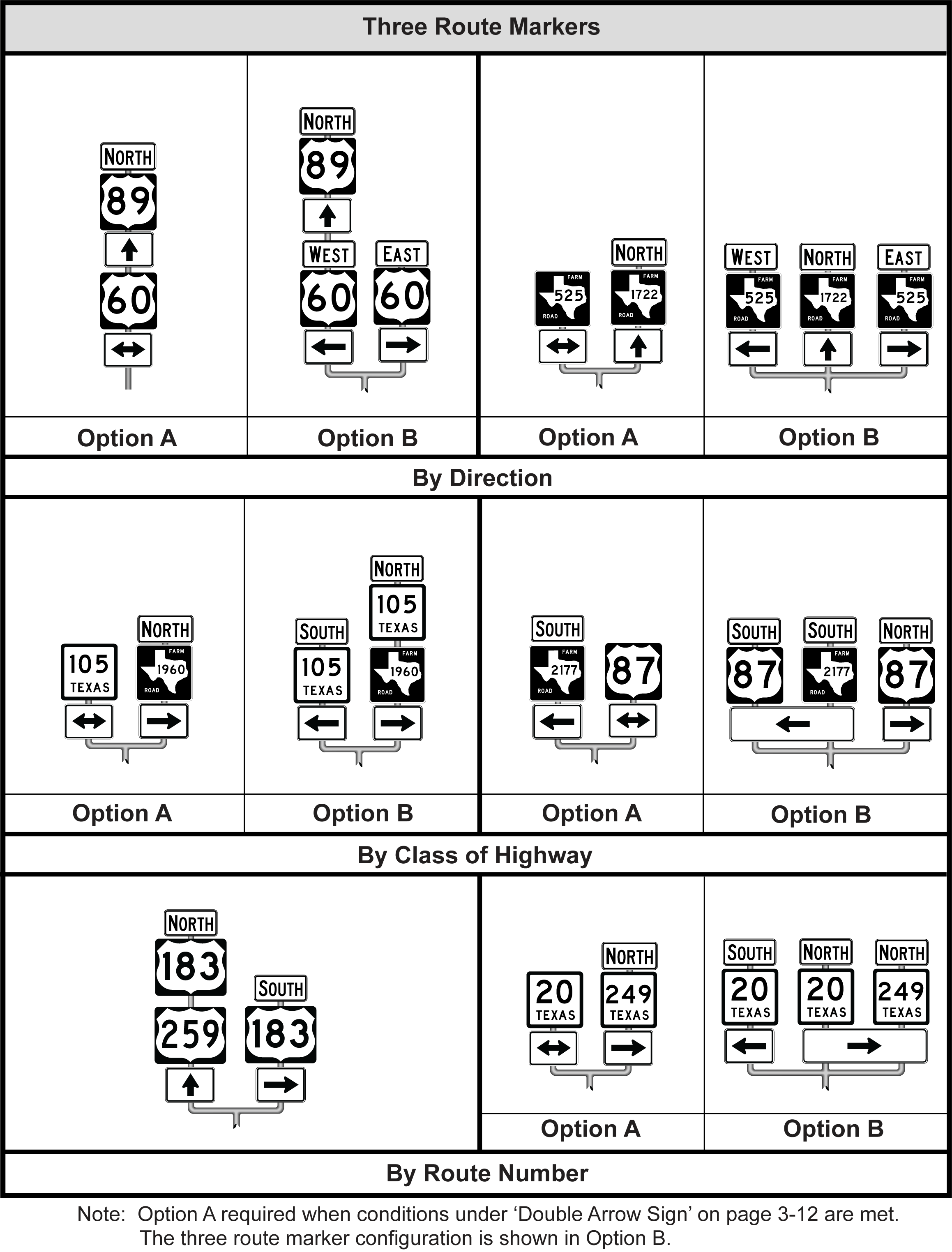
Figure 3-21. Route Sign Assembly for Intersection with Three Route Signs
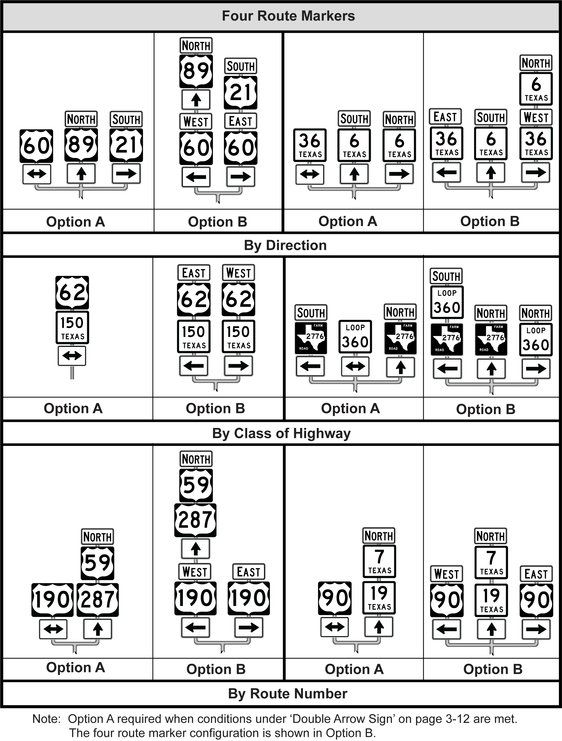
Figure 3-22. Route Sign Assembly for Intersection with Four Route Signs
Layout Dimensions for Assemblies
The following dimensions should be used for the layout of the individual components and units in an assembly. These dimensions are illustrated in Figure 3-23.
- The space between the individual components of a unit should be approximately 1 inch.
- There should be approximately 4 inches between individual units arranged vertically in an assembly.
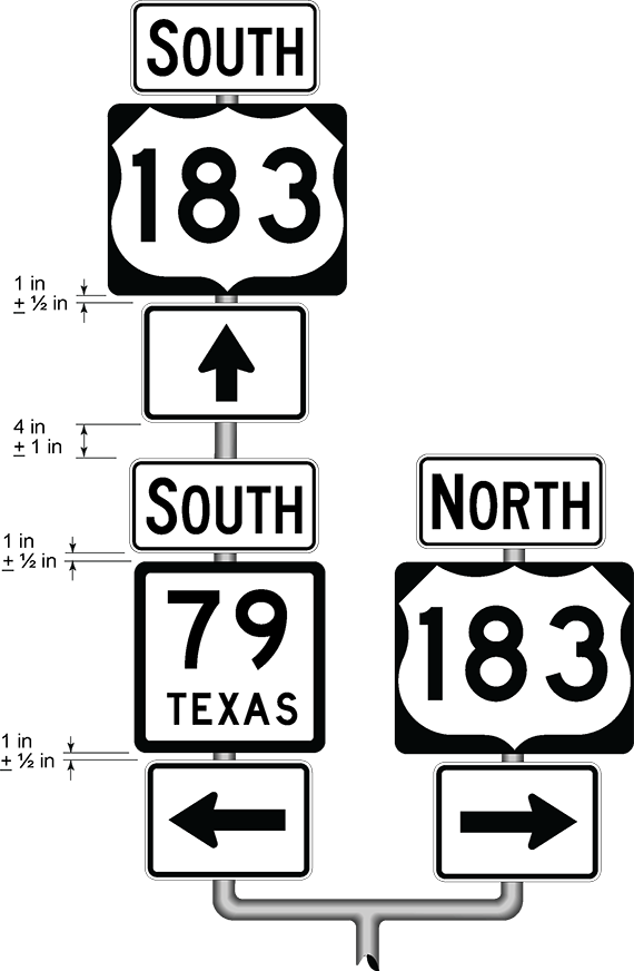
Figure 3-23. Layout Dimensions for Assemblies