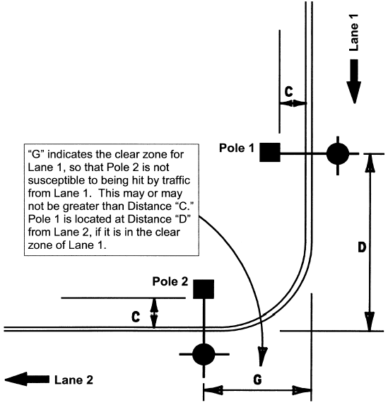
Breakaway Pole Placement Examples
Figure 6-7 and Figure 6-8 show examples of breakaway pole placement and respective minimum applicable distances recommended for each of the cases listed in the following tables.
Case No. | Case | Shown in |
|---|---|---|
1. | Median-mounted poles or poles inside the clear zone of two separate roadways. | Figure 6-7 |
2. | Outside clear zone of frontage road, but inside the clear zone of main lanes. | Figure 6-7 |
3. | Outside clear zone of main lane, but inside clear zone of frontage road. | Figure 6-7 |
4. | Minimum distance from ramp. | Figure 6-7 |
5. | House side of frontage road. | Figure 6-7 |
6. | Minimum distance from overhead electric lines (OHE). | Figure 6-7 |
7. | City street intersection. | Figure 6-8 |

Figure 6-7. Controlled access facility illustrating example Cases 1 through 6. Minimum distances (designated here by the letters A through G) are shown in the table below.
(Indicated by Letter in this table and in Figure 6‑8) | ||||
|---|---|---|---|---|
A. | 2/5 (40%) of one mounting height from edge of travel lane. | |||
B. | 15 feet from edge of travel lane (20 feet desirable). | |||
C. | Depends on whether or not the roadway is curbed or uncurbed and on the design speed (see following table). | |||
Pole Offset from Roadway | ||||
Distance from Curb Face or Lane Edge | ||||
Lane Edge | Design Speed | Desirable | Minimum | |
Barrier Curb* | 45 mph or lower | 10 ft. | 2.5 ft.** | |
Barrier Curb* | 50 mph or higher | 20 ft. | 15 ft.** | |
Uncurbed | 40 mph or lower | 15 ft. | 10 ft.** | |
Uncurbed | 45 mph or higher | 20 ft. | 15 ft.** | |
* Curbed roadway denotes a roadway with a 6-inch minimum barrier-type curb. All mountable-type curb is considered as uncurbed. ** or as near ROW line as practicable. | ||||
D. | One mounting height. | |||
E. | 20 feet, or as required by utility company. | |||
F. | 8 feet, or as required by utility company. | |||
G. | Clear zone. | |||

Figure 6-8. Example Case 7. Minimum distances (designated by letters) are shown in the preceding table.