Section 4: Railroad Preemption Operation Specification
The purpose of this standard is to define the required operations for the purpose of railroad preemption.
Traffic Signal Operation
At interconnected traffic signals, the controller assembly, consisting of the traffic signal controller and cabinet, shall provide the operation detailed below relative to the preemption functionality and operation.
The controller assembly shall be provided with all hardware, software and firmware necessary to provide the operation described herein. The designer, contractor and/or traffic signal technician should closely review the functional requirements of the railroad preemption operation to assure that the equipment is capable of performing the functions as specified. In many cases, the railroad circuits have been designed to provide and support the specific functionality. As a result, no exceptions will be permitted to these requirements.
Interconnection Circuits
The following sections expand upon the railroad relays/circuits discussed in Chapter 4 and specify how these circuits shall interact with the traffic signal system. The combined circuits are specified in the preemption design and are referred to as the “Interconnection.” The designer shall request the circuits from the railroad to meet the needs of the specific grade crossing location as determined by the diagnostic team.
Advance Pedestrian Preemption (APP)
The Advance Pedestrian Preemption (APP) circuit may be included to extend the Total Approach Time (TAT) beyond what is allowed by the AREMA 50 second rule and provide pedestrian clearance. When an APP circuit is specified, it should always be in conjunction with an Advance Vehicle Preemption (AVP) circuit.
The railroad may provide this circuit to notify the traffic signal controller of an approaching train prior to AVP and prior to activation of the railroad warning devices. The time interval between this notification and the instant when the AVP circuit is activated is known as the Advance Pedestrian Preemption Time (APPT). The Advance Pedestrian Preemption (APP) circuit should be single break.
When the APP circuit is activated, the following sequence shall occur:
- Any pedestrian walk interval which has not completed its programmed value should be truncated to zero. The signal controller should immediately begin the pedestrian change interval.
- Any pedestrian change interval which has not completed its programmed value may be truncated to an alternate pedestrian change value.
- When the pedestrian change interval has completed timing, no new pedestrian service shall begin until this circuit returns to its non-activated state. If no pedestrian service is active when the APP circuit is activated, no new pedestrian service shall be allowed. Any pedestrian calls received during APP shall be stored until pedestrian service is allowed. During the APPT interval, vehicular movements shall continue to operate normally.
Advance Vehicle Preemption (AVP)
The AVP circuit is only used when APP operation is specified. This circuit notifies the traffic signal controller of an approaching train prior to activation of railroad warning devices. The period of time between this notification and the instant when the railroad warning devices are activated is known as Advance Vehicle Preemption Time (AVPT). In most cases, AVPT should be used by the traffic signal controller to terminate any active non-track clearance vehicular movements and to transition to a programmed track clearance interval to clear the track(s). The AVP circuit should be single break.
When this input is activated, the following sequence shall occur:
- Any minimum green interval which has not completed its programmed value shall be truncated to an alternate minimum green value (usually zero).
- The normal yellow change interval shall complete its programmed value. The yellow change interval shall begin once the pedestrian intervals and the minimum green interval have completed their timing.
- The normal red clearance interval shall complete its programmed value.
- The Preemption Clearance Interval shall start immediately following completion of the red clearance interval and shall continue until the gate down input is received and the minimum Preemption Clearance Interval has been served.
Advance Preemption (AP)
This circuit is used when APP operation is NOT specified. Where used, the railroad may provide this circuit to notify the traffic signal controller of an approaching train prior to activation of the railroad active warning devices. The period of time between this notification and the instant when the railroad warning devices are activated is known as Advance Preemption Time (APT). In most cases, APT is used by the traffic signal controller to terminate any active non-track clearance movements and to change to a programmed Preemption Clearance Interval to clear the track(s). The Advance Preemption circuit should be single break with supervision.
When this input is activated, the following sequence shall occur:
- Any pedestrian walk interval which has not completed its programmed value may be truncated to an alternate walk value and any remaining walk time shall be completed. When the alternate walk time has completed, the associated pedestrian change interval shall begin.
- Any pedestrian change interval which has not completed its programmed value may be truncated to an alternate pedestrian change value.
- Any minimum green interval which has not completed its programmed value shall be truncated to an alternate minimum green value.
- The normal yellow change interval shall complete its programmed value. The yellow change interval shall begin once the pedestrian intervals and the minimum green interval have completed their timing.
- The normal red clearance interval shall complete its programmed value.
- The Preemption Clearance Interval shall start immediately following completion of the red clearance interval and shall continue until the gate down input is received and the minimum Preemption Clearance Interval has been served.
Supervision (SUPR)
The supervision circuit is provided through a railroad relay back contact and monitored by the railroad interface for a fault condition in the interconnection cable. The supervision circuit is the inverse operation of the circuit being supervised. If the circuits are both energized or are both de-energized at any time, this shall indicate a vital interconnect failure and shall cause the traffic signal controller unit to transition to all-red soft flash until the fault is repaired. When the Advance Preemption circuit is specified, it should be the supervised circuit; otherwise, the Crossing Active (XR) circuit should be the supervised circuit.
Crossing Active (XR)
The railroad may provide this circuit to notify the traffic signal controller of an approaching train at the same time the railroad warning devices activate. This circuit is commonly referred to as an "XR" circuit by the railroad. It is also the circuit typically used for “Simultaneous Preemption”. The XR or equivalent circuit should be single break. The XR circuit shall be connected in such a way that the Simultaneous Preemption Relay can never be down with the XR relay up. This is commonly circuited by having the XR relay as a repeater of the preemption relay.
Where Advance Preemption is used, the traffic signal controller should enter the preemption sequence during the APPT, AVPT and/or APT period for through train moves. However, where a train restarts within the approach circuit to the crossing, the APT may be reduced or eliminated. This commonly occurs where railroad switching operations take place, where trains meet or pass, or where trains stop at stations within the approach circuit to the crossing. The railroad then has operating rules which govern the movement of trains over the crossing. However, in these instances where APT is reduced or eliminated and the Crossing Active input is activated, any remaining walk, pedestrian change or minimum green time shall be truncated to zero. Yellow change shall begin for any phases other than the Preemption Clearance Interval phases followed by the red clearance interval. The Preemption Clearance Interval shall start immediately following completion of the red clearance interval and shall continue until the gate down input is received and the minimum Preemption Clearance Interval has been served. The crossing active circuit should also be used to activate blank-out signs restricting movement towards the crossing during preemption.
At locations without gates, this circuit should be used to terminate the Preemption Clearance Interval. Once the crossing active circuit is energized, the traffic signal has at least 20 seconds to complete the Preemption Clearance Interval and transition to limited service. If the advance preemption circuit has already energized, the signal should already be transitioning to the Preemption Clearance Interval. The Preemption Clearance Interval should extend beyond receipt of the crossing active input until the minimum Preemption Clearance Interval has been served.
Where Simultaneous Preemption is used, the traffic signal controller shall transition to the Preemption Clearance Interval as soon as possible. The following sequence shall occur:
- Any pedestrian walk interval which has not completed its programmed value should be truncated to zero.
- Any pedestrian change interval which has not completed its programmed value should be truncated to zero.
- Any minimum green interval which has not completed its programmed value should be truncated to zero.
- The normal yellow change interval shall complete its programmed value.
- The normal red clearance interval shall complete its programmed value.
- The Preemption Clearance Interval shall start immediately following completion of the red clearance interval and shall continue until the gate down input is received and the minimum Preemption Clearance Interval has been served.
Gate Down (GD)
If gates are present at the grade crossing, the railroad may provide this circuit to notify the traffic signal controller when the gate(s) controlling access over the track(s) approaching the intersection is/are almost horizontal. The traffic signal controller unit shall not leave the Preemption Clearance Interval until the gate down circuit is closed indicating that the gate(s) is/are down confirming that vehicles are physically restricted from entering the crossing area. Once the gates are down the traffic signal must finish clearing vehicles that have already entered the crossing area.. The traffic signal controller shall extend the Preemption Clearance Interval until the gate down input is activated.
The Gate Down circuit should be single break. If more than one gate controls access over the crossing approaching the intersection or if exit gates are present at the grade crossing, then all mechanisms must indicate that they are lowered prior to closing the Gate Down relay. All gates on approach to an interconnected traffic signal should be connected to the Gate Down circuit to provide the appropriate Gate Down information. In accordance with AREMA 16.30.10, the Gate Down shall be wrapped by the Island relay. This will provide a fail-safe Gate Down indication to the traffic signal controller in the event one or more of the included gates is not down and the train occupies the Island circuit.
Island Occupied (ISLD)
This circuit may be provided by the railroad if requested and will notify the traffic signal controller when a train has physically entered the limits of the grade crossing. This is referred to as the “Island”. This circuit may be used to terminate the Preemption Clearance Interval in the absence of a gate down indication as noted in the discussion of the Gate Down circuit. However, by the time the island circuit is energized, the train is already at the crossing. Consequently, a separate island circuit is only applicable in unique situations at locations where there are no gates present. The Island relay circuit should be single break.
Traffic Signal Health Circuit (TSH)
The traffic signal controller shall notify the railroad warning system whenever the traffic signal has entered conflict flash, manual flash, soft flash, manual signals off, or when commercial power and backup power system has failed (signals off) through a traffic signal health circuit. The railroad may, at their option provide a traffic signal health relay which will normally be energized by this input. Whenever the Traffic Signal Health relay is down, the operation of the railroad warning devices shall be extended by the Advance Preemption (and APP, if used) time. The Traffic Signal Health relay must remain open until the XR relay closes.
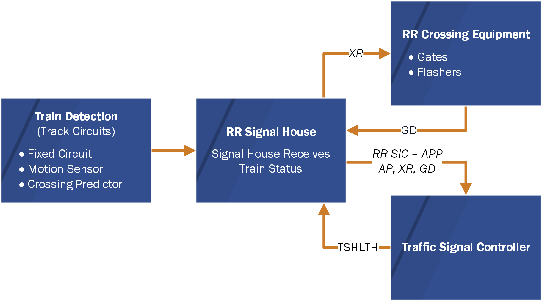
Figure 5–2. Crossing Circuit Diagram
Functional Implementation
The preemption sequencing shall be implemented through the railroad preemption system installed in the cabinet assembly. Based on the states of the interconnection inputs from the railroad warning system, the system will call pre-defined preemption plans in the controller unit as shown in Figure 5-3. Note, this is according to the static configuration where each preemptor is assigned to a specific railroad circuit.
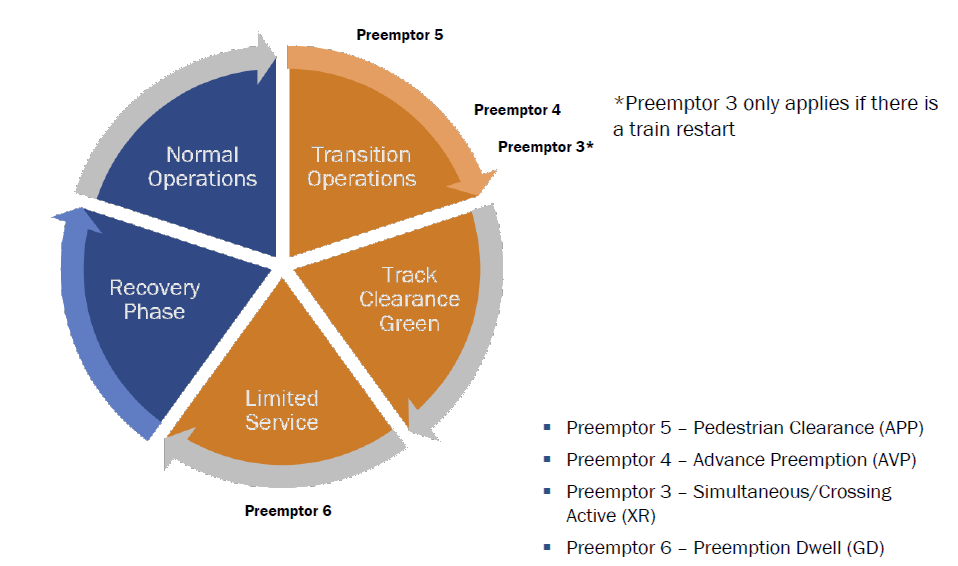
Figure 5–3. Preemptors Used in a Static Configuration
Each preemption plan must be configured for non-locking operation providing the operation described in the following statements:
Preemptor 1 – All-Red Soft Flash
When activated, this plan has priority over all other preemption plans. The controller unit shall transition to All-Red Soft Flash via the following steps:
- A preemption delay period shall elapse prior to transition to this plan. This delay period is typically set to allow a railroad preemption system module to be changed within a short period of time without placing the intersection into flashing operation.
- Any pedestrian walk interval which has not completed its programmed value shall be truncated to an alternate walk value and any remaining walk time shall be completed. When the alternate walk time has completed, the associated pedestrian change interval shall begin.
- Any pedestrian change interval which has not completed its programmed value shall be truncated to an alternate pedestrian change value.
- Any minimum green interval which has not completed its programmed value shall be truncated to an alternate minimum green value.
- The normal yellow change interval shall complete its programmed value.
- The normal red clearance interval shall complete its programmed value.
- The Preemption Clearance Interval shall start immediately following completion of the red clearance interval and shall continue until the minimum Preemption Clearance Interval has been served.
- The All-Red Flash interval shall be displayed and begin to time its programmed minimum time. Once the programmed time has completed, the sequence shall remain in All-Red Soft Flash operation until the Plan 1 input is no longer active.
- When the Plan 1 input is no longer active, the sequence shall advance to the programmed exit phases following a programmable steady All-Red display.
Preemptor 2 – Special Applications Interval
- Plan 2 is typically used where two Preemption Clearance Intervals are required based on site specific intersection geometry.
Preemptor 3 – Simultaneous/Crossing Active Interval
When activated, this plan has priority over lower numbered preemption plans. The controller unit shall transition to the Preemption Clearance Interval via the following steps:
- Any pedestrian walk interval which has not completed its programmed value shall be truncated to zero.
- Any pedestrian change interval which has not completed its programmed value shall be truncated to zero.
- Any minimum green interval which has not completed its programmed value shall be truncated to zero.
- The normal yellow interval shall complete its programmed value.
- The normal red clearance interval shall complete its programmed value.
- The Preemption Clearance Interval shall be displayed and begin to time its programmed minimum time. Once the programmed time has completed, the sequence shall remain in the Preemption Clearance Interval.
- When the Plan 3 input is no longer active, the sequence shall advance to the programmed exit phases.
Preemptor 4 – Advance Preemption Interval
When activated, this plan has priority over lower numbered preemption plans. The controller unit shall transition to the Preemption Clearance Interval via the following steps:
- Any pedestrian walk interval which has not completed its programmed value shall be truncated to an alternate walk value, and any remaining walk time shall be completed. When the alternate walk time has completed, the associated pedestrian change interval shall begin.
- Any pedestrian change interval which has not completed its programmed value shall be truncated to an alternate pedestrian change value.
- Any minimum green interval which has not completed its programmed value shall be truncated to an alternate minimum green value.
- The normal yellow change interval shall complete its programmed value.
- The normal red clearance interval shall complete its programmed value.
- The Preemption Clearance Interval shall be displayed and begin to time its programmed minimum time. Once the programmed time has completed, the sequence shall remain in the Preemption Clearance Interval.
- When the Plan 4 input is no longer active, the sequence shall advance to the programmed exit phases.
Preemptor 5 – Pedestrian Clearance Interval
When activated, this plan has priority over lower numbered preemption plans. The controller unit shall transition to the pedestrian change interval via the following steps:
- Any pedestrian walk interval which has not completed its programmed value shall be truncated to an alternate walk value and any remaining walk time shall be completed. When the alternate walk time has completed, the associated pedestrian change interval shall begin.
- Any pedestrian change interval which has not completed its programmed value shall be truncated to an alternate pedestrian change value.
- As long as the Plan 5 input is active, all allowed vehicle phases shall continue to operate normally. No new pedestrian service may begin.
- When the Plan 5 input is no longer active, the sequence shall advance to the programmed exit phases.
Preemptor 6 – Preemption Dwell Interval
When activated, this plan has priority over lower numbered preemption plans. The controller unit shall transition to the Preemption Dwell Interval via the following steps:
- The normal yellow change interval shall complete its programmed value.
- The normal red clearance interval shall complete its programmed value.
- The Preemption Dwell operation shall commence operation and remain as long as the Plan 6 input is active.
- When the Plan 6 input is no longer active, the sequence shall advance to the programmed exit phases.