Railroad Preemption Cable
Cable Materials
A railroad preemption cable must be a 15-conductor cable having a polyethylene jacket. The cable jacket must be rated for 600 Vac and 75 degrees C.
The railroad preemption cable color code must conform to DMS-11110, Traffic Signal Cable, Type A cables, Table 1 and be assigned as shown in the following table:
Conductor No. | Color Code | Railroad Interface Field Terminal Connections | Conductor Identification |
|---|---|---|---|
1 | Black | TSH IN 5- | Health Status DC- |
2 | White | - | Spare |
3 | Red | TSH IN 5+ | Health Status DC+ |
4 | Green | - | Spare |
5 | Orange | XR IN 3 | Simultaneous DC- |
6 | Blue | TCR IN 1 | Advance DC- |
7 | White/black stripe | - | Spare |
8 | Red/black stripe | GD/ISLD IN 2 | Gate Down/Island |
9 | Green/black stripe | APP OUT 4 | Advance Pedestrian Preemption |
10 | Orange/black stripe | XR OUT 3 | Simultaneous |
11 | Blue/black stripe | TCR OUT 1 | Advance Primary |
12 | Black/white stripe | - | Spare |
13 | Red/white stripe | GD/ISLD OUT 2 | Gate Down/Island DC- |
14 | Green/white stripe | APP IN 4 | Advance Pedestrian Preemption DC- |
15 | Blue/white stripe | SUPR 1 | Advance Secondary |
The individual conductors in the cable shall:
- Be stranded and comply with IMSA 20-1
- Have polyethylene insulation
- Minimum 14 AWG
Installation Methods
Typically, the contractor is required to install the conduit and riser up to the junction box at the railroad signal house. The railroad may install the conduit under the tracks on a project-by-project basis. This should be defined during the design phase of the project.
Do not splice railroad preemption cable from controller cabinet to railroad cabinet. Terminate individual conductors with connectors in the controller cabinet. Provide identification on both ends of the cable.
Keep all exposed conductors the same length and individually insulate spare conductors against each other.
Provide a minimum 6 feet of slack in the pull box adjacent to the railroad cabinet.
Connect the cable end in the railroad cabinet as directed by the railroad agency representative.
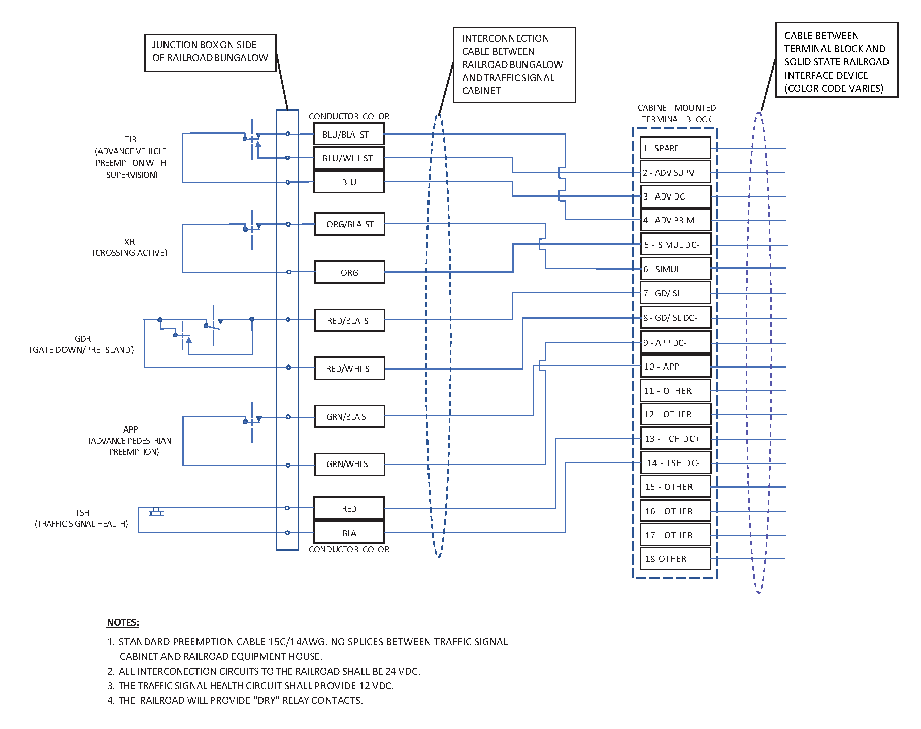
Figure 5–4. Railroad Wiring Diagram