Section 5: Railroad Interconnection Standards
Active-Style Interface Specification
General
The traffic signal system shall provide a solid-state, modular interface. Optimum functionality and safety features are achieved when the modules are installed in a standalone companion input file rack with module insertion verification protection. The companion input file rack shall provide two to four slots for the preemption system modules. Unless otherwise stated, the contractor shall furnish a standalone companion input file rack with module insertion verification protection for the railroad preemption. The interface shall function as follows:
- The railroad preemption system shall operate from nominal 120 Vac power applied via the companion input file rack or the input file pins.
- Each interconnection circuit to the railroad warning system shall operate on 24 Vdc and be isolated from all traffic signal cabinet internal voltage sources, AC line, grounds or AC neutral.
- The railroad preemption system shall generate the isolated 24 Vdc supply for the interconnection circuits.
- Each input from the railroad shall be optically isolated from other inputs and not referenced to any traffic signal cabinet internal voltage sources, AC line, grounds or AC neutral.
- The railroad preemption system shall provide a Traffic Signal Health isolated output. This output shall be an isolated 12 Vdc and shall be energized when Traffic Signal Health as described below is valid. The system shall monitor the 120 Vac load switch signal bus control circuit. In addition, the system shall monitor an appropriate signal output to sense “soft flash” operation. Soft Flash is flashing operation generated by the controller unit by providing outputs to the load switches that are turned off and on to develop the specific flash pattern. These two inputs shall be referenced to 120 Vac Neutral. If the signal bus becomes de-energized or flashing operation is sensed, the system shall de-energize the Traffic Signal Health output to the railroad.
- The railroad preemption system shall provide outputs referenced to controller unit logic ground for selection of programmed functions.
Supplemental Terminals
All supplemental terminals provided as a part of the railroad preemption interface shall utilize a "cage-clamp" design, such as manufactured by WAGO Corporation or equivalent. Terminals which provide "side wipe" connections or set screws are not acceptable. Terminal shall provide a minimum of 25 slots for railroad inputs.
Preemption System Isolator Modules
Each module providing preemption outputs shall be a processor-based unit. At least one module shall incorporate an organic light-emitting diode (OLED) display to indicate unit status, inputs, outputs and system timing. Modules shall be provided with an internal power supply to operate from the 120 Vac source. The combined railroad preemption interface system, including all modules, shall provide the following functions and features:
For preemption outputs and health monitoring:
- Input for 120 Vac signal bus (load switch power).
- Input for 120 Vac flashing signal indication for soft flash sense (soft flash indication).
- 12 Vdc isolated output to drive railroad vital relay for Traffic Signal Health.
- Isolated option input for Preemption Clearance Interval(s) monitoring from traffic signal load switch outputs.
- Input isolation for Advance Preemption, Supervised, Crossing Active and Gate Down from railroad warning system.
- Isolated option for Advance Pedestrian Preemption (APP), Gate Up, Island from railroad warning system.
- Outputs (six) for the traffic signal controller unit to select preemption plans.
- Output (advance) for control of blank-out signs or other devices.
- Output (simultaneous) for control of blank-out signs or other devices.
For operation of blank-out signs:
- 120 Vac load switch circuitry for an input file rack
- 4 Isolated circuits
- Ground true input provides 120 Vac output
- LED output channel status
- Self-supplied 24 Vdc to module rack
Railroad Preemption Isolator Module Input File Rack
The input file rack provides slots for the railroad preemption system isolator modules. The input file rack shall provide module insertion verification relay protection on the processor module slot(s) to verify proper seating. An improperly seated or missing module will place a call to the traffic signal controller preemption plan programmed for flash operation.
Unless otherwise specified, the railroad bungalow shall be provided with isolated relay contacts for the interface. Solid state outputs from the railroad may be used as an option to the relay contacts as required by the railroad. The interface shall provide the circuits described as required and specified in the preemption interconnection design.
At interconnected traffic signals, the controller assembly shall provide the operation detailed below relative to the railroad preemption functionality and operation.
The controller assembly shall be provided with all hardware, software and firmware necessary to provide the operation described herein. The designer, contractor and/or traffic signal technician should closely review the functional requirements of the railroad preemption operation to assure that the equipment is capable of performing the functions as specified. In many cases, the railroad circuits have been designed to provide and support the specific functionality. As a result, no exceptions will be permitted to these requirements. The Traffic Management Section of the Traffic Operations Division (TRF-TM) should be contacted for any further clarification regarding the hardware specifications.
Railroad Preemption Cable
Cable Materials
A railroad preemption cable must be a 15-conductor cable having a polyethylene jacket. The cable jacket must be rated for 600 Vac and 75 degrees C.
The railroad preemption cable color code must conform to DMS-11110, Traffic Signal Cable, Type A cables, Table 1 and be assigned as shown in the following table:
Conductor No. | Color Code | Railroad Interface Field Terminal Connections | Conductor Identification |
|---|---|---|---|
1 | Black | TSH IN 5- | Health Status DC- |
2 | White | - | Spare |
3 | Red | TSH IN 5+ | Health Status DC+ |
4 | Green | - | Spare |
5 | Orange | XR IN 3 | Simultaneous DC- |
6 | Blue | TCR IN 1 | Advance DC- |
7 | White/black stripe | - | Spare |
8 | Red/black stripe | GD/ISLD IN 2 | Gate Down/Island |
9 | Green/black stripe | APP OUT 4 | Advance Pedestrian Preemption |
10 | Orange/black stripe | XR OUT 3 | Simultaneous |
11 | Blue/black stripe | TCR OUT 1 | Advance Primary |
12 | Black/white stripe | - | Spare |
13 | Red/white stripe | GD/ISLD OUT 2 | Gate Down/Island DC- |
14 | Green/white stripe | APP IN 4 | Advance Pedestrian Preemption DC- |
15 | Blue/white stripe | SUPR 1 | Advance Secondary |
The individual conductors in the cable shall:
- Be stranded and comply with IMSA 20-1
- Have polyethylene insulation
- Minimum 14 AWG
Installation Methods
Typically, the contractor is required to install the conduit and riser up to the junction box at the railroad signal house. The railroad may install the conduit under the tracks on a project-by-project basis. This should be defined during the design phase of the project.
Do not splice railroad preemption cable from controller cabinet to railroad cabinet. Terminate individual conductors with connectors in the controller cabinet. Provide identification on both ends of the cable.
Keep all exposed conductors the same length and individually insulate spare conductors against each other.
Provide a minimum 6 feet of slack in the pull box adjacent to the railroad cabinet.
Connect the cable end in the railroad cabinet as directed by the railroad agency representative.
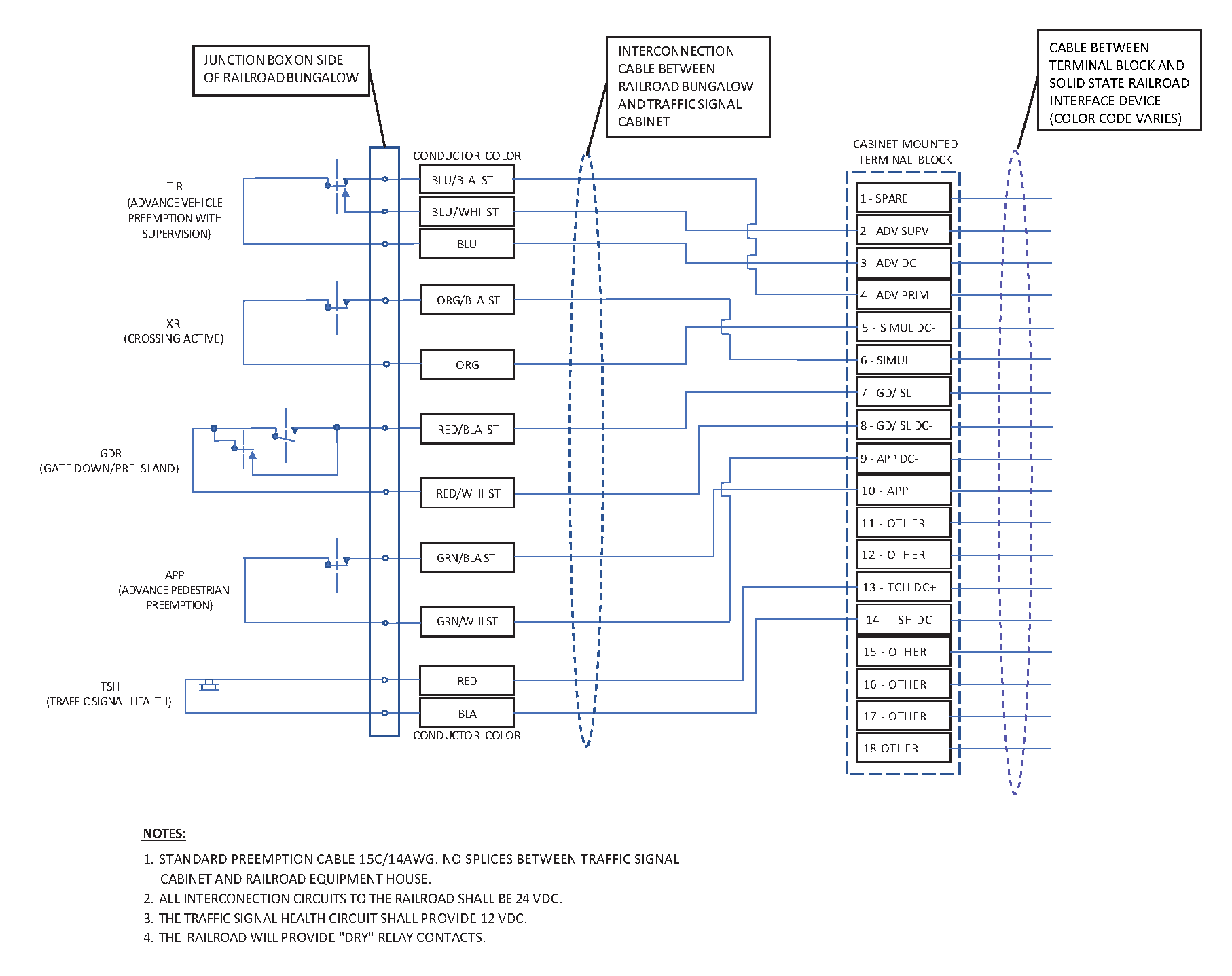
Figure 5–4. Railroad Wiring Diagram
Uninterruptible Power Supply/Battery Back-up System
To maintain orderly and safe vehicle, pedestrian and bicycle movements at signalized intersections interconnected with a railroad crossing it is recommended to provide uninterrupted, operation, avoiding black out or flashing red conditions, during a railroad preemption event. The TxDOT standard is to install a uninterruptible power supply/battery back-up (UPS/BBU) system at traffic signals that are interconnected to a railroad crossing. UPS/BBU systems at interconnected traffic signals shall provide at least 4 hours of continuous operation before transitioning to all-red flash operation.
Traffic Signal Communications
The TxDOT standard is to provide communications to traffic signals that are interconnected to a railroad crossing connecting them to a local Traffic Management System. Providing communication capabilities with the traffic signal facilitates allows for the collection of traffic signal event and alarm data and management of the traffic signal controller database. Other benefits of providing a communication link could include video surveillance of the intersection and crossing to collect data and observe driver behavior.
Special Scenarios
Where there are unique roadway configurations located near to the railroad tracks, preemption operations may need to be further evaluated to provide the appropriate traffic signal operations to effectively clear the tracks. For example, if a grade crossing is located adjacent to a diamond interchange, consideration should be given to clearing the space between the roadway intersections in addition to clearing the tracks. Figure 5-3 provides an example of how this can be accomplished. Note that when programming the preemptors, the signal technician must program the phases and overlaps for correct operation.