Chapter 4: Railroad Relays and Systems
Section 1: Railroad Relays and Usage in Traffic Signal Systems
Railroad Warning System
Per AREMA standards, the warning time the railroad provides in advance of the train’s arrival at the crossing is referred to as the Total Approach Time (TAT). TAT is comprised of several values as shown in Figure 4-1. Several of these values (Required Minimum Time, Clearance Time, Minimum Warning Time, and Advance Preemption Time) are included in Chapter 3 of this manual and are also defined in
. Key components that are not needed for preemption calculations but are necessary for determining TAT include the following as defined by AREMA.
- Buffer Time (BT) is the discretionary time that may be added by the railroad to account for variations in train handling.
- Equipment Response Time (ERT) is added to provide for variation in railroad equipment response time.
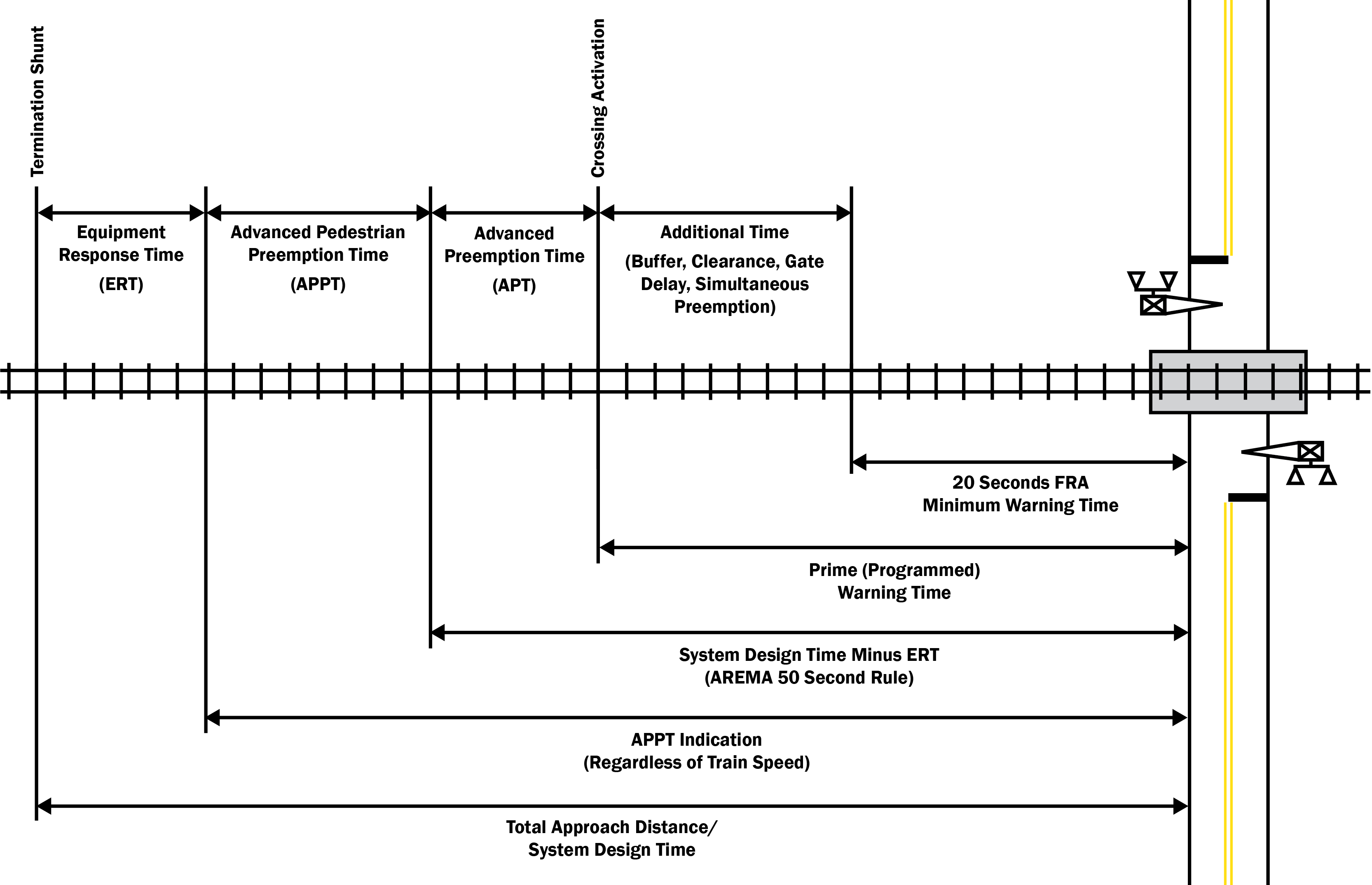
Figure 4–1. Typical Railroad Approach Timing Parameters
Railroads may use various types of detection systems to activate the railroad warning devices. Railroad detection systems generally consist of track circuits and island circuits. Track circuits are terminated by shunts on the tracks which are placed based on the required TAT as shown in Figure 4-1. Crossings with long railroad approaches and/or locations where multiple active warning crossings are in close proximity often use remote signal houses or DAX (Downstream Adjacent Crossing) locations.
Constant warning circuitry is used to provide more uniform warning times. Constant warning circuitry can detect the speed of an oncoming train to activate the railroad warning devices at the appropriate time. Constant warning circuitry also will deenergize the traffic control relay to communicate to the traffic signal controller to begin preemption. A major advantage of constant warning time is it predicts when to drop a preemption call if a train stops on the approach, as the case may be when a station or switch is located between the termination shunt and the grade crossing. Constant warning time may not be suitable for approaches where shunting is erratic due to rust or foreign material on the tracks. Future phases of positive train control (PTC) may add another potential detection type to railroad systems.
Railroad Relays
Traffic signal interconnection begins at the traffic signal cabinet with an output to the railroad signal house. Railroads use relays in a normally-closed (energized) or normally-open (deenergized) state to complete the circuit back the traffic controller.
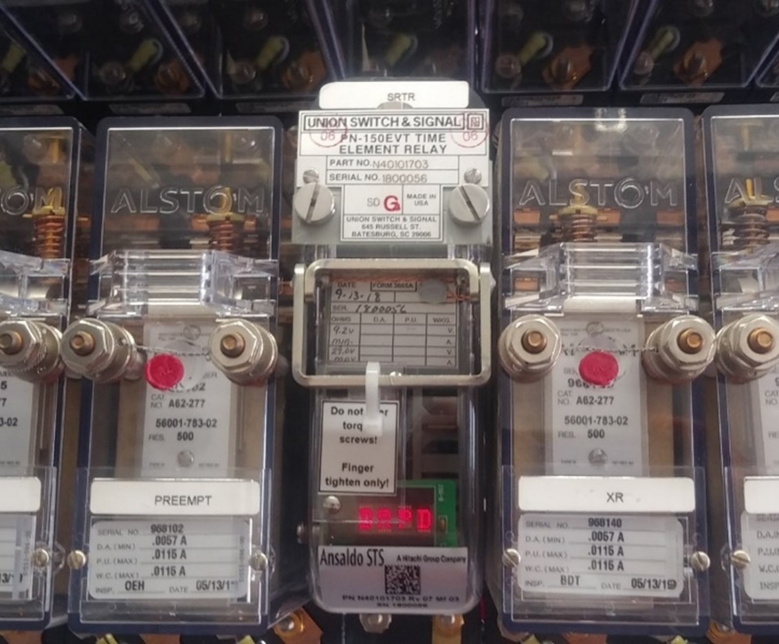
Figure 4–2. Railroad Relays
There are various railroad relays recommended by ITE and AREMA that the railroad may install to provide additional assistance in transitioning from normal to preemption operations. While not every relay is necessary for a successful and safe interconnected grade crossing, TxDOT recommends requesting them as they can transmit important information to the traffic signal controller, which can then respond more efficiently and reliably. Some railroad authorities also require certain relays to be installed alongside any new or modified interconnected grade crossings. These relays and their functions are outlined in Table 4-1 below.
Term | Abbreviation | Function |
|---|---|---|
Advance Pedestrian Preemption | APP | The advance pedestrian preemption relay is typically in a normally closed state. When activated, it notifies the traffic signal controller to finish serving pedestrian clearance on any active pedestrian phase (if applicable) prior to the start of the Preemption Clearance Interval for traffic signal modification projects or new installations. The advance pedestrian preemption relay shall be included where railroad interconnect and pedestrian clearance are needed and the track approach time (TAT) would otherwise violate the AREMA 50‑Second Rule (as defined in Section 5‑4). |
Advance Preemption / Traffic Control Relay | ADV/TCR | The advance preemption relay is in a normally closed state. When activated, it notifies the traffic signal controller to begin preemption operations and begin right‑of‑way transfer. The advance preemption relay shall be included at all interconnected traffic signals as they are modified, or as new signals are installed, unless the diagnostic team determines that simultaneous preemption is most appropriate. |
Crossing Active | XR | The crossing active relay is in a normally closed state. This relay acts as a re-start circuit for trains that are stopped within the approach where the full advance preemption time is not available. When activated, this relay notifies the traffic controller to immediately enter a special truncated preemption program to enter the Preemption Clearance Interval. Railroad warning equipment activates—flashers begin flashing and gates begin descending at the grade crossing. This circuit is often used to activate blank‑out signs during preemption. The crossing active circuit shall be included at all interconnected traffic signals as they are modified, or as new signals are installed. At locations without gates, this circuit should be used to terminate the Preemption Clearance Interval. |
Gate Down | GD | The gate down relay is in a normally open state. When activated, it notifies the traffic signal controller that the gates have descended to a nearly horizontal position, confirming that vehicles are physically restricted from entering the grade crossing area. Once the gates are down, the traffic signal must finish clearing vehicles that have already entered the crossing area. Upon serving any remaining Preemption Clearance Interval, the traffic signal controller terminates the interval and begins limited service operations. The gate down circuit shall be included at all interconnected traffic signals with railroad gates as they are modified or as new signals are installed to prevent a preemption trap. |
Island | ISLD/ISLR | The island relay is in a normally closed state. When activated, it notifies the traffic signal controller that the train has reached the grade crossing. Consequently, this circuit should only be used as a fail‑safe for the gate down circuit. It provides information for the traffic signal to transition to limited service operations. |
Supervision (Supervised) | SUPR | A supervised circuit is normally in the opposite state from the circuit it is supervising to monitor the interconnection between the railroad equipment and the traffic signal. If the connection is broken, the traffic signal shall begin preemption and enter a fault condition. The fault condition should be flashing red. The advance preemption circuit shall be supervised at all interconnected traffic signals as they are modified, or as new signals are installed. |
Traffic Signal Health | HLTH | The traffic signal health circuit notifies the railroad signal system of an unhealthy traffic signal system (for example, flashing‑red operation, power outage). If a problem exists, the railroad signal system can activate the railroad warning equipment sooner in order to safeguard the grade crossing. Traffic signal health shall be included at all interconnected traffic signals as they are modified, or as new signals are installed. |
Single Break and Double Break Circuits
states ” The preemption special control mode shall be activated by a supervised preemption interconnection using fail-safe design principles between the control circuits of the grade crossing warning system and the traffic signal controller unit.”
A single break circuit, as shown in Figure 4-2, is typically provided along with a supervision circuit to follow a fail-safe principle. This involves a deenergized and energized circuit. Both circuits change states when activated. If both circuits are energized or deenergized at the same time, this implies a faulty interconnection and the traffic signal shall immediately transition to preemption operations followed by a fault condition.

Figure 4–3. Single Break Circuit with Supervision
Per TMUTCD, “Instead of supervision, a double-break preemption interconnection circuit that uses two normally-closed circuits that open both the source and return energy circuits may be used.” Both are required A double break circuit schematic is shown in Figure 4-3 to change states in order to begin preemption. This provides a safety measure by ensuring that an electrical current will not mistakenly trigger a response and potentially transition to preemption by breaking both the positive and negative sides of the circuit.
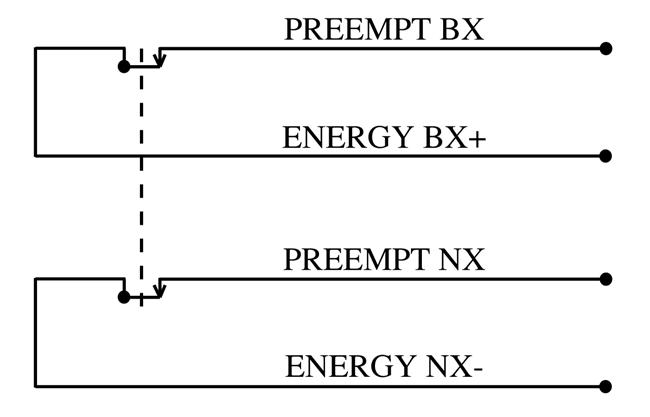
Figure 4–4. Double Break Circuit with Supervision
Although TMUTCD allows for either a single break supervised circuit or a double break circuit, the designer shall consider the type of traffic signal controller, preemption interface and the related software to ensure that the equipment is capable of handling those inputs. TMUTCD also dictates that “information regarding the type of preemption and any related timing parameters shall be provided to the railroad company or transit agency so that the railroad company or transit agency can design the appropriate train detection circuitry”.