13.4.4.1 Merge
Freeway entrance ramp merge areas are coded using connector lane change distance (LCD) in combination with a vehicle route. The effective merging area typically includes the entire auxiliary lane (or lane drop) to the farthest extent of the auxiliary lane taper and capture the full effective length used by vehicles. Vehicles in Vissim use the extra link length, when necessary, which more accurately models the use of the taper area. The merging or weaving section is typically one link with the number of lanes equal to the number of lanes on the main freeway plus the number of lanes merging onto the freeway. There can only be one connector downstream of the merge link or at the end of a lane drop section. There can be two connectors upstream of the merge link, one for the ramp link and one for the main freeway link. below shows an illustration of a merge segment.
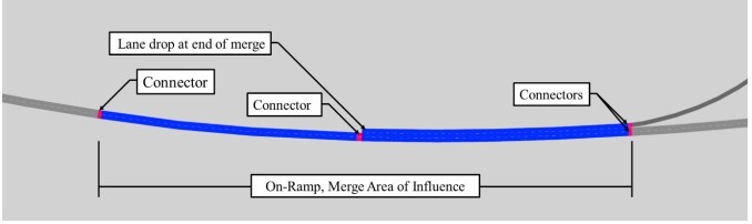
Figure 13-3: Freeway Merge Coding
The modeler typically uses the LCD of the connectors to accurately code the merge/weave area. One of the following two options can be implemented to avoid unrealistic lane changes on the freeway mainline into the acceleration lane:
- In the Connector dialog box, confirm the “Lane Change” distance for the connector downstream of the merge link is longer than the length of the merge area.
OR
- Indicate “No Lane Change” for the appropriate lane, using the Link dialog box.