12.1 Introduction
12.1.1 Purpose and Intended Use
The purpose of this chapter is to provide guidance to the user on how to perform a roundabout capacity analysis. This chapter discusses analyzing motorized vehicles as well as guidance on analyzing pedestrians and bicycles within the roundabout context. This chapter highlights typical MOEs and tools used for roundabouts, but it is not exhaustive in presenting available analysis alternatives. This chapter is best used during Planning and Preliminary Schematics.
12.1.2 Limitations
The methods of analyzing roundabouts described in the chapter are primarily based on the HCM 7th Edition. As such, this chapter highlights motorized vehicle analysis while multimodal considerations are limited to level of traffic stress and LOS. Furthermore, this chapter only briefly reviews safety analysis of roundabouts. For more information on safety analysis of roundabouts, see
Chapter 5 and Chapter 6
. This chapter provides roundabout-specific guidance on Microsimulation (Microscopic) analysis, which can be used to verify results of the empirical method found in the HCM 7th Edition. For general guidance on microsimulation (microscopic) analysis, see Chapter 13
.12.1.3 Intersection Control Evaluation
The Intersection Control Evaluation (ICE) process as described in
Chapter 10
and Chapter 11
, provides a framework of quantifiable and qualitative measures to evaluate intersection control alternatives so that public agencies, engineers, and planners can make evidence-based decisions. TxDOT employs ICE to determine intersection control type including roundabout feasibility. Roundabout analysis is a part of the ICE process. Roundabout attributes are described in the following sections.12.1.4 Safety
The reduction in vehicle speeds, conflict angles, and conflict points in a roundabout enhances vehicular and pedestrian safety. Roundabouts provide additional safety for bicyclists due to the slower vehicular speeds, which result in a smaller speed differential between bicyclists and motor vehicles. See
Chapter 5, Chapter 6, Chapter 10, and Chapter 11
for more information on roundabout safety analysis.12.1.5 Roundabout Categories
Roundabouts are an increasingly common form of intersection control that are typically circular, use yield control, and have geometric features that promote desirable vehicular speeds and provide accessibility to all roadway users. Common geometric features of a roundabout include a central island, traversable apron, splitter islands (channelizing islands), a circulatory roadway, entrance lines, pedestrian crossings, and landscape strips. There are three types of modern roundabouts:
- . Mini-roundabouts;
- Single-lane roundabouts; and
- Multilane roundabouts
Roundabouts vary in size, with mini-roundabouts and compact roundabouts ranging from 70 feet to 110 feet in inscribed circle diameter (ICD). Single lane and multilane roundabouts range from 110-feet to 200-feet ICD (refer to
RDM Chapter 14
). Geometric elements of roundabouts, e.g., are only partially addressed in part with the available operational analysis models. Number of entry lanes is dominant key predictive variable of roundabout capacity. Roundabouts can handle a wide range of vehicular volumes and provide operational and safety benefits in many circumstances.
shows the typical mini-roundabout features, shows the typical single-lane roundabout features, and shows the typical multilane roundabout features. For information regarding other roundabout design principles, refer to
RDM Chapter 14
and NCHRP 1043, Chapter 2. For information regarding roundabout interchanges, see Chapter 11
in this manual.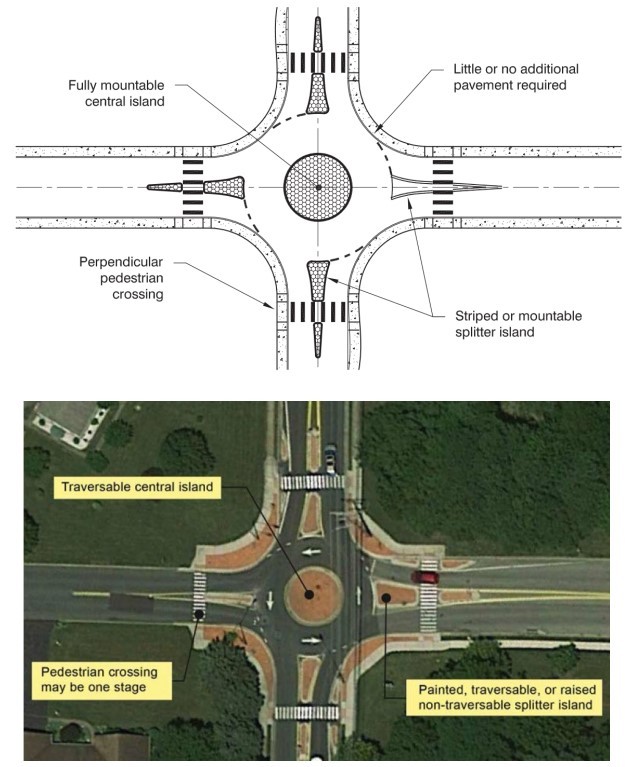
Figure 12-1: Features of a Typical Mini-Roundabout
Source: NCHRP 672 Exhibit 1-10 and NCHRP 1043 Exhibit 2.10
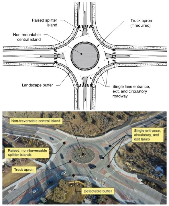
Figure 12-2: Features of a Typical Single-lane Roundabout
Source: NCHRP 672 Exhibit 1-12 and NCHRP 1043 Exhibit 2.15
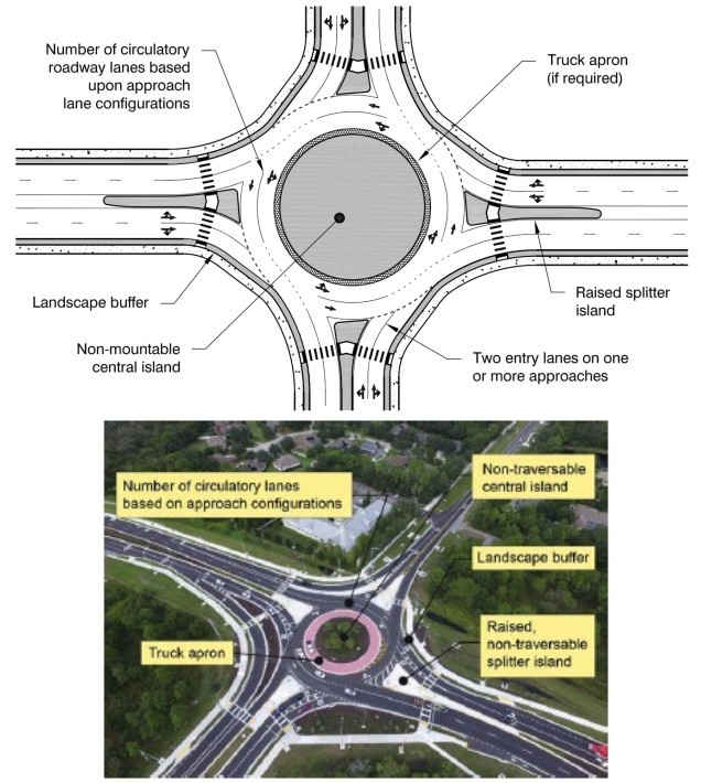
Figure 12-3: Features of a Typical Multilane Roundabout
Source: NCHRP 672 Exhibit 1-14 and NCHRP 1043 Exhibit 2.18
12.1.6 Overview
Roundabout analysis begins with determining whether a roundabout is an appropriate intersection control method for a particular location. See
Chapter 10
for guidance on undertaking the ICE process. The prescribed methods in this chapter focuses on roundabout analysis for motorized vehicles, pedestrians, and bicycles. Various methods of analysis are available for the two stages of project development and are discussed in this chapter. See for the selection of an appropriate analysis tool according to the project planning and schematic development phases of the project development processStage of Project Development Process | Application | Input Data Needed | Potential Operational Analysis Tool |
|---|---|---|---|
Intersection Control Evaluation (ICE) Stage 1 | Sizing of roundabouts – single lane versus multilane | Peak hour traffic volumes | CAP-X, Appendix M |
Intersection Control Evaluation (ICE) Stage 2 and Subsequent Geometric Design Refinement | Conceptual design of roundabouts with configurations within the scope of the HCM | Peak hour traffic volumes, lane configuration (multilane) from Appendix M | HCM 6 Capacity Methodology (HCS, Synchro) and other deterministic software models, e.g., Junctions , Sidra |
Conceptual analysis of bicyclist and pedestrian quality of service | Vehicular traffic, bicycle and pedestrian volumes, crosswalk design and traffic control | Techniques in NCHRP 1043 Chapter 9.8 | |
System analysis with two or more closely spaced intersections | Traffic volumes, lane configuration, intersection spacing and geometry | Simulation (Synchro SimTraffic, Vissim, etc.) |