11.2 Interchange Configuration Evaluation (ICE) - Context
Interchange and intersection are exchangeable terms in the ICE process. According to FHWA, ICE (see
Chapter 10
and Appendix K, Section 7
), ICE is a tool that uses data and performance metrics to analyze interchange control and geometric options. ICE provides a transparent and traceable decision process to compare alternative intersection types. Using quantifiable measures (safety, capacity and cost) to evaluate alternatives so that public agencies, engineers, and planners make enhanced and more informed decisions. Quantitative measures are considered alongside qualitative measures such as multimodal needs and community vision goals to provide a balanced perspective when selecting the preferred alternative. It is recommended that the preferred alternative is context-sensitive to its surroundings and users. See FHWA’s website under Appendix K, Section 7 – External References
for additional technical materials, tools, and information on the ICE framework. TxDOT’s RDM covers additional guidance for TxDOT’s approach to alternative intersection design. A link to the RDM is found in Appendix K, Section 7
. Chapter 10
outlines additional ICE process criteria and applicability. Appendix K, Section 1
provides an example of an abbreviated ICE report that applies when the ICE results are clear-cut at Stage 1 with safety as an overriding criterion for intersection control selection.11.2.1 Types of Interchanges
There are many types of interchanges. This chapter focuses on seven common interchange types (five of which are covered in the HCM): conventional diamond, contraflow left, DLT— diverging diamond, single-point urban, roundabout, Michigan Urban Diamond, and partial cloverleaf. For descriptions on other interchange types, refer to the RDM and FHWA’s Alternative Intersections/Interchanges: Informational Report (AIIR) (see
Appendix K, Section 7
).A
diamond interchange
is the most common type of interchange in Texas. At a diamond interchange, both directions of a major road intersect with the same cross street at separate locations, creating two closely spaced intersections. A diamond interchange demands less land area than other interchange types. The distance between intersections in urban and suburban settings is typically a minimum of 300 feet. There are several types of diamond interchanges: conventional, reverse, and spread.At a
conventional diamond
, either freeway ramps or frontage roads intersect at grade with the cross street. The intersection of freeway ramps or frontage roads with the cross street can either be controlled by All-Way Stop-Control, Two-Way Stop-Control, Signalization, or Roundabouts. The exit ramp before the intersection is followed by an entrance ramp after the intersection. shows a conventional diamond interchange. shows a diamond interchange with frontage roads.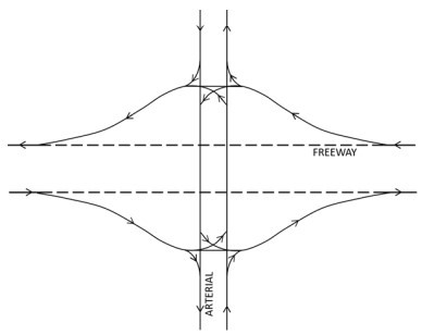
Figure 11-1: Conventional Diamond Interchange
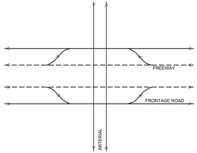
Figure 11-2: Diamond Interchange with Frontage Roads
At a
reverse diamond
or X ramp arrangement
, the exit and entrance ramp locations are flipped so that exiting and entering freeway traffic does not have to pass through the controlled intersections at the cross street or surface level, which reduces queues and delay at intersections. shows a reverse diamond interchange. At a spread diamond, the intersections are placed farther apart to improve sight distance and operations.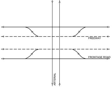
Figure 11-3: Reverse Diamond Interchange
A
contraflow left
interchange is similar to a conventional diamond interchange. However, the left-turn lane on the arterial crosses the opposing left-turn lane via channelized lanes. shows a line diagram with the movements of a contraflow interchange configuration. Contraflow interchanges are useful in areas where there are heavy left-turns from the arterial onto the frontage road and there is not enough space to add dual left-turn lanes. This type of interchange helps overall traffic operations by providing additional queuing space for left-turn lanes and increases efficiency of the signal operations. As with most alternative interchanges, there can be issues with driver expectancy. Drivers turning left from the frontage road may be inclined to turn into the nearest lane, which would be the opposing left-turn lane. Adequate signage and striping is provided for this design to avoid instances where drivers choose the wrong lane.A
Displaced Left Turn (DLT)
interchange previously called a CFI is similar to a contraflow left interchange, but instead of the left-turn lanes crossing each other, the left-turn lanes cross the opposing through lanes in advance of the intersection. shows a line diagram of the movements for a DLT. This configuration allows left turns and opposing through movements to run concurrently, which increases overall efficiency and reduces delay. A DLT also improves safety by spreading out the number of conflicts rather than concentrating them at one location. Drivers may find navigating through a DLT challenging at first, as alternative interchanges are not commonly encountered by most drivers. There are several variations of the CFI, one of which is called the parallel flow interchange, which moves the bypass road adjacent to the cross street instead of adjacent to the approach road. This type of interchange is recommended to be examined when there are heavy left-turn volumes onto the freeway ramps.%20Interchange.jpg/_jcr_content/renditions/cq5dam.web.1280.1280.jpeg)
Figure 11-4: Displaced Left Turn (DLT) Interchange
Source: Virginia Department of Transportation, 03/05/2024
At a
Diverging Diamond Interchange (DDI)
, sometimes referred to as the double crossover diamond (DCD) interchange, ramps or frontage roads along both sides of a freeway intersect with the same cross street at separate locations, creating two closely-spaced intersections like a diamond interchange, as shown in . The major difference is that, at a DDI, traffic on the cross street externally crosses over to the other side of the street at one intersection and crosses back at the next intersection. This reduces the number of left-turn conflicts by allowing easier access to and from the freeway. Left-turning vehicles from the cross street do not conflict with approaching vehicles from the ramps. Capacity may be adjusted with two-phase signal operations coordinated between crossover intersections. Refer to NCHRP 959 Diverging Diamond Interchange Informational Guide and TxDOT’s Diverging Diamond Interchange Fact Sheet
(provided in Appendix L, Section 2 – DDI Factsheet
) for more information. TxDOT’s RDM (see Appendix E
) covers additional guidance for TxDOT’s approach to DDI design..jpg/_jcr_content/renditions/cq5dam.web.1280.1280.jpeg)
Figure 11-5: Diverging Diamond Interchange (DDI)
Source: Virginia Department of Transportation, 03/05/2024
At a
single-point urban interchange (SPUI)
, one major intersection is created with the freeway ramp left-turn movements and the cross street through and left-turn movements, shown in . All the right turns are channelized. Freeway mainlanes are grade separated from the intersection. Because a SPUI only has one main intersection, it typically uses less space and simpler traffic signal phasing than the conventional diamond. Phasing has three movements: through movements on the cross street, left turns in one direction, and left turns in the other direction. A SPUI may also accommodate the through movement on frontage roads and/or freeway ramps. However, these movements are separated from the intersection and could be costly. The length of the bridge span for a SPUI is typically 160 to 280 feet. Refer to TxDOT’s Single-Point Urban Interchange Fact Sheet
(provided in Appendix L, Section 3 – SPUI Factsheet
) for more information.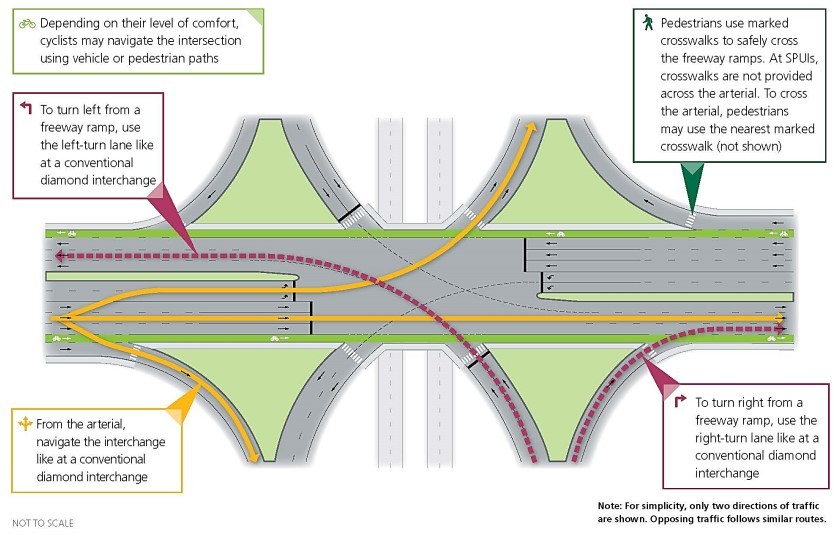
Figure 11-6: Single Point Urban Interchange
Source: Virginia Department of Transportation, 03/05/2024
At
roundabout interchanges
, there are three main design types: a conventional double roundabout, a raindrop-shaped double roundabout, and a single-point roundabout. The main difference between the conventional and raindrop-shaped roundabout is the conventional roundabout permits U-turns on the cross street at the nodes and accommodates an additional approach. The rain-drop configuration is less desirable because it prevents U-turns and mixes yield control with free-flow regulation of priority. shows the double roundabout interchange. See Chapter 12
or NCHRP Report 1043, Section 10.10 for additional information on roundabout interchange analysis.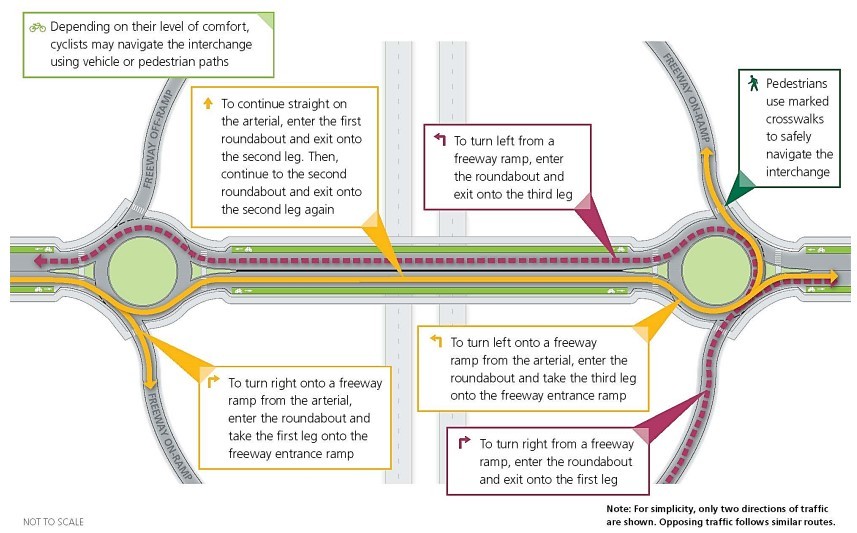
Figure 11-7: Double Roundabout Interchange
Source: Virginia Department of Transportation, 03/05/2024
The single-point roundabout interchange is preferred in areas with ROW constraints and moderate volumes. Single-point roundabout interchanges typically demand larger and multiple bridge spans to accommodate the circle size and sight distance requirements for circulating vehicles. shows the single-point roundabout interchange. Roundabout interchanges have been proven as a safety improvement compared to signal control and stop control ramp intersections. This type of interchange could also reduce delay when operating within appropriate range of design volumes, particularly during off-peak hours. They demand fewer lanes (narrower bridge cross-sections) and no signal coordination between the closely spaced ramp intersections. As with all interchange configurations, it is recommended that operational analysis consider potential queue spillback.
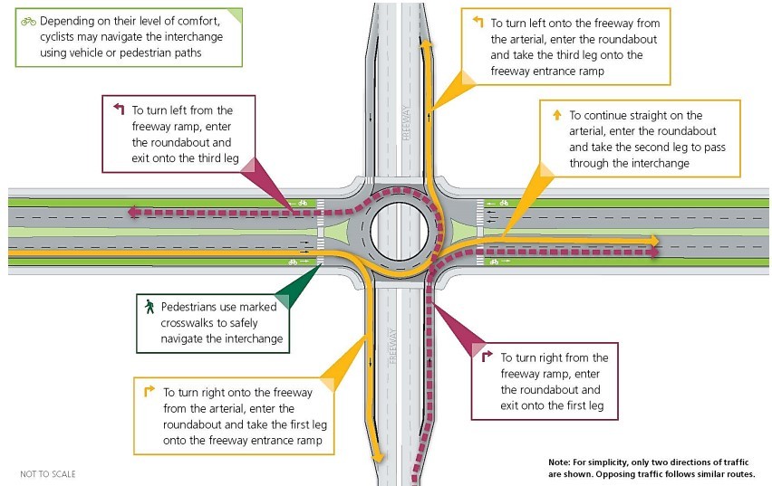
Figure 11-8: Single-Point Roundabout Interchange
Source: Virginia Department of Transportation, 03/05/2024
The
Michigan Urban Diamond Interchange
facilitates traffic flow and safety by redirecting traditional left-turn movements: drivers intending to turn left onto and off the freeway make a right turn followed by a U-turn at a designated crossover. Right turns are executed in a standard manner, both onto and from the freeway. Through traffic on the arterial road proceeds as it would at a conventional diamond interchange. Pedestrian movement is safeguarded through marked crosswalks, while cyclists have the option to navigate using either the vehicular or pedestrian paths, based on their comfort level. The interchange design aims to streamline vehicular movements, reduce conflict points, and enhance overall traffic efficiency within a compact urban layout. shows a Michigan Urban Diamond Interchange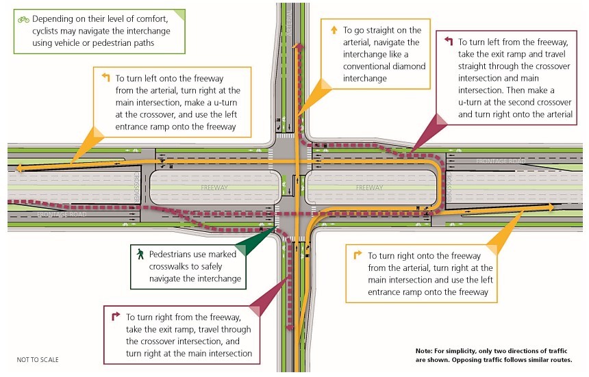
Figure 11-9: Michigan Urban Diamond Interchange
Source: Virginia Department of Transportation, 03/05/2024
At a
cloverleaf interchange
, traffic uses rightturn loop ramps and directional ramps to move between both directions of the cross street and freeway mainlanes, shown in and . A full cloverleaf interchange eliminates all left-turn conflicts (conflict points are a measure of the potential threats of two intersecting roadway configurations). Please note, the full cloverleaf design is not included in HCM 7th Edition due to its freeway-tofreeway interaction. A partial cloverleaf has loops in one to three quadrants:
- In partial cloverleaf A interchanges, major street loop ramps are in advance of the minor street.
- In cloverleaf AB interchanges, major street loop ramps are located on the same side as the minor street. This type of cloverleaf is shown in .
- In cloverleaf B interchanges, major street loop ramps occur beyond the minor street. This type of cloverleaf is shown in .
Cloverleafs are categorized between four and two quadrant partial interchanges. These four quadrant interchanges are addressed as parclo A4 and B4. Parclo A4 contains six ramps and two slip lanes that aid in releasing traffic congestion entering the highway from the arterial. Similarly, B4 mirrors A4, however favors traffic exiting the highway. The two quadrant partial interchanges, A2 and A4 contain four ramps and intend to aid traffic congestion on the highway onto the arterial.
Cloverleaf interchanges are not preferred in locations with high interchange volumes or leftturn volumes exceeding 1,200 passenger cars per hour because loop ramps are usually one lane and have much lower speeds, especially for trucks. Ideally, cloverleaf interchanges can be installed when frontage roads are present for more satisfactory operations. HCM methodology, or other similar methods, may be applied to partial cloverleaf interchanges with either signal or roundabout control.
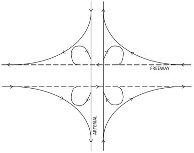
Figure 11-10: Full Cloverleaf Interchange
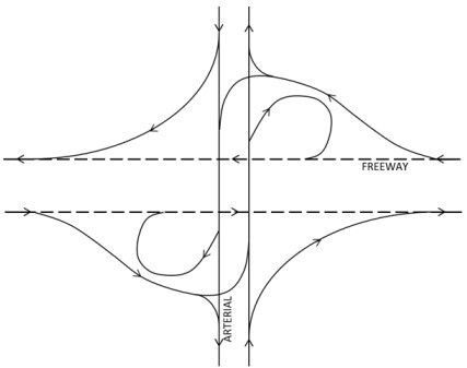
Figure 11-11: Partial Cloverleaf A (4 quadrant) Interchange
.jpg/_jcr_content/renditions/cq5dam.web.1280.1280.jpeg)
Figure 11-12: Partial AB (4 quadrant) Cloverleaf Interchange
.jpg/_jcr_content/renditions/cq5dam.web.1280.1280.jpeg)
Figure 11-13: Partial B (2 quadrant) Cloverleaf Interchange
An interchange is often selected based on operational results from tools like CAP-X, HCS, or safety results from HSM-based tools. Initial screening can be done by referencing , which provides information on the benefits of each interchange type and considerations for selecting one. For more information on interchanges, see
Appendix L, Section 4 – External References
Interchange Type | Interchange Type | Benefits |
|---|---|---|
Diamond or “X” |
|
|
Contraflow Left |
|
|
Displaced Left Turn (DLT) |
|
|
Diverging Diamond |
|
|
Single Point Urban Interchange (SPUI) |
|
|
Single Roundabout |
|
|
Double Roundabout |
|
|
Partial Cloverleaf |
|
|