10.2 Intersection Control Evaluation (ICE) - Context
ICE, the process and analysis tools, is necessitated by the appearance of roundabouts and alternative intersection designs (RAID). The (ICE) process is used in evaluating the intersection traffic and geometric control at new or modified intersections. This chapter covers the main intersection types, evaluation process, analysis tools, and their inputs and outputs. Intersection Control Evaluation tools can be seen under
Appendix K, Sections 1, 2, and 8
.According to FHWA, ICE (see
Appendix K, Section 8
), (ICE) is a tool that uses data and performance metrics to analyze intersection control and geometric options. ICE provides a transparent and traceable decision process to compare alternative intersection types. ICE is performed during the planning and schematic development phase; however, it is subject to changes until after the environmental documents are finalized and/or ROW acquisition is authorized. Using quantifiable measures (such as safety, capacity, cost, and impacts) to evaluate alternatives, public agencies, engineers, and planners can make more informed decisions. Quantitative measures are considered alongside qualitative measures such as multimodal needs and community vision goals to provide a balanced perspective when selecting the preferred alternative. It is recommended that the preferred alternative is context-sensitive to its surroundings and users. See FHWA’s website under Appendix K, Section 8 – External References
for additional technical materials, tools, and information on the ICE framework.TxDOT’s RDM covers additional guidance for TxDOT’s approach to alternative intersection design. A link to the RDM is found in
Appendix K, Section 8 – External References (Reference 9)
.10.2.1 ICE Workflow
The ICE process fits into project development at the earliest stages, considering all practical and feasible intersection or interchange alternatives to produce a traceable and transparent evidence-based method of proving the choice and design of an intersection/interchange. and illustrate the stages of the ICE process in the early stages of project planning.
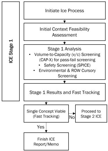
Figure 10-1: ICE Stage 1 in the Project Workflow
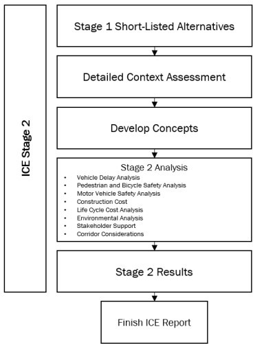
Figure 10-2: ICE Stage 2 in the Project Workflow
10.2.2 ICE Applicability
ICE does not apply to development of studies or projects that involve system optimization, which is common for post-construction finetuning of operations. However, ICE is completed under the following circumstances:
- The intersection includes a roadway designated as a State route or as part of the National Highway System.
- The intersection or corridor improvements present opportunity to change the type of intersection or control to improve safety and/or operations.
- The intersection will be designed or constructed using State or Federal funding.
ICE does not need to be completed (but may be considered), under the following circumstances:
- The proposed work does not increase the vehicular footprint (as through-put) of the intersection, such as:
- sidewalk/streetscape improvements;
- signal permit revision;
- minor turn lane adjustments, such as converting a short section of shoulder to a turn lane or lengthening a turn lane; and
- resurfacing
- Local road intersection where the proposed condition is a right-in and right-out.
- Where routine traffic signal timing and equipment maintenance is required, such as where the build condition is being improved with signal timing optimization.
Driveway permits:
A District has the authority to make the determination as to when ICE needs to be performed for a driveway permit.For corridor improvement projects with multiple intersections that are likely to need a change in control to maintain operations or improve safety, ICE is applied to each intersection, but with a view to the corridor as a system. For example, it is common to use combinations of roundabouts, R-CUT and medians that restrict turning movements in or out of minor intersections or driveways. With combinations of roundabouts, the U-turn movements that are generated by an R-CUT can be accommodated more safely, especially for slow moving vehicles affected by an R-CUT
When a corridor collection of individual ICE analyses represents a system level review, documentation is recommended in the form of a summary memo that combines results and explanation of how adjacent intersection controls are interdependent, e.g., R-CUTs combined with roundabouts for U-turns.
10.2.3 Intersection Types
The analysis methods in this chapter apply to the following intersection types (see Chapter 11 for Interchanges). Unique and alternative designs are presented in the sections that follow:
Signalized:
- Conventional Signal (Isolated, Coordinated, Clustered);
- Signalized RCUT;
- Quadrant Roadway;
- Turn lane Improvements;
- DLT; and
- CGT
Unsignalized:
- TWSC;
- All-way Stop-controlled (AWSC);
- Single Lane Roundabout;
- Multilane Roundabout;
- RCUT – Unsignalized;
- RIRO w/Downstream U-Turn;
- High-T (unsignalized Green Tee); and
- Turn Lane Improvements
Basic descriptions of intersection types (i.e., geometric configuration, operational considerations, and safety considerations) are provided below. See provides general considerations for intersection type and the benefits each intersection type provides. Determining which type of intersection is being evaluated will help define which analysis tools to use.
Appendix K, Section 2 – Intersection Type Additional Resources
lists additional resources used to understand various intersection types. Appendix K, Section 7 – Intersection Type Graphics
shows additional alternative intersections and Appendix K, Section 8 – External References (Reference 11)
provides a link to an alternative intersection inventory in TexasIntersection Type | When to Consider | Benefits | Disadvantages |
|---|---|---|---|
Conventional Signalized (Isolated) |
|
|
|
Conventional Signalized (Coordinated) |
|
|
|
Conventional Signalized (Clustered) |
|
|
|
Two-Way Stop-Controlled (TWSC) |
|
|
|
All-Way Stop-Controlled (AWSC) |
|
|
|
Continuous Green-T (CGT) |
|
|
|
Roundabout (See Chapter 12 for more information) |
|
|
|
Median U-Turn (MUT) |
|
|
|
Restricted Crossing U-Turn (RCUT) |
|
|
|
Displaced LeftTurn (DLT) |
|
|
|
Grade-Separated Intersection |
|
| Could be more costly than other intersection alternatives |
10.2.3.1 Signalized Intersection
Compared to unsignalized intersections, signalized intersections increase capacity, reduce right-angle crashes, and permit vehicles, pedestrians, and bicyclists from minor volume approaches to safely cross an intersection. However, they create off-peak delay to minor approaches, increase frequency of rear-end crashes, increase congestion, and have high maintenance costs. TMUTCD signal warrants are recommended to be met before an intersection is converted into a signalized intersection. Signalized intersections are comprised of the following subcategories: isolated, coordinated, and clustered.
10.2.3.2 Coordinated Signalized Intersection
Coordinated intersections include two or more intersections that promote progression between each other along a corridor. According to the National Association of City Transportation Officials’ (NACTO’s) Urban Street Design Guide, coordinated intersections are typically spaced one-half mile or less apart and provide more continuous traffic flow for major street users going from one coordinated intersection to the next. Coordinated intersections can be optimized to a specific target speed to meet the lower speed needs of bicyclists and pedestrians.
10.2.3.3 Cluster Intersection
According to the HCM, groups of two or more intersections that are closely spaced and work operationally together using displaced or distributed movements are clustered intersections. It is recommended that these intersection clusters be analyzed as one system. Most alternative intersections are made of clustered intersections due to left-turn or U-turn movements that occur either before or after the main intersection.
10.2.3.4 Continuous Green-T (CGT)
In a High-Tee (Unsignalized CGT) or CGT intersection, one major street movement passes through the intersection without stopping. This movement typically occurs on the opposite side of the side street (on top of the “T”). The other major street direction of travel is typically uncontrolled or controlled by a traffic signal. Vehicles turning left from the side street to the major street use a left-turn pocket and merge with the major street through traffic. CGT intersections are not suitable for highspeed roadways (> 55mph). CGT intersections can be difficult for pedestrians to cross. See for the basic features of a CGT.
.jpg/_jcr_content/renditions/cq5dam.web.1280.1280.jpeg)
Figure 10-3: Continuous Green-T Features (1)
Source: Virginia Department of Transportation, 03/05/2024
10.2.3.5 Restricted Crossing U-Turn (RCUT)
This alternative intersection can either have traffic signals or be stop controlled. RCUTs have directional medians to force minor street through and left-turning traffic to make a right-turn and then a U-turn on the major street to complete their maneuvers. When analyzing operations or safety of an RCUT intersection, the analysis typically includes the core intersection as well as the satellite intersections. See for the basic features of an RCUT intersection.
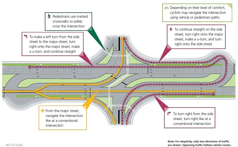
Figure 10-4: Restricted Crossing U-Turn Features
Source: Virginia Department of Transportation, 03/05/2024
10.2.3.6 Median U-Turn (MUT)
At MUT intersections, left-turning traffic on the major and minor street U-turn at wide medians to complete their maneuver. This eliminates the need for left turn phases at the intersection. When analyzing operations or safety of a MUT intersection, the analysis typically includes the core intersection as well as the travel time and delay at the satellite intersections. See for the basic features of a MUT intersection.
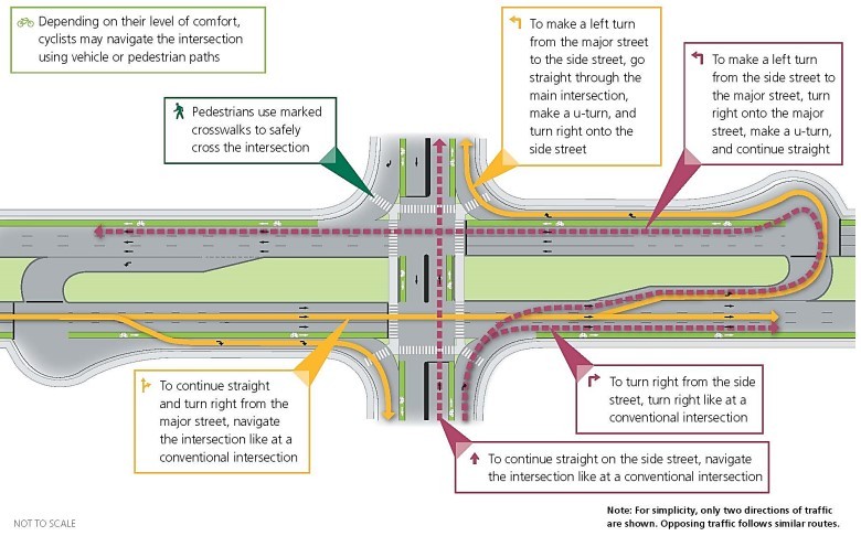
Figure 10-5: Median U-Turn Features
Source: Virginia Department of Transportation, 03/05/2024
10.2.3.7 Displaced Left-Turn (DLT)
Also known as a continuous flow interchange (CFI) or crossover displaced left-turn (XDLT), this signalized intersection type relocates one or more left-turn movements on an approach to the other side of the opposing traffic flow. Signals are placed at crossover intersections upstream of the main intersection and left-turn movements run simultaneously with the through movement, eliminating the need for a left-turn phase for that approach. When analyzing operations or safety of a DLT intersection, the analysis typically includes the core intersection as well as the satellite intersections. See for the basic features and flow patterns of a DLT. This intersection type requires restriction of access within the influence area of the layout. Right-in and right-right access may be permitted but not close to the cross-over areas
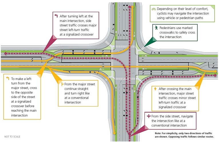
Figure 10-6: Displaced Left-Turn Features
Source: Virginia Department of Transportation, 03/05/2024
10.2.3.8 Two-way Stop-controlled (TWSC)
TWSC intersections are comprised of one uncontrolled street and one stop-controlled street (see ). A typical configuration of TWSC intersections is a four-leg intersection with an uncontrolled major street and a stopcontrolled minor street. Another typical configuration is a three-leg intersection where the third leg (minor street) is stop-controlled, and the major street is uncontrolled. TWSC are typically applied at locations with a large majority of overall intersection traffic occurring on the major street. Safety analysis of TWSC intersections is discussed in
Section 10.3
of this chapter or in Chapter 5
and Chapter 6
.
Figure 10-7: TWSC Intersection
10.2.3.9 All-way Stop-controlled (AWSC)
At AWSC intersections, all approaches have stop control (see ). AWSC are typically applied at locations with a balanced volume of vehicles traveling on intersecting segments. Operational analysis of AWSC intersections is dependent on traffic patterns at the intersection because delay at each approach is dependent on the arrival patterns of the other approaches. Safety analysis of Two-way Stop-controlled intersections is discussed later in this chapter and in
Chapter 5
and Chapter 6
.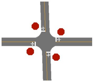
Figure 10-8: AWSC Intersection
10.2.3.10 Roundabouts
Roundabouts are circular intersections that use either signals or yield control and channelizing islands to circulate traffic in a counterclockwise motion around and through an intersection. The channelizing islands provide a refuge for pedestrians. The geometric features of a roundabout deflect and slow approaching vehicles. Roundabouts are designed to varying sizes from a single-lane mini-roundabout with a 90-foot inscribed circle diameter to a multi-lane roundabout with a 200-foot inscribed circle diameter. An
example
of a roundabout is shown in . For more information about roundabouts (including example figures) and roundabout analysis, see Chapter 12
.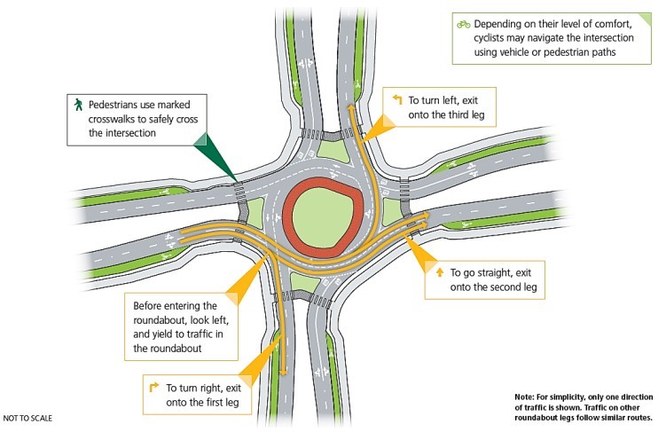
Figure 10-9: Roundabout Features
Source: Adapted from Virginia Department of Transportation, 03/05/2024
10.2.3.11 Grade-Separated
Grade separation is a method of aligning a junction of two or more roadways at different heights (grades) so that they will not disrupt the traffic flow on other routes when they cross each other. Grade separation is typically introduced for the major street through movement, while major street turning movements and all minor street movements still occur at the same grade. See for the basic features of a grade-separated intersection.
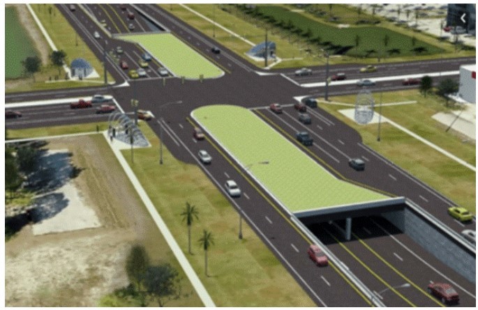
Figure 10-10: Grade Separated Features
Source: TxDOT Visual Dictionary - Grade Separation