8.1.6 Travel Lane Width and Number of Lanes
The minimum and usual main lane width is 12-ft. The number of lanes required to accommodate the anticipated traffic in the design year is determined by the level of service evaluation as discussed in the
. However, at a minimum, a freeway should have two through-traffic lanes in each direction of travel. See
for further information.
shows an alternative freeway section. The geometric dimensions shown in these figures represent examples of different conditions and may be adjusted in accordance with
.
8.1.6.1 Principle of Lane Balance
After the number of lanes has been determined, the balance in the number of lanes should be confirmed based on the following principles:
- At entrance ramps, the number of lanes on the highway beyond the ramp should be equal to the total number of approach lanes on the highway and the lanes on the ramp, minus one. However, it can be equal to the total number of highway approach and ramp lanes;
- At exit ramps, the number of approach lanes on the highway should be equal to the sum of all lanes on the highway beyond the ramp and the lanes on the exit ramp, minus one. Exceptions to this principle occur at clover leaf loop-ramp exits that follow a loop-ramp entrance and at exits between closely spaced interchanges. (Closely spaced interchanges are those where the distance between the end of the entrance terminal taper and the beginning of the taper of the exit terminal is less than 1,500- ft, and a continuous auxiliary lane between the terminals is provided). In these cases, the auxiliary lane may be dropped in a single-lane exit such that the number of lanes on the approach roadway is equal to the number of through lanes beyond the exit plus the lane on the exit;
- The traveled way of the highway should be reduced by not more than one traffic lane at a time;
- To satisfy lane-balance at two-lane exits, an auxiliary lane upstream of the exit should be provided; and
- To satisfy lane-balance at two-lane entrances, at least one additional lane should be provided downstream. This lane may be another through lane if needed for capacity or an auxiliary lane that may be reduced with the appropriate taper or at the next interchange.
Typical examples of lane balance are shown in
.
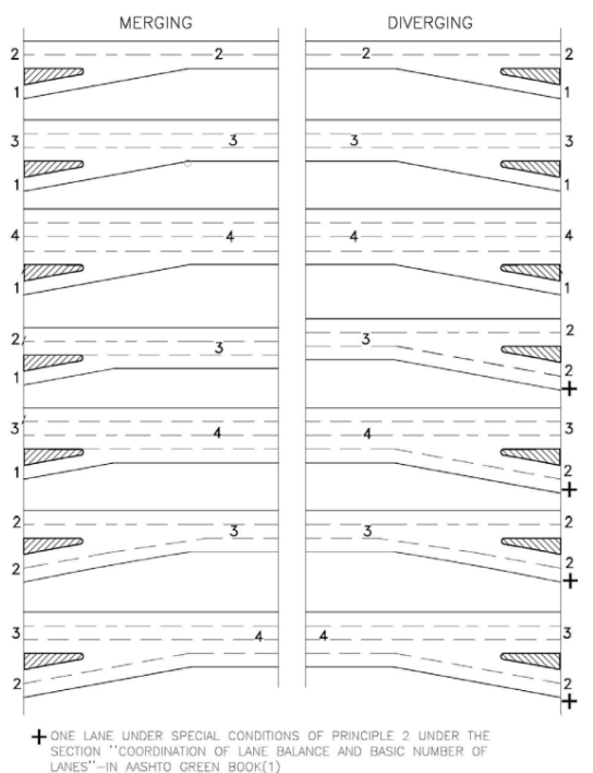
Figure 8-1 Typical Examples of Lane Balance
8.1.6.2 Left and Right Lane Drops
Sometimes it is necessary to reduce, or end, the number of through-travel lanes. When doing so, it is desirable to perform a lane drop at an exit ramp or a route split. When a lane reduction cannot take place at an exit ramp or route split, the lane reduction should occur in the outermost right through lane.
Left lane reductions should be avoided to minimize driver confusion.
When a left-through lane reduction is needed, the right lane should be dropped first, followed by a through lane shift or transition as shown in
. The concepts shown in
is applicable to facilities that have 3 or more mainlanes. Refer to
for further details. Refer to the latest version of the
, the
, and TxDOT’s
for additional guidance on signing and pavement marking design concerning lane drops.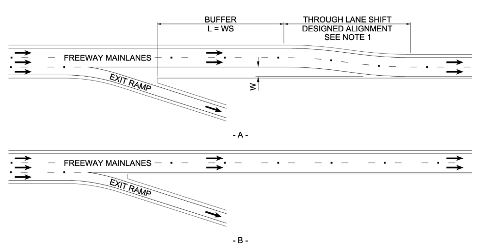
Notes:
- THE THROUGH LANE SHIFT SHOULD BE DESIGNE AS A HORIZONTAL ALIGNMENT IN ACCORDANCE WITH SECTION 4.7
- THIS IS NOT INTENDED TO SHOW STRIPPING OR PAVEMENT MARKING DETAILS.REFER TO THE TEXA MUTCD FOR ADDITIONAL INFORMATION.
- THIS FIGURE IS NOT INTENDED TO CONVEY LANE OR SHOULDER WIDTHS.REFER TO SECTION 8.1.7 AND 8.1.8 FOR LANE AND SHOULDER WIDTH INFORMATION.
- L = LENGTH OF BUFFERW = WIDTH OF OFFSET FOR THROUGH LANE SHIFTS= DESIGN SPEED
Figure 8-2 Preferred Left Through Lane Reduction Example
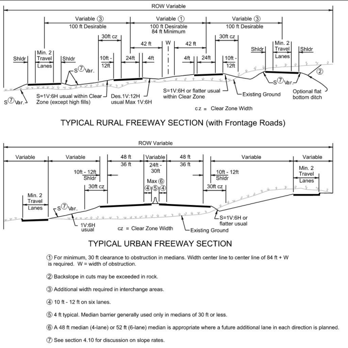
Figure 8-3 Typical Freeway Sections
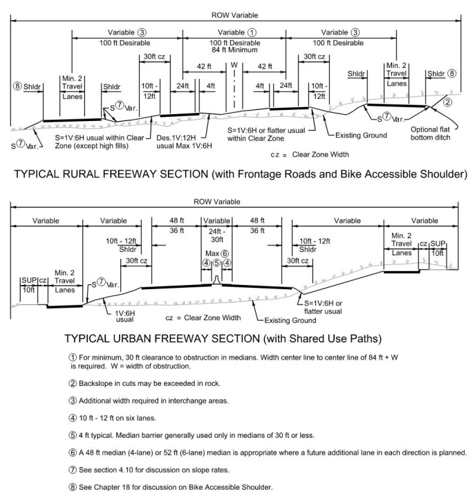
Figure 8-4 Alternative Typical Freeway Sections