4.3.3 Control Vehicles
Geometric design may also incorporate a control vehicle. The control vehicle is an infrequent but necessary user of the facility and informs what operations need to be accommodated in the design of the facility. The control vehicle is generally larger than a design vehicle. As an example, a facility may be designed for WB-67’s but may also need to account for oversized tractor trailers carrying large materials such as wind turbines. Adopting both a design vehicle and a control vehicle encourages a safer design that can accommodate frequent and infrequent users. To prevent the overdesign of a facility, the control vehicle should only dictate how the design might accommodate a larger vehicle’s needs when using the facility.
Typically, a design vehicle can turn using one incoming and one receiving lane, while the control vehicle can turn using multiple lane spaces. Engineering judgement should be exercised when determining how many lane spaces a control vehicle can use.
shows an example of how the turning movements can differ between a design vehicle and control vehicle.
Design Vehicle Type | Passenger Car | Single-Unit Truck | Single-Unit Truck (Three Axle) | Intercity Bus (Motor Coach) | City Transit Bus | Conventional School Bus (65 pass.) | Large School Bus (84 pass.) 1 | Articulated Bus | Intermediate Semi-trailer | |
Symbol | P | SU-30 | SU-40 | BUS-40 | BUS-45 | CITY-BUS | S-BUS36 | S-BUS40 | A-BUS | WB-40 |
Minimum Design Turn Radius (ft) | 23.8 | 41.8 | 51.2 | 41.7 | 44.0 | 41.6 | 38.6 | 39.1 | 39.4 | 39.9 |
Centerline Turning Radius (CTR) (ft) 4 | 21.0 | 38.0 | 47.4 | 37.8 | 40.2 | 37.8 | 34.9 | 35.4 | 35.5 | 36.0 |
Minimum Inside Radius (ft) | 14.4 | 28.4 | 36.4 | 24.3 | 24.7 | 24.5 | 23.8 | 25.3 | 21.3 | 19.3 |
Design Vehicle Type | Interstate Semi Trailer | "Double Bottom" Combinati on | Rocky Mtn Double | Triple Semi-trailer/ Trailers | Turnpike Double Semi- trailer / Trailer | Motor Home | Car and Camper Trailer | Car and Boat Trailer | Motor Home and Boat Trailer | |
Symbol | WB-62 2 & WB-62TX | WB-67 3 | WB-67D | WB-92D | WB-100T | WB-109D 2 | MH | P/T | P/B | MH/B |
Minimum Design Turn Radius (ft) | 44.8 | 44.8 | 44.8 | 82.0 | 44.8 | 59.9 | 39.7 | 32.9 | 23.8 | 49.8 |
Centerline Turning Radius (CTR) (ft) 4 | 41.0 | 41.0 | 40.9 | 78.0 | 40.9 | 55.9 | 36.0 | 30.0 | 21.0 | 46.0 |
Minimum Inside Radius (ft) | 7.4 | 1.9 | 19.1 | 55.6 | 9.7 | 13.8 | 26.0 | 18.3 | 8.0 | 35 |
Notes: | ||||||||||
| ||||||||||
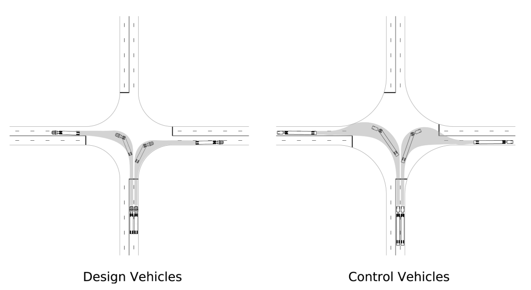
Figure 4-1: Lane usage for Design and Control Vehicle Turning Movements