13.10.1 Minimum Turning Radii
Application -
Although there are no firm guidelines governing the selection of the type of large vehicle to be used as a design vehicle, there is suggested guidance provided for urban and rural intersections near the end of this section. Factors that influence design vehicle selection are as follows:- Functional class of intersecting routes and location (urban versus rural);
- Consequences of encroachment into other lanes or the roadside;
- Availability of ROW; and
- Type and frequency of use by large vehicles. TPP may be contacted to obtain volume data for the various design vehicle classes.
Refer to
for information on turning paths and turning radii of design vehicles.
Additionally, the use of AutoTurn, AutoTrack, or similar software should be used to determine the extent of design vehicle encroachment. A control vehicle should also be considered when designing an intersection. See
for additional information on control vehicles.
Alternatives to Simple Curvature -
To accommodate the longest vehicles, off-tracking characteristics in combination with the large (simple curve) radius, results in a wide pavement area. In this regard, three-centered compound curves, or offset simple curves in combination with tapers, are preferred since they more closely fit the paths of vehicles.
shows the minimum edge of pavement designs for right turns to accommodate various design vehicles for turn angles varying from 60 to 120 degrees.Angle of Turn 1 (degrees) | Design Vehicle | Simple Curve Radius (ft.) | Simple Curve Radius with Taper | 3-Centered Compound Curve, Symmetric | 3-Centered Compound Curve, Asymmetric | ||||
Radius (ft.) | Offset (ft.) | Taper | Radii (ft.) | Offset (ft.) | Radii (ft.) | Offset (ft.) | |||
60 | P | 40 | - | - | - | - | - | - | - |
- | SU | 60 | - | - | - | - | - | - | - |
- | WB-40 | 90 | - | - | - | - | - | - | - |
- | WB-62 | 170 | 140 | 4.0 | 15:1 | 400-100-400 | 15.0 | 110-100-220 | 10.0-12.5 |
- | WB-67 | 200 | 140 | 4.5 | 15:1 | 400-100-400 | 8.0 | 250-125-600 | 1.0-6.0 |
75 | P | 35 | 25 | 2.0 | 10:1 | 100-25-100 | 2.0 | - | - |
- | SU | 55 | 45 | 2.0 | 10:1 | 120-45-120 | 2.0 | - | - |
- | WB-40 | - | 60 | 2.0 | 15:1 | 120-45-120 | 5.0 | 120-45-195 | 2.0-6.5 |
- | WB-62 | - | 145 | 4.0 | 20:1 | 440-75-440 | 15.0 | 140-100-540 | 5.0-12.0 |
- | WB-67 | - | 145 | 4.5 | 20:1 | 420-75-420 | 10.0 | 200-80-600 | 1.0-10.0 |
90 | P | 30 | 20 | 2.5 | 10:1 | 100-20-100 | 2.5 | - | - |
- | SU | 50 | 40 | 2.0 | 10:1 | 120-40-120 | 2.0 | - | - |
- | WB-40 | - | 45 | 4.0 | 10:1 | 120-40-120 | 5.0 | 120-40-200 | 2.0-6.5 |
- | WB-62 | - | 120 | 4.5 | 30:1 | 400-70-400 | 10.0 | 160-70-360 | 6.0-10.0 |
- | WB-67 | - | 125 | 4.5 | 30:1 | 440-65-440 | 10.0 | 200-70-600 | 1.0-11.0 |
105 | P | - | 20 | 2.5 | - | 100-20-100 | 2.5 | - | - |
- | SU | - | 35 | 3.0 | - | 100-35-100 | 3.0 | - | - |
- | WB-40 | - | 40 | 4.0 | - | 100-35-100 | 5.0 | 100-55-200 | 2.0-8.0 |
- | WB-62 | - | 115 | 3.0 | 15:1 | 520-50-520 | 15.0 | 360-75-600 | 4.0-10.5 |
- | WB-67 | - | 115 | 3.0 | 15:1 | 500-50-500 | 13.0 | 200-65-600 | 1.0-11.0 |
120 | P | - | 20 | 2.0 | - | 100-20-100 | 2.0 | - | - |
- | SU | - | 30 | 3.0 | - | 100-30-100 | 3.0 | - | - |
- | WB-40 | - | 35 | 5.0 | - | 120-30-120 | 6.0 | 100-30-180 | 2.0-9.0 |
- | WB-62 | - | 100 | 5.0 | 15:1 | 520-70-520 | 10.0 | 80-55-520 | 24.0-17.0 |
- | WB-67 | - | 105 | 5.2 | 15:1 | 550-45-550 | 15.0 | 200-60-600 | 2.0-12.5 |
Notes: | |||||||||
| |||||||||
shows sample alternatives to simple curvature edge of pavement geometry for a 90-degree turn using a WB-62 design vehicle. Although not shown in this figure, a radius of 100-ft without channelizing island would be necessary to accommodate the wide, off-tracking path of a WB-62 without undesirable encroachment. A geometric design of this sort is undesirable because such a wide pavement may confuse drivers and limit effective space for traffic control devices.
Vehicle swept path analysis software (e.g., AutoTurn or similar software) can also be used to analyze turning movements through intersections to optimize edge of pavement geometry and ensure the design vehicle can adequately maneuver the intersection.
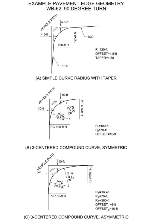
Figure 13-16: Example of Pavement Edge Geometry
Urban Intersections -
Corner radii at intersections on arterial streets should satisfy the requirements of the drivers using them to the extent practical and in consideration of the amount of ROW available, the angle of the intersection, numbers of and space for pedestrians, width, and number of lanes on the intersecting streets, and amounts of speed reductions. The following summary is offered as a guide:The radii dimensions are for simple curves and should be used as supplemental when designing. The radii should be built to accommodate the design vehicle based on the turning movements.
- Radii of 15-ft to 25-ft are adequate for passenger vehicles. These radii may be provided at minor cross streets where there is little occasion for trucks to turn or at major intersections where there are parking lanes. Where the street has sufficient capacity to retain the curb lane as a parking lane for the foreseeable future, parking should be restricted for appropriate distances from the crossing;
- Radii of 25-ft or more at minor cross streets should be provided on new construction and on reconstruction where space permits;
- Radii of 30-ft or more at major cross streets should be provided where feasible so that an occasional truck can turn without too much encroachment;
- Radii of 40-ft or more, and preferably 3- centered compound curves or simple curves with tapers to fit the paths of appropriate design vehicles, should be provided where large truck combinations and buses turn frequently. Larger radii are also desirable where speed reductions would cause problems;
- Radii of 75-ft or more should only be provided for arterial-arterial urban intersections if frequent use of a WB-62 or larger design vehicle is anticipated. A compound curve or simple curve with taper should be used to minimize an intersection footprint; and
- Radii dimensions should be coordinated with crosswalk distances or special designs to make crosswalks safe for all pedestrians.
Where other types of truck combinations are used as the design vehicle, pavement edge geometry as shown in
and
permits the use of lesser radii. An operational measure that appears promising is to provide guidance in the form of edge lines to accommodate the turning paths of passenger cars while providing sufficient paved area beyond the edge lines to accommodate the turning path of an occasional large vehicle.
Rural Intersections –
In rural areas, space is generally more available and speeds are higher. These factors suggest more liberal designs for truck turning even when the frequency of long vehicles may not be as great as in urban areas.In the design of highway intersections with other (non-highway system) public roads, long vehicles are generally infrequent users. Minimally, the SU, or on some occasions the WB–40, design vehicle is appropriate for use unless special circumstances (location of a truck stop or terminal) influence the frequency of use by certain vehicle classes.
For arterial intersections with collectors, the WB-40 design vehicle is generally appropriate, and the WB-62 should be used where specific circumstances warrant.
For arterial-arterial intersections, use by the WB-62 or larger design vehicle should be anticipated within project life. For turning roadway widths to be reasonable, a design radius of 75-ft or more is required. Where circumstances at a particular rural arterial-arterial intersection precludes the use of the WB-62 or larger design vehicle, the WB-40 may be used. Refer to
for radii information with respect to the design vehicle.
Median U-Turn Movements –
In some instances, median openings can be used to facilitate U-turns.
provides minimum median widths “M” (ft) to complete a U-turn movement. For instances where the U-turn can’t be completed, a loon may be used to provide additional space. See
for additional information on loon design.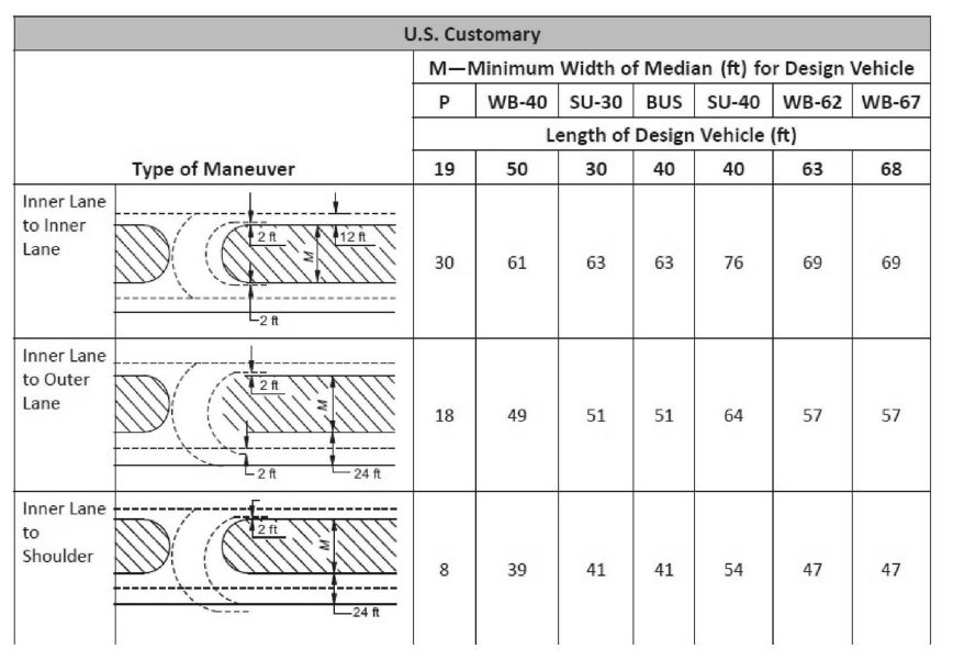
Figure 13-17: Minimum Median Widths For U-Turn Crossovers
Source: FHWA MUT Informational Guide – Exhibit 7-12