4.3 Geometric Alternatives Analysis
The process of identifying and evaluating different geometric elements to determine the best option to satisfy a project’s goals and objectives is accomplished through an alternatives analysis. Geometric alignments, typical sections and intersection types are the major engineering variables to evaluate along with any needed ROW, utility and environmental impacts.
The results of the geometric alternatives analysis may conclude in the preparation of a
geometric schematic
or a geometric layout
.A
geometric schematic
, review and approval process is required for projects that are a:- New location project;
- Added capacity project (including frontage roads);
- Reconstruction with added ROW;
- Interstate ramp relocation project;
- Other improvements that would require an IAJR; or
- Environmental Impact Statement project.
For other project types, a
geometric layout
(see
) may be developed at the District’s discretion.4.3.1 Multiple Route Concepts
For a geometric design, several route concepts may be prepared for evaluation and public input. Routes should be defined enough to determine basic requirements such as initial locations of bridge structures, ROW, business or home relocations, major utility conflicts, and connection to existing cross streets. Routes should be designed to fit constraints that were identified in previous sections.
Horizontal alignments may or may not be developed for ramps, crossroads and interchanges at this stage, however, if they are, ensure that design controls are satisfied. Vertical alignments may be designed at this time as well, especially for the mainlanes, to evaluate project impacts, but are typically not required at this high-level evaluation stage.
illustrates an example of multiple route alignments to be considered.
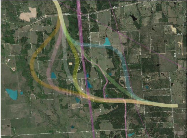
Figure 4-2: Example of Multiple Route Alignments for Consideration
4.3.1.1 Develop Existing and Proposed Conceptual Typical Sections
Typical sections are developed to determine the cross sectional elements of the existing and proposed roadways. Multiple typical sections may be developed as part of selecting route alternatives. Design criteria for features shown on typical sections can be found in the RDM.
Conceptual typical sections typically include:
- Number and type of lanes (determined by calculating traffic volumes for the desired LOS);
- Mainlane and shoulder width;
- Bicycle and pedestrian accommodations width;
- Type and range of median width;
- Possible frontage roads; and
- Range of offset to ROW limits (e.g., side slopes, ditch/curb and gutter, etc.).
Details such as cross slopes, pavement structure and station limits are typically not needed to define a particular route during the conceptual stage.
4.3.1.2 Identify High-Level Environmental Constraints
A high-level environmental constraints map is developed to guide the design of conceptual routes. Environmental technical studies will not begin until a recommended alternative is selected, however, high level environmental constraints can be identified using public databases. Some of these constraints include:
- Floodplains, streams and wetlands;
- Historic structures;
- Schools;
- Cemeteries;
- Parks and recreation areas;
- Culturally significant areas;
- Wildlife habitats; and
- Community boundaries.
Determine the location of as many of these types of constraints as possible to help design and evaluate the route concepts.
4.3.1.3 Conceptual Route Layouts
Conceptual route layouts are prepared to clearly indicate the alternatives to be considered by the pubic and should be easily understood by stakeholders outside of TxDOT (i.e., layouts do not contain detailed engineering information). Alignment alternatives can be narrowed down at this point to present the most reasonable choices to the public for feedback – presenting too many options can cause confusion and make the selection process unmanageable.
Screening criteria for this evaluation may include but are not limited to:
- Alignments to avoid existing homes or displacements;
- Alignments to avoid dividing properties;
- Alignments to avoid railroads;
- Alignments to avoid oil or gas lines/wells;
- Alignments to avoid known cemeteries, grave sites, schools or churches;
- Alignments to avoid potential hazardous material sites;
- Alignments to avoid public park lands;
- Alignments to avoid designated critical habitat and protected species;
- Alignments to avoid impacts to water features and wetlands; and
- Alignments to reduce impacts to floodplains.
Some best practices for preparing
“public friendly”
conceptual route layouts include:- Ensure that a clear and easily understandable naming convention is established for the alternatives to avoid stakeholder confusion (e.g., Blue Route, Purple Route, Yellow Route, or Alt A, Alt B, Alt C);
- Prepare a base map for the layout’s plan view showing existing topographic features. The base map is not necessarily created from detailed field survey data – use aerial imagery if available;
- Add existing ROW limits, locations of major utilities, etc.;
- Add constraints such as proximity to historic structures, hazardous and petroleum materials, threatened and endangered species, national forest boundaries, known water features and wetlands, floodplain boundaries, etc. (refer to TxDOT’s Open Data Portal, TxGIO – formerly TNRIS data hub, and other online sources to gather information);
- Add typical sections to layout;
- Include property owner information;
- Show significant impacts to existing municipality facilities which may include, but are not limited to, water towers, transmission lines, or police/fire stations;
- Show locations of churches, cemeteries and schools with easily identifiable icons;
- Show significant utility conflicts. Add labels to layouts and identify potential utility conflicts;
- Make the schematic as uncluttered as possible; and
- Use enlarged drawings to show areas of a project having significant amounts of detail.
Consult with TPP - Public Involvement Section for additional ideas and/or feedback.
4.3.1.4 Route Alternatives Cost Estimates
Construction and ROW cost estimates are developed to assist in the evaluation of alternatives. The planning level estimate should be updated for each alternative. Use TxDOT’s Construction Cost Estimating Guidance (CCEG) and CCEG spreadsheet tool to develop the conceptual construction cost estimate for each alternative (see
). Include costs for risk contingencies such as potential environmental mitigation, contamination, unknown geotechnical issues or other project unknowns.
Preliminary ROW costs should be calculated according to guidance in
TxDOT’s ROW Appraisal and Review Manual
and the ROW Acquisition Manual
. For additional discussion on developing ROW costs see
.If funding authorization involves federal funds and the preliminary estimates indicate the total project cost may approach the threshold for a Value Engineering analysis (see Section 4.5), contact the DES to discuss options.
4.3.1.5 Public Meetings for Route Concepts
Public meetings provide an opportunity for the public to engage in a free exchange of views and ideas and to share individual concerns. They are an effective method of obtaining public support for a project and may help avoid controversial public hearings (see
) later in project development. A public meeting is held to exchange ideas and collect input on the need for possible changes to design features, alternatives to, and potential impacts of, in addition to mitigation for, a proposed project.
Public meetings are intended to gather input from the public and to keep the public informed during any phase of a project. Public meetings encourage public involvement in the decision-making process, assisting the project team to have a better understanding of needs and concerns within the project area.
Coordinate any type of public involvement with the District Environmental Coordinator prior to any meeting and/or contact with project stakeholders.
A public meeting can be held at any stage of project planning and development.
Public meetings occur as early as TxDOT determines it is feasible to provide an opportunity for public input in project planning, location, design alternatives, and potential mitigation. Public meetings are recommended for projects that require large amounts of ROW, projects that propose access changes, or projects where displacements, impacts to historic properties, substantial public interest, or substantial public controversy are anticipated.There are many options for effectively engaging the public in addition to the traditional public meeting, and many strategic approaches for promoting a required public meeting. Consult with TPP – Public Involvement Section and TxDOT’s statewide Strategic Public Engagement Guidance to develop.
The geometric schematic used for public viewing should be easily understood by the public. See the Schematic QC Checklist for items to include on the public meeting geometric schematic.
See
for more information on conducting public meetings.
4.3.1.6 Route Alternatives Analysis
An alternatives analysis is a decision-making process where multiple route alternatives are evaluated and a recommended route or alignment is selected. The evaluation process developed for selecting recommended routes and alignments is typically based on criteria addressing the project’s purpose and need, project goals and objectives (such as safety and operational improvements), environmental impacts, affected property owners, project cost and stakeholder input.
The level of alternatives analysis is dependent on the rigor of the project including the level and types of environmental impacts. If NEPA is involved or is intended to be involved in the future such as in the creation of an Environmental Impact Statement (EIS) or an Environmental Assessment (EA) then the NEPA guidance for alternative analysis must be followed. See
for detailed information on types of NEPA documents and required alternative analysis procedures.
Refer to the TSAP for more discussion on performing alternative analysis and documentation of analysis results.
Alternatives analysis must
clearly demonstrate minimization and avoidance of impacts
to indicate the selected alternative is the least environmentally damaging alternative.An objective alternative analysis process is necessary to compare the project alternatives so the options can be reduced to a final set or to a single preferred alternative.
illustrates the overall evaluation process.
A separate alternatives analysis is required for historic bridges. Refer to TxDOT’s
Bridge Project Development Manual
for additional information on performing an alternatives analysis for a historic bridge.Some evaluation criteria may be less relevant than others in the decision-making process. Therefore, it is important that each element is weighted if a matrix/numerical analysis is performed (i.e., some categories might be weighted differently if they are important to the adjacent community/project area).
Quality, organization, documentation and presentation of data are critical to the success and credibility of the evaluation and selection process. Thorough analysis of alternatives supports a well-defined scope and minimizes scope creep and incremental cost effects later.
An alternatives matrix and associated narrative is developed to document and present the results of the alternatives analysis (refer to TxDOT’s TSAP).
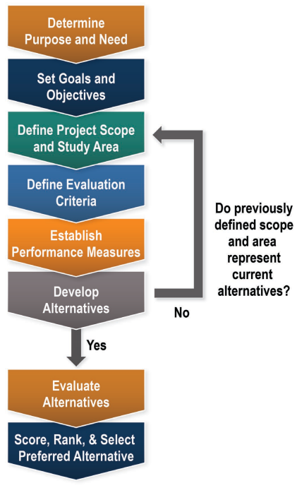
Figure 4-3: Alternative Analysis Process
depicts a Quantitative Evaluation Matrix example and
depicts a Qualitative Evaluation Matrix example that can be used to document the results.
Each project will have different criterion of evaluation based on its unique objectives and needs
. The project team collaborates to determine what criterion is chosen to evaluate.Criterion Type | Criterion | Unit | Alternatives | |||
No Build | Extend Widening | Couplet | Bypass | |||
Safety | Predicted crash frequency | Crashes per Year | 60 | 60 | 50 | 40 |
Net Present Value (NPV) of crash savings | Dollars | $- | $- | $10,000,000 | $20,000,000 | |
Mobility | LOS - Intersection 1 | Grade | C | B | F | C |
Delay - Intersection 1 | sec/veh | 25 | 18 | 87 | 21 | |
LOS - Intersection 2 | Grade | B | B | D | C | |
Delay - Intersection 2 | sec/veh | 14 | 10 | 51 | 26 | |
Access | Bicycle lane-miles | Miles | - | 3 | 6 | - |
Transit lane-miles | Miles | - | 3 | 6 | 8 | |
Other | Proposed ROW Acquisition (Actual) | Square Feet | 105,037 | 105,037 | 91,016 | 121,489 |
*Residential Parcels Impacted | Number | 19 | 19 | 25 | 104 | |
*Commercial Parcels Impacted | Number | - | - | 1 | - | |
Cost | Dollars | $1,000,000 | $8,000,000 | $12,000,000 | $15,000,000 | |
*Impacted is defined as parcels with ROW is impacted by the alternative design
Criterion | Measures | Alternative with *Rating (1-5) | |||||||
Build | Extend Widening to Third Street | One-Way Couple | Two-Lane Elevated Bypass | ||||||
Safety | Conflict points and driver expectancy | 2 | Merge, no access management | 4 | No merge, installed access manageme nt | 4 | Two-to-one-way conversion, introducing uncommon operation, fewer conflict points at intersections | 2 | High speeds, introducing uncommon operation |
Mobility | Travel speed, roadway capacity, and intersection capacity (Delay and LOS | 1 | No increased capacity | 3 | Increased capacity | 4 | Increased capacity, fewer phases at traffic signals | 5 | Increased capacity |
Access | Property entry/exit points and local route distance | 4 | No access management | 3 | Restricted access (raised median) | 2 | Limits access, increases trip distance | 1 | Access controlled |
Property Impacts | Environmental and historic impacts | 5 | No ROW necessary | 3 | 50-foot ROW necessary | 5 | No ROW necessary | 1 | 100-foot ROW necessary |
ROW Cost | Cost of ROW expected to be purchased | 5 | No ROW necessary | 3 | 50-foot ROW necessary | 5 | No ROW necessary | 1 | 100-foot ROW necessary |
Construction Cost | Cost of materials to construct improvements | 5 | No improvement | 3 | Widening Main Street | 3 | Reconstructing Main Street, widening Washington Avenue | 1 | Elevated structure, widening Main Street |
Development Potential | Potential economic benefits | 2 | None | 3 | Increased volume | 5 | ROW made available for social/aesthetic improvements | 1 | None |
*Rating scale is from 1-5. 1 signifies the best rating and 5 signifies the worst rating
4.3.1.7 Preferred Route Selection
The project team selects a preferred route using input from stakeholders, planning partners and detailed information about potential impacts as evaluated using the process described in
. The preferred route provides a solution consistent with the purpose and need for the project. Selection of the preferred route considers and implements previously provided stakeholder input.
The selection of the preferred route is documented based on the requirements of District policy and in coordination with the ENV and the District Environmental Coordinator.
4.3.2 Multiple Alternatives along the Preferred Route
Once the preferred route is selected, the design is optimized by evaluating alternate typical sections, horizontal and vertical alignments and intersections.
The principles of Performance Based Practical Design (PBPD) as described in the RDM should be used to ensure that the design alternatives considered meet the project’s goals and objectives and related criteria that were established during project scoping.
This is an iterative process and may result in one or more alternatives to present to the public to obtain stakeholder feedback.
4.3.2.1 Roadway Typical Section and Alignment Alternatives Refinement
Roadway typical sections should be optimized, and horizontal and vertical alignments more fully developed to determine the best alignment for the project. Some options that are typically considered in this refinement include:
- Roadway typical sections:
- Different lane and shoulder widths;
- Use of medians (depressed, flush, or raised);
- Sidewalks and ADA ramps; and
- Bicycle accommodations, etc.
- Alignments:
- Shifting alignments to one side of the road or the other (e.g., eastern alignment vs. western alignment);
- Using the existing alignment of the road;
- Using a combination of existing alignment and alignment shifts;
- Vertical clearances for structures; and
- Sight distance requirements
4.3.2.2 Intersection Control Evaluation
It is important to perform Intersection Control Evaluation (ICE) at this stage in project development to determine the intersection type that best increases safety and operations. The ICE process is typically used in evaluating the intersection traffic and geometric control at new or modified intersections.
ICE provides a framework of quantifiable measures to evaluate alternatives so that public agencies, engineers, and planners make enhanced and more informed decisions. Quantitative measures are considered alongside qualitative measures such as multimodal needs and community vision goals to provide a well-rounded perspective when selecting the preferred alternative.
Refer to TxDOT’s TSAP for guidance on performing a Stage 1 and Stage 2 ICE analysis. Similar to typical sections and alignments, the intersection controls need to consider cost, ROW, environmental impacts, utility impacts, etc. as part of the intersection type determination.
illustrates the ICE Stage 1 and Stage 2 workflows.
Refer to the ICE directive published by DES.
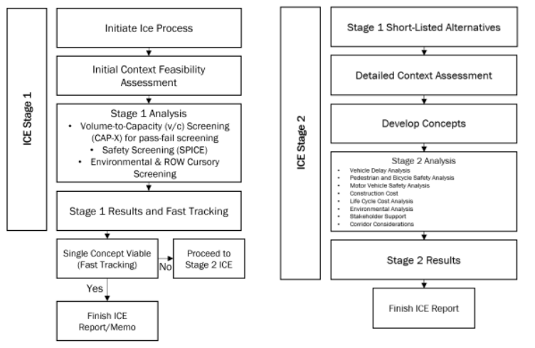
Figure 4-4: ICE Stage 1 and Stage 2 Workflows
4.3.2.3 Potential ROW Needs, Utility Conflicts and Environmental Impacts Identification
For each alternate developed for evaluation, the amount of potential ROW needed, utility conflicts and obvious environmental impacts are identified along with any “fatal flaw” elements that may eliminate an alternative (e.g., high-pressure gas line along one side of the roadway, cemetery or historical structure).
4.3.2.4 Alternative Alignment Layouts Development
If needed, alternate alignment layouts are developed for each alternative for review by the District and presentation to the public to obtain stakeholder feedback.
If the layouts are being prepared for public display, they should be developed similarly to the conceptual route layouts described in
– the layouts should be easily understood by the public. Additional details such as proposed ROW, locations of ramps, control of access, dedicated bike/ped facilities, dedicated transit facilities, retaining wall locations, bridge structures, driveways, existing utilities and intersection types are shown on the layouts at this stage.
4.3.2.5 Alignment Alternatives Cost Estimates
Construction and ROW cost estimates are developed for each of the alignment alternatives to assist in the evaluation and selection of a preferred alignment. Update the planning level estimate for each alternative using TxDOT’s CCEG and CCEG spreadsheet tool (see
).
If funding authorization involves federal funds and the preliminary estimates indicate the total project cost may approach the threshold for a VE Analysis (see
), contact the DES to discuss options.
4.3.2.6 Public Meetings for Alignment Alternatives
If desired, a public meeting can be conducted to obtain additional input from stakeholders on the alignment alternatives. The public meeting should be organized and conducted similarly to the conceptual layout public meeting described in
.
There are many options for engaging the public beyond, or in addition to, a public meeting. There are also many effective ways to promote public engagement opportunities. Consult with TPP – Public Involvement Section for assistance.
If the project is going through the NEPA process (see
), coordinate all public involvement with the District Environmental Coordinator to ensure that all engagement with the public is documented correctly and included in the environmental document.
4.3.2.7 Alignment Alternatives Analysis
Each alignment alternative is evaluated based on scoring criteria as determined by the project’s purpose and need and goals and objectives. Evaluation of alignment alternatives typically involves more detailed analysis and determination of project level impacts.
The project team along with appropriate SMEs determine the scoring criteria to be used for evaluation of the alternatives and any associated weighting of criteria. Commonly used scoring criteria of multiple alignments includes:
- Safety;
- Mobility;
- Access;
- ROW costs;
- Utility impacts;
- Environmental impacts;
- Funding; and
- Project specific objectives.
The alignment alternatives analysis is documented as described in
and coordinated with the District Environmental Coordinator.
depicts an alternatives analysis matrix used to compare different alignments within different route segments.
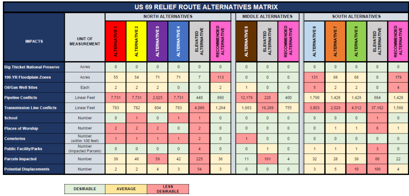
Figure 4-5: Example of Alignment Alternatives Analysis Matrix
4.3.2.8 Recommended Alternative Selection
Once the alternatives are independently evaluated, analyzed and documented, the recommended alternative is selected and is used to develop the geometric schematic for final approval.
|
|
|
|
|