Free Surface at Outlet and Full Flow at Inlet (Type AB)
When the outlet is not submerged, full flow will begin within the conduit if the culvert is long enough and the flow high enough. Figure 8‑12 illustrates this condition. This condition is possible if the theoretical value of uniform depth is higher than the barrel depth. The following steps should be followed:
- Check Type AB uniform depth. Compare calculated uniform depth and the barrel depth, D. If the theoretical value of uniform depth is equal to or higher than the barrel depth, proceed to Free Surface Losses. Otherwise, refer to .
- Determine Type AB free surface losses, if applicable. Refer to Water Surface Profile Calculations, Free Surface Flow to determine the water surface profile in the conduit. If the computed depth of flow reaches or exceeds the barrel depth before the end of the conduit, note the position along the conduit at which this occurs and proceed to full flow losses below. Otherwise, complete the procedure described under Free Surface Flow.
- Determine Type AB full flow losses, if applicable. Begin full flow calculations at the point along the conduit where the computed water surface intersects the soffit of the barrel as determined above. Determine the energy losses through the remainder of the conduit using Equation 8-11 but substituting Lf, the remaining conduit length, for L.
- Determine Type AB hydraulic grade line at inlet, if applicable. Compute the depth of the hydraulic grade line, Hi, at the inside of the inlet end of the conduit using Equation 8-12. Use the barrel height D as the starting hydraulic grade line depth in place of Ho,and use the remaining length, Lf, in place of L. Refer to Energy Balance at Inlet to determine headwater depth.
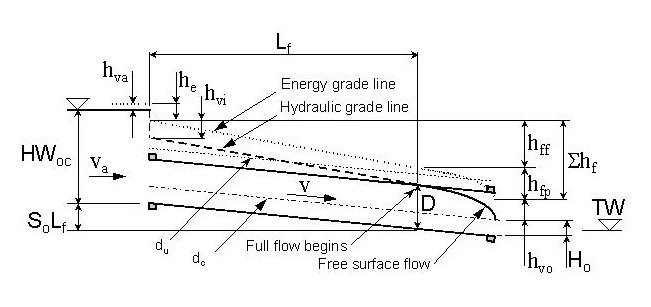 Figure 8-12. Headwater Due to Full Flow at Inlet and Free Surface at Outlet