Section 3: Delineators and Chevrons
Introduction
Road delineators and chevrons are retroreflective
devices mounted near the edge of a roadway to indicate the roadway
alignment. They are typically used when changes in horizontal
alignment or pavement width transitions exist. They are
effective aids for night driving and when either rain or snow limits
the effectiveness of pavement markings.
Delineator Design (Texas MUTCD, Section 3F.02)
Delineators consist of retroreflective material with a minimum dimension of 3 inches. Figure 8-4 indicates various delineator designs.

Figure 8-4. Delineators
Delineator and Object Marker Application and Spacing (Texas MUTCD, Section 3F.04)
Table 8-1 indicates the various uses for delineators for different types of roadways and roadway situations.
DELINEATOR AND OBJECT MARKER APPLICATION AND SPACING | ||
|---|---|---|
Condition | Required Treatment | Minimum Spacing |
Frwy./Exp. Tangent | RPMs | See PM-series and FPM-series standard sheets |
Frwy./Exp. Curve 1 | Single delineators on right side | See Tables 8-3 and 8-4 |
Frwy./Exp. Ramp | Single delineators on at least one side of ramp (should be on outside of curves) (see Fig.8-22) | 100 feet on ramp tangents. Use Tables 8-3 and 8-4 for ramp curves (“straightaway spacing” does not apply to ramp curves) |
Acceleration/Deceleration Lane | Double delineators (see Fig. 8-22) | 100 feet (see Fig. 8-22) |
Truck Escape Ramp | Single red delineators on both sides | 50 feet |
Bridge Rail (steel or concrete) and Metal Beam Guard Fence | Bi-directional delineators when undivided with one lane each direction Single delineators when multiple lanes each direction | Equal spacing (100’ max) but not less than 3 delineators |
Guard Rail Terminus/Impact Head | Divided highway-Object marker on approach end Undivided 2-lane highways - Object Marker on approach and departure end | Requires Type 3 Object Marker or reflective sheeting provided by manufacturer |
Bridges with no Approach Rail | Type 3 Object Marker at end of rail and 3 single delineators approaching rail | See Fig. 8-18 |
Reduced Width Approaches to Bridge Rail | Type 2 Object Markers and 3 single delineators approaching bridge | See Fig. 8-17 |
Culverts without MBGF | Type 2 Object Markers | See Fig. 8-21 |
Crossovers | Double yellow delineators or RPMs | See Figures 8-11 and 8-12 |
Pavement Narrowing (lane merge) on Freeways/Expressway | Single delineators adjacent to affected lane for full length of transition | 100 feet |
1
Delineators are not required in urban areas with continuous lighting. Use of Delineators and Chevrons in Curves
When determining if or whether delineators or chevrons are needed in curves, the posted speed limit and advisory speed limit for the curve are used. Table 8-2 shows the recommended devices to be used based upon the difference between the posted speed and advisory speed.
USE OF WARNING DEVICES AT CURVES WITH ADVISORY SPEED LIMITS | |
|---|---|
Amount by Which Advisory Speed is Less Than Posted Speed | Warning Devices Needed |
5 MPH & 10 MPH | RPMs |
15 MPH & 20 MPH | RPMs, Delineators and Large Arrow (W1-6) or RPMs and Chevrons |
25 MPH & Greater | RPMs and Chevrons |
Figures 8-6 through 8-8 illustrate the three scenarios shown in Table 8-2 for two-lane two-way roadways. In each figure, all required markings and signing are shown, as well as any optional signing. A W1-1 right angle curve or W1-2 curve warning sign is placed on the approach with the appropriate advisory speed plaque in each scenario. A supplementary W1-1a or W1-2a sign may also be installed at the beginning of the curve, but may not be used in place of the approach W1-1 or W1-2 sign. Any curve with an advisory speed of 30 mph or less requires the use of the W1-1 sign instead of the W1-2 sign. Other curve signs may be used depending on roadway geometries.

Figure 8-5. Curve Signs and Chevrons
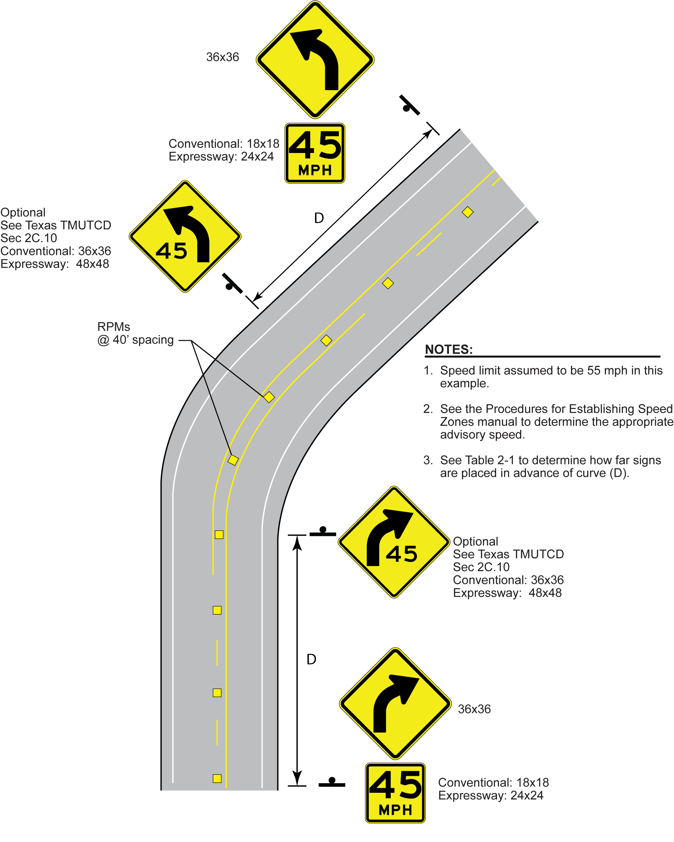
Figure 8-6. Curve Treatments when Advisory Speed is 5-10 mph Below Posted Speed
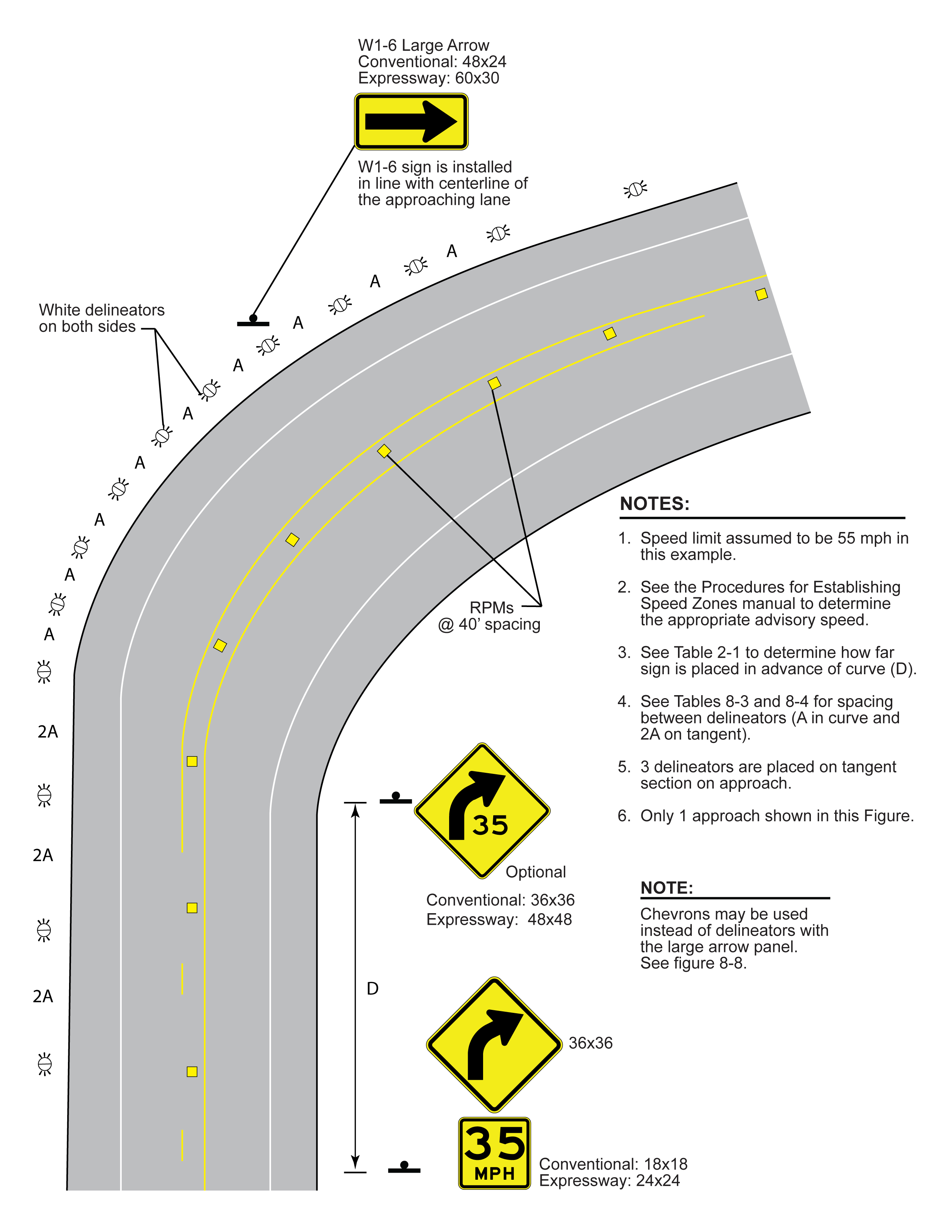
Figure 8-7. Curve Treatments when Advisory Speed is 15-20 mph Below Posted Speed
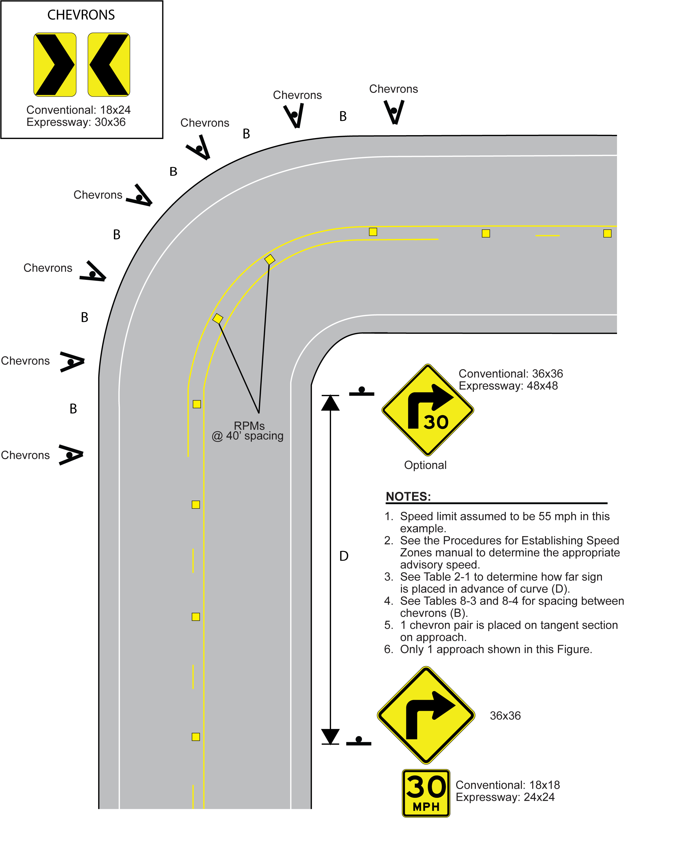
Figure 8-8. Curve Treatments when Advisory Speed is 25 mph or More Below Posted Speed
Delineator Placement
Typically, the height of delineators is approximately 4 ft above the near edge of the pavement to the bottom of the lowest retroreflective device. Delineators are located 2-8 ft from the edge of the pavement. All delineators on a stretch of highway should be the same distance from the edge of the pavement, except where a restriction exists (such as guardrail, culvert headway, or other obstruction). Where a restriction exists, the delineators should be in line with the inner most edge of the obstruction. Figure 8-9 depicts typical delineator placement.

Figure 8-9. Typical Delineator Installation
When delineators are installed further than 8 ft from the edge of the pavement, it may not be practical to provide a height of 4 ft. In this case, the delineator is installed so the reflective unit is as close to 4 ft above the surface of the pavement edge as practical.
Delineators may be attached to a vertical support. An example includes along guardrail posts or cable barrier. Figure 8-10 illustrates examples of delineators attached to guardrail posts.
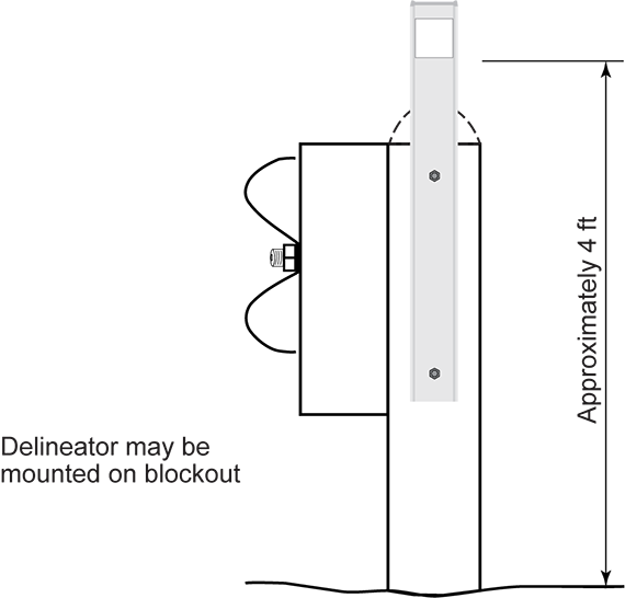
Figure 8-10. Delineator Installation on Guardrail Post
Chevron Placement
Chevrons are placed the same distance from the edge
of the traveled lane and pavement as other signs as shown in Chapter
4. They may be placed at a height of either 7.0 - 7.5 ft (with triangular
slip base) or 4.0 - 4.5 ft (with wedge anchor and when size of chevron is
24" x 30" or smaller, such that height from ground to top of chevron
does not exceed 6'6") measured from the edge of traveled lane to
bottom of the chevron as shown in Figure 4-22.
Delineator and Chevron Spacing
Spacing for delineators and chevrons depends on the application. However, when a driveway or intersection interrupts the selected spacing interval, the delineator or chevron should be located as close to its correct position without interfering with the driveway or intersection.
- Horizontal Curves -On horizontal curves, spacing should be adjusted so that several delineators or chevrons are always visible to the driver. Tables 8-3 and 8-4 illustrate spacing for delineators and chevrons on horizontal curves as well as on approaches and departures from horizontal curves.
- Roadside Barriers -When delineators are used in conjunction with roadside barriers (i.e., guardrail or bridge rail) on straight sections of roadway, the spacing should be adjusted to ensure a minimum of three delineators are used, with a maximum spacing of 100 ft between any two delineators. When the roadside barrier is located along a curved section, Table8-3 or 8-4should be used to determine the appropriate delineator spacing up to a maximum of 100 ft. Section 4 should be used for applications concerning concrete median barriers.
Other types of retroreflective devices may be used on sections of roadways with guardrail, bridge rail, or concrete barrier. See Section 4 for more information.
DEGREE OF CURVE | RADIUS OF CURVE, FT | DELINEATOR SPACING IN CURVE (A), FT | DELINEATOR SPACING IN STRAIGHTAWAY (2A), FT | CHEVRON SPACING IN CURVE (B), FT |
|---|---|---|---|---|
1 | 5730 | 225 | 450 | = |
2 | 2865 | 160 | 320 | = |
3 | 1910 | 130 | 260 | 200 |
4 | 1433 | 110 | 220 | 160 |
5 | 1146 | 100 | 200 | 160 |
6 | 955 | 90 | 180 | 160 |
7 | 819 | 85 | 170 | 160 |
8 | 716 | 75 | 150 | 160 |
9 | 637 | 75 | 150 | 120 |
10 | 573 | 70 | 140 | 120 |
11 | 521 | 65 | 130 | 120 |
12 | 478 | 60 | 120 | 120 |
13 | 441 | 60 | 120 | 120 |
14 | 409 | 55 | 110 | 80 |
15 | 382 | 55 | 110 | 80 |
16 | 358 | 55 | 110 | 80 |
19 | 302 | 50 | 100 | 80 |
23 | 249 | 40 | 80 | 80 |
29 | 198 | 35 | 70 | 40 |
38 | 151 | 30 | 60 | 30 |
57 | 101 | 20 | 40 | 20 |
ADVISORY SPEED (MPH) | DELINEATOR SPACING IN CURVE (A), FT | DELINEATOR SPACING IN STRAIGHTAWAY (2A), FT | CHEVRON SPACING IN CURVE (B), FT |
|---|---|---|---|
65 | 130 | 260 | 200 |
60 | 110 | 220 | 160 |
55 | 100 | 200 | 160 |
50 | 85 | 170 | 160 |
45 | 75 | 150 | 120 |
40 | 70 | 140 | 120 |
35 | 60 | 120 | 120 |
30 | 55 | 110 | 80 |
25 | 50 | 100 | 80 |
20 | 40 | 80 | 80 |
15 | 35 | 70 | 40 |
Delineation for Divided Highway Intersections and Crossovers
The following delineation is typically used for divided highway intersections and crossovers:
- With left turn bay on approach: Use raised pavement markers (RPMs) to supplement the solid left turn lane line or a double yellow delineator on the opposite median. Figure 8-11 illustrates this application. The RPMs are placed 1 inch inside the left turn lane line and at 10 ft spacing. Use a Type II-C-R RPM. If desired, both the RPMs and double yellow delineator may be used.
- With no left turn bay on approach: Use double yellow delineator on far side of median opening or 4 Type I-A RPMs to supplement lane line on the approach at 20’ spacing. Figure 8-12 illustrates this application. If desired, both the double yellow delineator and RPMs may be used.
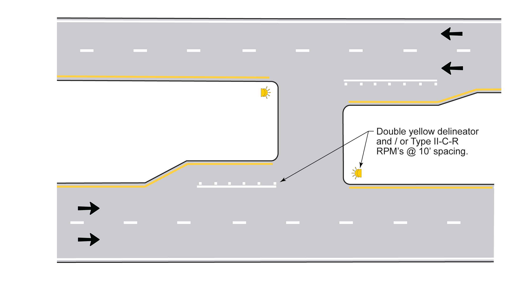
Figure 8-11. Delineation for Median Opening with Left Turn Lane on Approach

Figure 8-12. Delineation for Median Opening with No Left Turn on Approach