Convention Used in Illustrations
The illustrations contained in this chapter utilize several conventions to simplify the information being presented in the figures.
- Use of Highway Classifications and Numbers in Illustrations- The highway intersections illustrated in this field book are not intended to represent specific intersections in the state. For simplicity, only one highway class is used for all highways in the illustrations, and no more than six different route numbers are used. The six highway numbers used in the illustrations are three-digit U.S. Highway numbers: U.S. 180, U.S. 259, U.S. 290, U.S. 281, U.S. 377, and U.S. 380.
- Reference Points for Placement Distances- The distance shown in the figures is the distance between the sign installation and the near edge of the intersecting roadway. Figures 5-2 and 5-3 illustrate the application of this convention, and Table 5-1 contains the placement distances for each type of sign that could be used on an approach to an intersection.
- Cross-References to the Texas MUTCD- Where it is appropriate, notes in the figures refer to material in the Texas MUTCD related to the use of a specific sign. These cross-references are typically provided to help the user determine whether a sign should be used in a particular situation.
- Figure Symbol Boxes Description- Each of the figures shown in Sections 3, 4, and 5 has a symbol box located in the lower right-hand corner of the figure. The purpose of these boxes is to assist in quickly determining what is illustrated in a particular figure. These symbol boxes represent the intersection geometrics, routing arrangement, and type of traffic control devices used in the intersection. Each of these symbol boxes has two basic sections. The left most section contains the type of traffic control device used at the intersection, such as a Stop sign, a traffic signal, or no control. The right most section contains the sketch of the intersection geometry and routing arrangement for the intersection. The arrows in the right section of the box represent the intersection routing arrangement. They show the direction the assigned routes are going or in some cases ending. For example, the symbol box in Figure 5-1 illustrates the following: the left-hand section of the symbol box tells that a Stop sign with Cross Traffic Does Not Stop plaque is used as the traffic control device. Likewise, in the right-hand section of the symbol box, is shown having a routing arrangement that consists of the approach route going left.
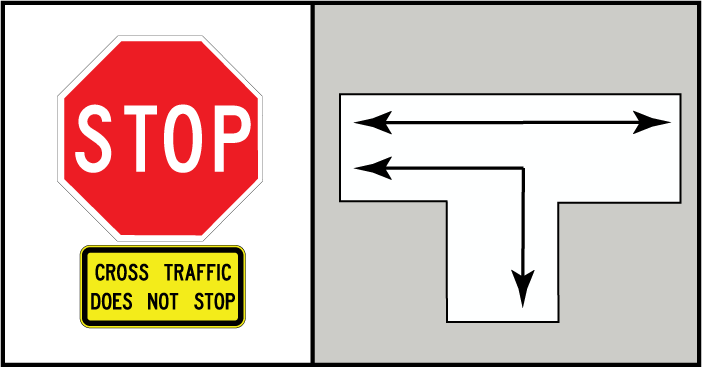
Figure 5-1. Example of Symbol Box
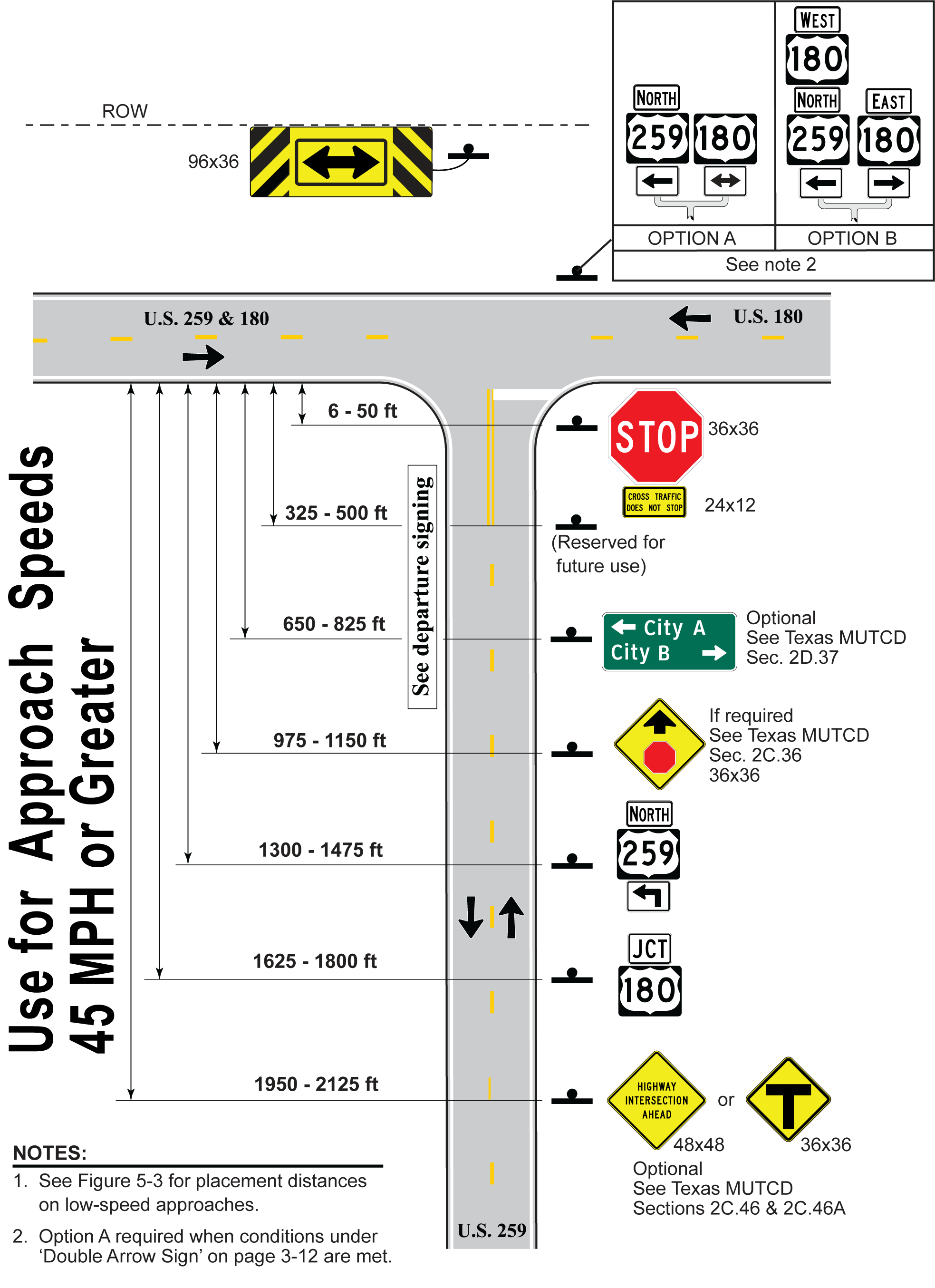
Figure 5-2. Convention for Sign Placement Distances on High-Speed Approach
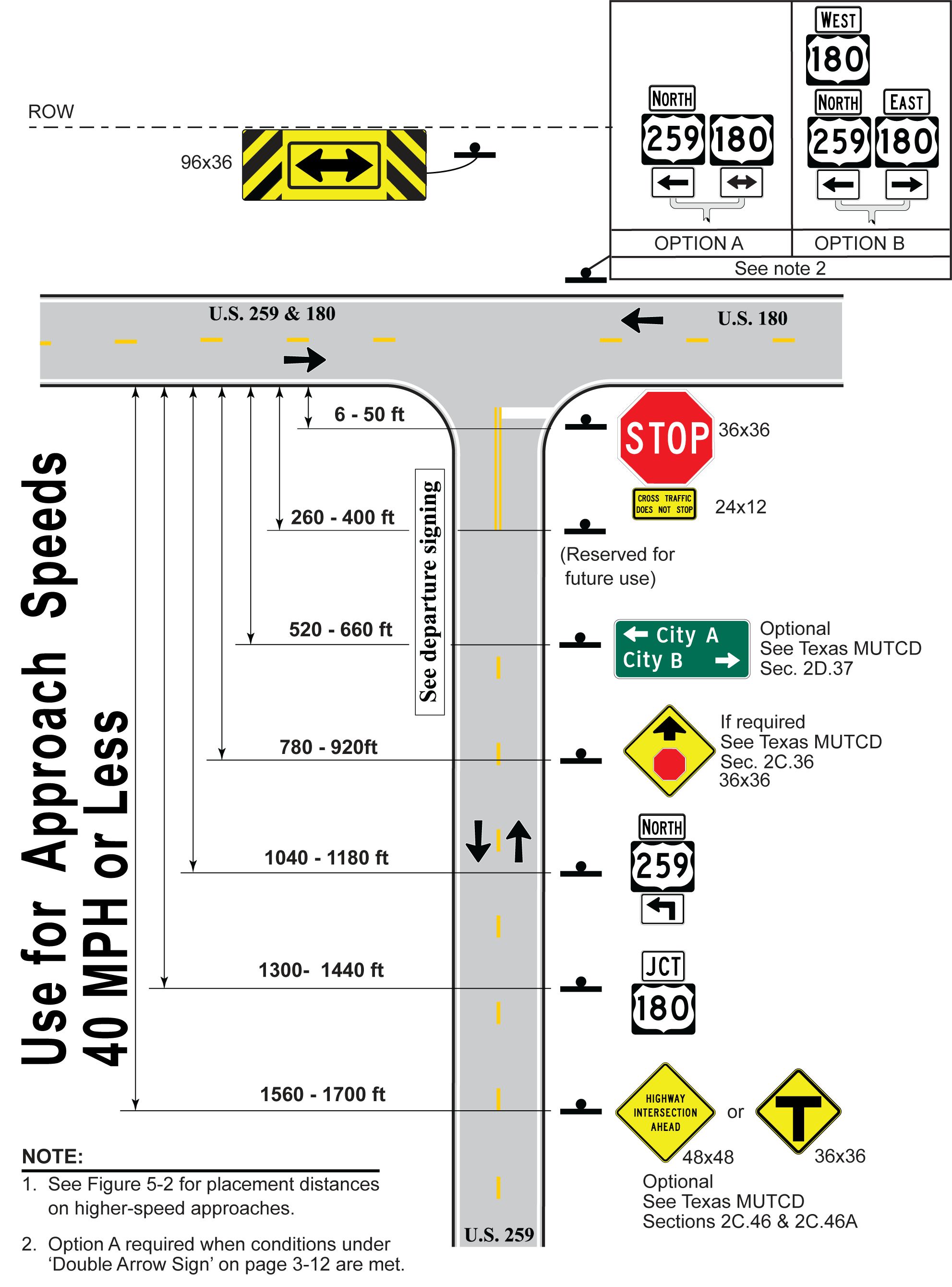
Figure 5-3. Convention for Sign Placement Distances on Low-Speed Approach