Thickness
Inspection of marking thickness is important to ensure that the specified amount of material is being placed on the roadway. Experience has shown that marking thickness is a major factor in the long-term performance of the marking, especially on pavements with surface treatments. Thicker thermoplastic markings on a new surface treatment have been shown to provide better retroreflective performance over time.
Inspection of pavement marking thickness should be performed in accordance with Test Method
“Determining Thickness of Thermoplastic Stripe.” The recommended method of measuring thermoplastic thickness is by mechanical measurement of a sample with a needlepoint micrometer during the striping operation (Figure 3-1).
Measurements should be made to the top of the binder material, excluding the bead. While calipers have been used in the past, they are no longer considered an approved measurement device for measuring the thickness of pavement markings and should not be used. This is because calipers are unable to measure between the beads, creating artificially high measurements.
Samples should be taken from the striping operation using a metal plate or duct tape.
It is absolutely necessary that the duct tape or plate be placed on the pavement surface in a covert manner.
This placement prevents the striping contractor from slowing the truck prior to the tape or plate to create an artificially thicker sample.Sampling should occur at maximum 2,000-foot intervals according to Test Method
. A minimum of three measurements should be taken diagonally across each sample as shown in Figure 3-2. All measurements should meet or exceed the thickness specified in the contract. If measurements are less than the thickness specified in the contract, notify the contractor
immediately
.
Figure 3-1. Needlepoint micrometer measuring thermoplastic sample.
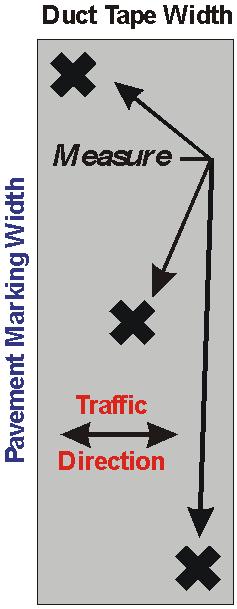
Figure 3-2. Recommended thickness measurement locations.