Queue Cutter Traffic Signals
As the CSD increases, advance preemption times can become very long due to the time required to clear the MTCD and CSD. In cases where the grade crossing is located farther than 400’ from a signalized intersection, an actuated queue cutter traffic signal can provide adequate queue management at the grade crossing. Queue cutter traffic signals are independently-controlled traffic control signals (not operated in conjunction with the traffic control signal faces at a downstream signalized intersection) located at a grade crossing that control traffic in one direction only on the roadway for the purpose of keeping the MTCD clear of vehicles. A queue cutter traffic signal functions by “cutting” the queue upstream of the grade crossing by turning red before vehicles queue onto the railroad tracks. Queue cutter traffic signals should utilize queue detection downstream of the grade crossing to prevent on-track queuing. Generally, any detection type may used to detect the vehicle queue, but vital loop detection should be considered. The Diagnostic Team should discuss detection types and evaluate each grade crossing individually to determine the best solution.
Many design features of a queue cutter traffic signal are similar to a pre-signal as shown in Figure 6-4. The most notable difference is the detection zone which is essential for queue cutter traffic signal operation. Queue cutter traffic signal indications shall comply with Sections 4D.07 and 4D.08 of the TMUTCD. Queue cutter mast arms should be placed downstream of the grade crossing, where possible, as it places the stop line closer to the crossing. A queue cutter may be installed upstream of the grade crossing as necessary to provide the most effective display to approaching motorists as determined by the Diagnostic Team.
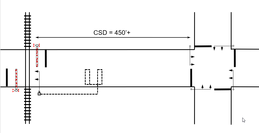
Figure 6–4. Elements of a Queue Cutter Traffic Signal
Queue Cutter Traffic Signal Operations
The queue cutter traffic signal queue detection zone should be located far enough away from the crossing to detect a growing queue, transition the queue cutter traffic signal by serving any minimum green and yellow change interval time, and then allow a design vehicle that has already passed the queue cutter traffic signal’s stop line to clear the MTCD before the queue extends to the grade crossing. Once the queue cutter traffic signal displays a red signal indication, the queue cutter traffic signal shall continue to display a red indication as long as the downstream vehicle detection system continues to detect the presence of stopped vehicles.
Supplemental queue detection zones should be considered when accounting for any turning movements between the grade crossing and the downstream intersection. These detectors should detect the formation of any intermediate queues to activate the queue cutter traffic signal prior to any on-track queuing occurring. Supplemental detection zones could be used to account for different platooning and arrival patterns during different times of the day and/or year.
When the queue cutter traffic signal is displaying a green signal indication and is preempted by the traffic control relay (i.e. advance preemption), the queue cutter traffic signal shall transition to preemption operations by serving any remaining minimum green followed by the yellow change interval and steady red signal indications. If the queue cutter traffic signal is preempted by the crossing active relay (i.e. simultaneous preemption), it shall immediately transition to the yellow change interval and steady red signal indications. The queue cutter shall continue to display red signal indications until the train clears the grade crossing. When there is no active preemption call and no queue is detected by the downstream detection, the queue cutter traffic signal shall finish timing any active minimum red interval, if used, and transition to green signal indications. Queue cutter traffic signal faces shall not display green signal indications when the grade crossing flashing-lights are activated both before the train arrives and after the train leaves the crossing. Figure 6-5 provides an illustration of a queue cutter traffic signal phasing diagram.
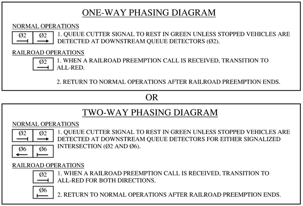
Figure 6–5. Phasing Diagram for a Queue Cutter Traffic Signal
Various types of queue detection may be used. However, the Diagnostic Team should consider the critical nature of the detection zone when recommending a detection type for a queue cutter traffic signal. The failure modes of the queue cutter traffic signal system and the downstream vehicle detection system shall be evaluated and accounted for in the design of any such system. Fail-safe design techniques shall be used in the system design, such as health monitoring and self-check operation to validate the proper functioning of the system. If the detector system fails to properly monitor its health status, then the queue cutter traffic signal shall display flashing red indications until the issue is resolved and the system functions normally.
Placement of downstream detection is key to effective operation of a queue cutter traffic signal and can be an iterative process. Placement should be measured relative to the far limit of the MTCD (i.e. 6 feet from far rail) at a distance equal to the time to detect stopped vehicles (T) plus the yellow change interval (Y), based on the 85th percentile speed. The time, T, should be based on field observations, but is typically around 4 seconds. Yellow time shall comply with TxDOT timing standards. The designer should conduct field observations of queue buildup times during the peak periods. If the observed queue buildup times are significantly less than the time required to transition the queue cutter traffic signal to red than a hybrid queue cutter/pre-signal operation should be used.
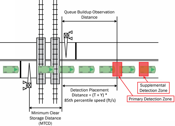
Figure 6–6. Detection Placement for Queue Cutter Traffic Signals