Pre-Signals
A pre-signal has traffic control signal faces that are located upstream from a signalized intersection and are operated in conjunction with the traffic control signal faces at the downstream signalized intersection in a manner that is designed to keep the area between the stop line for the upstream traffic control signal faces and the stop line for the downstream signalized intersection clear of queued vehicles. When used in conjunction with a grade crossing, the pre-signal is operated for the purpose of preventing vehicles from queuing within the Minimum Track Clearance Distance. Supplemental near-side traffic control signal faces for the downstream signalized intersection are not considered to be pre-signals.
Pre-signals may be installed when the downstream traffic signal is located relatively close to the grade crossing (less than 200 feet). Figure 6-2 shows the typical layout of a pre-signal installation downstream of the grade crossing.
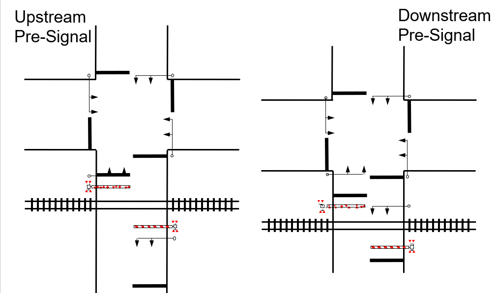
Figure 6-2. Elements of a Pre-Signal
Pre-Signal Operations
A pre-signal’s phase sequencing shall be timed with an offset from the downstream traffic signal such that the pre-signal’s green indication terminates prior to the downstream traffic signal’s green indication in order to reduce the possibility of motorists queuing on the tracks. The distance between the crossing and the downstream intersection can affect motorist behavior. For example, if the clear storage distance (CSD) is long enough, vehicles may be able to safely queue within the CSD without intruding into either the intersection or the grade crossing. In this case, the offset between the pre-signal and the downstream signal may be timed to allow for queuing in the CSD. The pre-signal offset shall always be timed to clear the MTCD after every cycle. The pre-signal offset should be determined based on the time it takes a design vehicle traveling at the posted speed limit to traverse and clear the MTCD and CSD, if needed. The all-red clearance interval for the downstream signal should be determined based on the intersection width but should exclude the MTCD and CSD measurements as the pre-signal’s all-red clearance interval will be long enough to allow vehicles to safely clear the additional distance due to the pre-signal offset.
Pre-signals operate in conjunction with the downstream traffic signal. Pre-signal faces shall display a steady circular red signal indication during railroad preemption to prohibit highway vehicles from entering the grade crossing area. During the Preemption Clearance Interval, the downstream traffic signal shall display the green signal indications for any motorists between the grade crossing and the downstream intersection. Pre-signal indications shall remain red while the grade crossing flashing-lights are activated. Figure 6-3 depicts an example of a pre-signal phasing diagram, with Ø3 and Ø8 as the pre-signal phases.
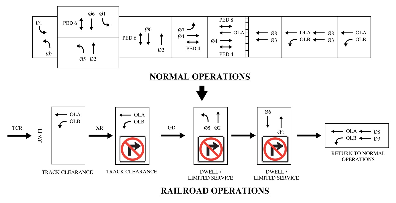
Figure 6–3. Phasing Diagram for a Pre-Signal
Pre-Signal Design Considerations
As shown in Figure 6-2, several design elements should be accounted for when considering a pre-signal installation.
Pre-signals are primary signal faces and shall comply with Sections 4D.07 and 4D.08 of
. Pre-signal mast arms should be placed downstream of the grade crossing. A pre-signal may be installed upstream of the grade crossing as necessary to provide the most effective display to approaching motorists as determined by the Diagnostic Team. An example of where upstream placement may be necessary is when the downstream intersection is located extremely close to the grade crossing. If there is not be enough space for both the intersection’s traffic signal equipment and the pre-signal, the pre-signal may be placed upstream so the proper clearances are met.
Limited visibility signal heads shall be installed at the downstream intersection such that when motorists approach the grade crossing, the pre-signal indications are the only indications visible to encourage motorists to stop upstream of the grade crossing. Motorists who have passed the railroad flashers should be able to fully view the limited visibility signal heads and be encouraged to travel through the grade crossing rather than queue on the railroad tracks. With proper design and good motorist compliance, no motorists will be queued between the grade crossing and the signalized intersection.
The use of stop lines at pre-signal locations may vary depending on the location, but it is important to clearly indicate to motorists an appropriate stopping point. When multiple stop lines are placed – for example, one at the grade crossing, and one at the intersection – it can become confusing for motorists to understand where to stop and may lead to instances where they will queue at risky locations. If the CSD can accommodate the design vehicle, stop lines may be placed at both the grade crossing and the intersection; otherwise, the intersection stop line should be shared with the grade crossing stop line. The stop line located at the grade crossing shall be accompanied by R10-6 sign(s) and supplemental traffic signal heads where possible to emphasize the appropriate stopping point. Signs and traffic signal heads located upstream of the crossing shall not obstruct visibility of any railroad warning device.
Crosswalk placement may also lead to confusing motorist perception of the proper stopping point. Crosswalks should not be placed on the same leg of the intersection as the grade crossing. If a crosswalk is installed adjacent to the grade crossing, a crosswalk design (such as a continental configuration) should be chosen that does not resemble a stop line (such as a standard configuration). Refer to TMUTCD Figure 3C-1 for crosswalk marking options.