Equipment Sheet Requirements
Equipment sheets are specialized Typical Detail sheets that tabulate Cubic Volume for a Broadband Installation. An equipment sheet shall accurately include each of the following that applies:
- Plan View and Profile View, or multiple Profile Views, or combined Plan View and Profile View (isometric) of any visible component with a measurement greater than 6"
- List of external components separately in Typical Detail
- Length, width, and depth in inches or feet and inches for any length greater than 10'
- Manufacturer and model number
- Total cubic feet
Each component shall be identified as an antenna, a Network Node, or ancillary equipment. Each Typical Detail on the equipment sheet shall be numbered and labeled to reference the Typical sheet. The use of borders around details is required. See Figure B-6.
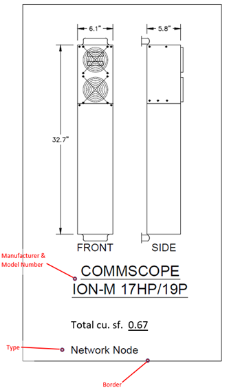
Figure B-6. Sample Typical Detail (Network Node)
In addition to the individual component Typical Detail, each equipment sheet shall include a separate note box that identifies the total Broadband Installation volume, in cubic feet, as shown in Figure B-7. The total cubic feet note shall be in bold type, located in the lower right-hand quadrant of the equipment sheet.
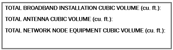
Figure B-7. Sample “Total Cubic Feet” Note
Linework and annotations shall be drafted using computer-aided design software. Scanned or cropped images are not acceptable. Equipment shall be drawn to the scale in the Plan View and Profile View sheets.