Distributor Spray Bar
The spray bar and spray nozzles regulate the amount of asphalt sprayed on the roadway and regulate the spray pattern. Figure 7‑11 shows a typical distributor spray bar.
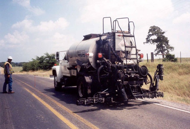
Figure 7-11. Typical Distributor Spray Bar.
The spray bar on most distributors used on seal coat projects is 12 feet wide – the width of a typical traffic lane. Different bar widths are available. Ten to 14-foot widths are recommended.
The bar is composed of a series of spray nozzles evenly spaced (every 4 inches) along the bar. It contains a return line for continuous circulation of asphalt through the bar. Some models are equipped with shut-off valves on each nozzle to allow closing a few spray nozzles for spraying irregular areas. Figure 7‑12 shows the nozzles on a typical spray bar.
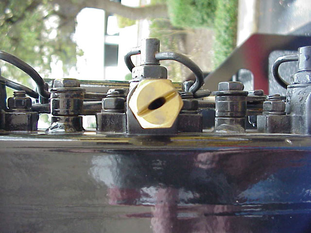
Figure 7-12. Nozzle on Typical Spray Bar.
Hinged Bar.
Most spray bars are hinged at each end to allow the end to be folded up when spraying is not in progress. The distributor should never be driven in traffic with the ends extended, because they extend beyond the sides of the truck. Some have chains attached at the ends of the bar and to the truck chassis. The chains help to support the ends of the bar when they are in the spray position. Chains may also serve as a safety hitch to hold the ends securely in the upright position. Figure 7‑13 shows the spray bar ends folded up.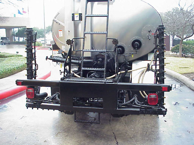
Figure 7-13. Hinged Spray Bar with Ends Folded Up.
Spray Nozzles.
Nozzles are manufactured with different size openings to permit different application rates of asphalt. Nozzles are designed to spray a fan-shaped pattern, rather than a circular spray. Viewed from the top they would look as shown in Figure 7‑14. Viewed from behind the distributor, they would appear as shown in Figure 7‑15. Some distributors are equipped with a second spray bar, sometimes called a wheelpath bar. This second spray bar is used to spray a different application rate in the wheelpath and is controlled with a separate computer.
Figure 7-14. View of Distributor Bar as Seen from Top of Distributor.
Figure 7-15. View of Distributor Bar as Seen from Rear of Distributor.
Inspecting the Spray Bar.
To inspect the spray bar, it should be raised and, if possible, rotated outward so the nozzles can be inspected as shown in Figure 7‑16. The nozzles are critical to obtain uniform asphalt coverage. They must be in good condition and properly oriented to obtain consistent asphalt coverage across the width of the lane being sealed. Nozzles are typically made of brass and can easily be gouged or otherwise damaged, which will affect spray pattern.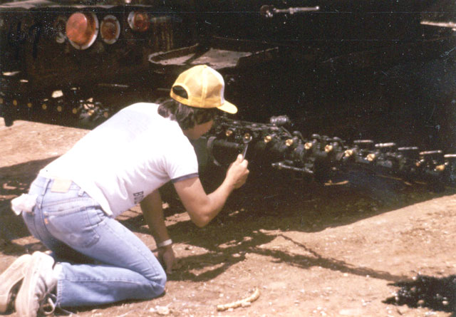
Figure 7-16. Distributor Spray Bar Rotated Outward.
The following is a list of several items on the spray bar that must be inspected.
- Spray Bar Ends. The ends of the bar should be checked to see that they can be raised and lowered. There should be some method of securing the ends in the raised position. Most models are equipped with a chain device to secure the ends when raised.
- Bar Position. The bar should be straight when the ends are lowered. This should be checked in all directions. Spray patterns will be distorted if the bar is not straight.
- Hoses, Joints and Pipes. There should be no leaks in any of the hoses, joints, and pipes. If asphalt leaks onto the pavement when the distributor is not spraying, a puddle of asphalt will form. This type of spill is difficult to clean up and will usually result in too much asphalt at that location which will bleed through the cover aggregate.
- Spray Bar Width. The spray bar must be checked to ensure it is the correct width. Ensure that the proper amount of extensions and nozzles have been installed to cover the required width.
- Spray Bar Height. The height of the spray bar should be checked. The distributor must be parked on a flat, level surface, with the bar in the lowered position. The height should be measured from the bottom of the nozzles to the pavement surface. Measurements should be taken at various points across the width of the spray bar to ensure that the height is constant. Set the height according to the manufacturer’s recommendations. The bar height should be measured first with the tank empty and checked again after the tank is full. If there is more than about 1 inch difference corrective action should be taken. This will prevent a change in the overlap of the fan pattern between the beginning and end of a shot.
- Spray Nozzles. A nozzle is mounted every 4 inches along the width of the spray bar. The correct number of nozzles should be in place for the width being sealed. If a variable spray rate is to be used, the nozzles should be checked to see that they are the proper size and in the correct location. If there are more nozzles than needed, the operator should close off the extra nozzles. To achieve a straight, sharp edge of asphalt coverage, use a deflector nozzle at the ends of the spray bar. Do not allow the end nozzle to be turned perpendicular to the spray bar axis in an attempt to get a sharp edge, because it will cause too much asphalt at the edge and it robs the next nozzle of the overlap normally provided by the end nozzle.
Nozzle Angle.
The nozzles must be set to the proper angle according to manufacturer’s specifications. The angle is usually between 15° to 30° as shown in Figure 7‑17, depending on the manufacturer. All nozzles must be set at the same angle to avoid distortion of the spray pattern. Every distributor should be equipped with a tool used to accurately set the proper angle.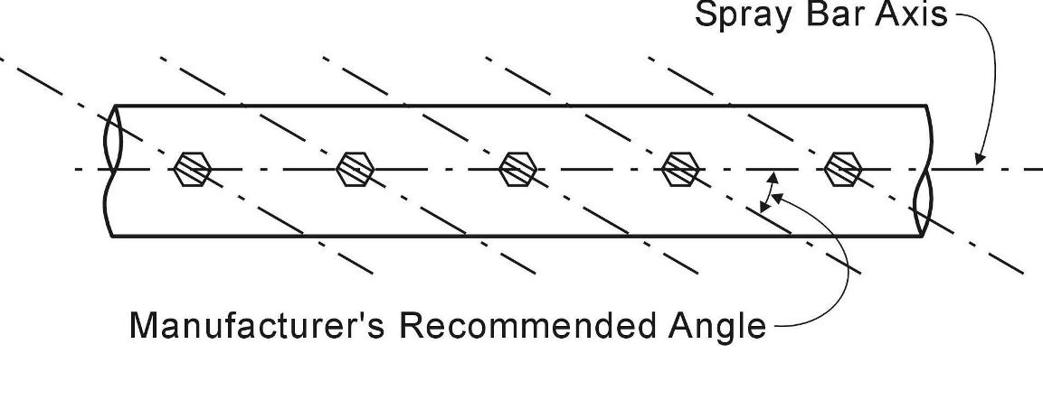
Figure 7-17. Nozzles on Spray Bar Set at Manufacturer’s Recommended Angle.
The proper spray pattern depends directly on the exactness of the nozzle angles. If not set correctly, the fan pattern can be distorted as shown in Figure 7‑18.
Figure 7-18. Effect of Incorrect Nozzle Angle.
Fan Width.
In addition to the nozzle angle, the height of the spray bar is critical to obtaining a correct spray pattern. The height of the bar above the surface of the roadway determines how wide the fan spreads. Triple lap coverage as shown in Figure 7‑19 is desirable and is achieved at a spray bar height of 12 inches.
Figure 7-19. Various Asphalt Spray Patterns.
Standard truck springs will compress under a heavy load, and flex back to an arch when the load is removed. If an asphalt distributor had standard springs, the spray bar would be one height when the tank is full. As the asphalt is sprayed and the tank empties, the spray bar would rise with the decreased weight on the springs. Consequently, the beginning of the shot would have triple lap coverage, but the lap would increase as the spray bar height increases. This would cause streaking.
To avoid this inconsistency, most distributors are equipped to either prevent the springs from compressing under a load or to prevent them from arching back with a near-empty tank. Many are stabilized with compressed air. The important point is that the spray bar should remain at a constant height whether the tank is full or empty.
To check the fan width, the operator should back onto a flat area and place one or two layers of brown paper under the spray bar. Have the operator turn the spray on momentarily. Make certain he turns it off as quickly as possible. This will not give an exact representation of the fan widths, but it will quickly reveal any problems with the spray pattern. If this is not conclusive, the operator may spray a short test strip (20 to 30 feet). This will usually reveal any nozzle problems.
Nozzle Output.
The amount of asphalt being sprayed out of each nozzle will vary. Nozzle output should be tested in accordance with TxDOT Test Method Tex 922-K, Part III (bucket test) to ensure each nozzle is spraying within the correct tolerance.Buckets for the bucket test must be shaped so they will fit under the nozzles side-by-side. A 4-inch diameter by 8-inch height concrete cylinder mold as shown in Figure 7‑20 is commonly used for the bucket test.
Figure 7-20. Concrete Cylinder Mold Typically Used for Spray Bar Calibration.
If asphalt is used for the test, it should be heated to the temperature at which it will be applied. Water may also be used for this test. Before the test begins, the spray bar should be turned on for a short period of time to make certain none of the nozzles are clogged. The distributor should be moved off the test area to blow out the nozzles.
If all nozzles are working, the test can proceed. If any nozzles are clogged, they should be removed and cleaned or taken out of service.
A container should be placed under each nozzle to catch all the flow from that nozzle as shown in Figure 7‑21. Set the pump pressure or speed to match the application rate for the seal coat work. When the containers are all in position, turn the sprayer on briefly to fill the containers to about 3/4 full.
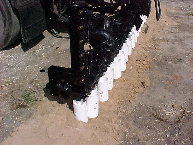
Figure 7-21. Calibration of Asphalt Distributor Spray Bar.
Item 316,
Surface Treatments
, requires that there be no more than a 10 percent variation in the weight of the contents between each bucket. If water is used for this test, all water must be removed from the distributor tank after calibrating the spray bar. Adding hot asphalt will cause water in the tank to be converted to steam resulting in an explosion, which may result in serious injury. At the least the asphalt tank is likely to overflow via the manhole, possibly endangering those nearby.Transverse Variation.
Some seal coat work may require the application of more asphalt binder outside the wheel paths to prevent aggregate shelling. The rate variation can be achieved by using different nozzle sizes outside the wheel path versus in the wheel path.